Table of Contents
Advertisement
Quick Links
Advertisement
Table of Contents

Subscribe to Our Youtube Channel
Related Manuals for Vision Engineering KESTREL


Summary of Contents for Vision Engineering KESTREL
- Page 1 2 Axis Non-contact Measuring System Assembly, Usage & Maintenance Guidelines...
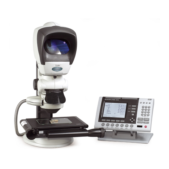
- Page 3 Vision's patented optical viewing system presents the operator with a magnified, crisp, bright and undistorted view of the component to be measured. Below the Kestrel's optics, the accurate XY stage is moved, allowing for features to be positioned on the central crosshair, shown in the viewing head.
-
Page 4: Table Of Contents
Attaching Spot Illuminator Photographic Attachments Microprocessor Assembly System Cable Connection Operation & Setup Main System Controls Stage Glass Levelling EPI/Lens Controls Graticule Adjustment Spot Adjustment How to use your Kestrel Measuring System Objective Lens Illumination Options Taking a Measurement Good Working Practices... - Page 5 Getting the most from your Kestrel Routine Maintenance Consumable & Replacement Parts Environmental Considerations Routine Maintenance General Maintenance Points Sub-Stage Lamp Changing Illuminator Lamp Changing Product Family Family Tree Accessories & Additional Features Ringlight Episcopic Illumination Camera Arm Lens Options...
-
Page 7: Packing Contents
Packing Contents Please look for the following parts in each pack. Each pack has a check list on the outside of its contents. Packing Contents HEAD PACK Column & Stand STAGE & STAND PACK Stage Stage Glass MICROPROCESSOR PACK www.visioneng.com/support Page 1... -
Page 8: Focus Pack Optional Items
Packing Contents Focus Assembly FOCUS PACK (standard) OPTIONAL ITEMS Ringlight Spotlight EPI Lamp Objective Lenses Photographic Adaptor FOOTSWITCH ACCESSORIES PACKS Illuminator NOTE: The Illuminator & Power Supply pack is only required if an EPI is supplied. Power Supply Page 2 www.visioneng.com/support... -
Page 9: Assembly
Assembly Assembly STAGE ASSEMBLY Remove the red locking plate at the rear of the stage. Check the adjustable pad on the stage is retracted up into the stage bottom plate. The adjustable pad is controlled by the screw in the rear left hole in the aperture under the stage glass. -
Page 10: Fibre-Optic Cable Connection
Assembly FIBRE-OPTIC Locking Ferrule CABLE Collar CONNECTION Grub Fibre-Optic Screw Cable Indent 1. Unscrew the Locking Collar. 2. Remove the Locking Collar and Ferrule. 3. Insert the Fibre-Optic NOTE: cable through the Only for EPI option Collar and Ferrule. Align the Grub Screw with the indent on the RINGLIGHT CABLE cable and tighten the... -
Page 11: Focus Assembly Attachment
Assembly FOCUS ASSEMBLY ATTACHMENT Ensure the Coarse Column Travel Stop is at its lowest position and the Anti-Glare Shield is raised. Focus Column Assembly Connector Remove the Column Cap. Slide the assembly on to the column just enough to Coarse allow the column Travel Stop connector to be... -
Page 12: Epi Attachment
Assembly EPI ATTACHMENT Focus Assembly Securing Screw Episcopic Adapter Adapter Securing Screws (x 3) Episcopic RINGLIGHT & Illuminator Illuminator Securing SPOTLIGHT Screw ATTACHMENT Lens Holder Lens (WITH EPI) Focus Assembly Securing Screw Episcopic Adapter Adapter Securing Screws Episcopic (x 3) Illuminator Illuminator Securing Screw... -
Page 13: Objective Lens
Assembly OBJECTIVE LENS Objective Lens 1 Turn ATTACHING LED RINGLIGHT Place the ringlight into position and tighten Ringlight the securing screws. Attach the cable cable to the control box (see page 4). Securing Screws ATTACHING SPOT ILLUMINATOR Place the Spot Illuminator into position and tighten the securing screws. -
Page 14: Photographic Attachments
Assembly PHOTOGRAPHIC ATTACHMENTS Centring Screws Remove the Head. Place the Photographic Attachment Assembly into position and tighten the securing screw. Replace the head Head on to the assembly Focus Connector and tighten the Adjustment Head Securing Screw. Camera Attach the Interface appropriate Camera interface to the... -
Page 15: System Cable Connection
Assembly SYSTEM CABLE CONNECTION Mains On/Off NOTE: Switch Ensure the Voltage Selector is turned to the correct setting. For Japan and some Far Fuse Eastern markets the voltage X Axis Y Axis selector is marked 100 - 110V. Connector Connector Mains Input Connect Mains... -
Page 16: Operation & Setup
Operation & Setup MAIN SYSTEM CONTROLS & Switch the Kestrel On and Height check the red LED at the Adjustment centre of the Vision logo on Control the front of the Head is illuminated. Focus Adjust the Height Control Adjustment Control until you... -
Page 17: Graticule Adjustment
Operation & Setup GRATICULE NOTE: ADJUSTMENT The crosshair graticules are factory set and should not need routine adjustment. Depress the securing clip at the base of the front cover and lift the cover off. Retaining Knobs Securing Clip NOTE: The left-hand graticule is presented to the right-hand eye. - Page 18 Operation & Setup Head and LED illuminator control box Icons The icons on the front panel of the control box symbolise the following: On/Off switch Power on indicator Illuminator intensity control Ringlight connection point Dimmer On/Off Control Refer to manual Switch Temperature Protection HEAD Power for viewing unit (boom mount only)
-
Page 19: How To Use Your Kestrel Measuring System
How to use your Kestrel Measuring System To achieve the optimum results from your Kestrel Measuring System the illumination and optics need to be adjusted to provide the best possible image to the operator. Certain lighting options are better for some applications than others. -
Page 20: Taking A Measurement
How to use your Kestrel Measuring System Substage • Understage il lu mi na tion used only for the ac cu rate mea sure ment of through holes, pro files and edge fea tures for example. • Ad just in ten sity by ro tat ing thumbwheel on Kes trel base. -
Page 21: Getting The Most From Your Kestrel
Getting the most from your Kestrel To achieve the very best from your Kestrel non-contact measuring system, you should carry out regular, routine maintenance as well as undertaking a schedule of servicing and calibration (see service & calibration record page) Routine Maintenance (see pages 16, 17) •... -
Page 22: Routine Maintenance
Routine Maintenance Clean the viewing screen periodically with optical cloth. GENERAL MAINTENANCE Maintenanc POINTS If, after cleaning the viewing lens, the picture quality is below standard, Retaining Knobs remove and clean the graticules. If the graticules require adjustment after they have been cleaned, see page 11. -
Page 23: Sub-Stage Lamp Changing
Routine Maintenance ILLUMINATOR LAMP CHANGING NOTE: ENSURE THE ILLUMINATOR IS NOT HOT. Press down the bulb/fan assembly release button (see 1 above). 150W/21V Halogen Lamp Lift out the bulb/fan assembly (200 hour) (see 2 above). Disconnect the lamp as shown in 3 above. -
Page 24: Product Family
Product Family FAMILY TREE Product Family Page 18 www.visioneng.com/support... -
Page 25: Accessories & Additional Features
Camera Arm The camera arm is fitted between the optical head and the body of the Kestrel instrument. Video or still image can be captured using digital or CCTV video cameras with a ‘C’ mount threaded adaptor. Lens Options In addition to the standard x2 objective lens, x1 and x5 options are available. -
Page 26: Other Solutions From Vision Engineering
Other Solutions from Vision Engineering Other Solutions from Vision Engineering Vision Engineering manufactures a wide range of stereo inspection and non-contact measuring systems. Here is a summary of the products utilising Vision’s technology that are available to you. Stereo Inspection Systems... -
Page 27: Non-Contact Measuring Systems
Other Solutions from Vision Engineering Non-Contact Measuring Systems Product Picture Features Description • 150mm x 100mm stage 2-axis video measuring system with touch • X10 – X50 mag op tions screen video processor. Powerful yet Merlin • QC-300 Mi cro pro ces sor simple to use, ideal for a wide range of •... -
Page 29: Service & Calibration Record
Service & Calibration Record Service & Calibration Record Kestrel Serial Number ________________ Stage Serial Number ________________ Date of Date of Next Service Type Comments Company Signature Service Service www.visioneng.com/support Page 23... -
Page 31: Warranty
If during the warranty period the product is found to be defective, it will be repaired or replaced at facilities of Vision Engineering or elsewhere, all at the option of Vision Engineering. Shipment costs for warranty repairs, to and from Vision Engineering facilities will not, normally, be borne by Vision Engineering. - Page 32 Addresses For more information... Vision Engineering has a network of offices and technical distributors around the world. For more information, please contact your Vision Engineering branch, local authorised distributor, or visit our website. Vision Engineering Ltd. Vision Engineering Inc. Vision Engineering Ltd.
Need help?
Do you have a question about the KESTREL and is the answer not in the manual?
Questions and answers