Table of Contents
Advertisement
Quick Links
Advertisement
Table of Contents

Related Manuals for Vision Engineering OPTA


Summary of Contents for Vision Engineering OPTA
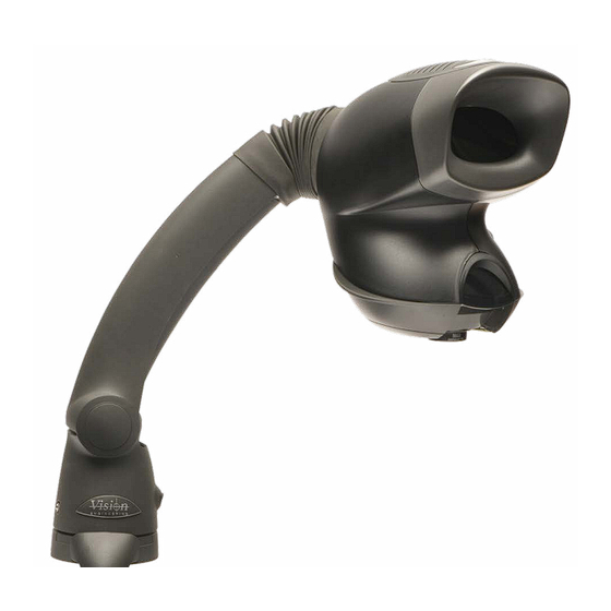
- Page 1 OPTA is the high performance stereo microscope designed to enhance operator performance in a wide USER GUIDE range of magnification tasks. It offers exceptional value, ensuring efficiency and effectiveness without compromising on excellence. www.visioneng.com...
- Page 2 INTRODUCTION GENERAL Safety Servicing Cleaning Symbols HEALTH & SAFETY Electrical Safety Illumination Environmental Considerations Operator Wellbeing Compliance Statements OPTA HEAD Unpacking Controls Fitting Lenses UNIVERSAL ARM Unpacking Assembly TRACK / CRESCENT STAND Unpacking Assembly OPTA HEAD Mounting to a Stand...
- Page 3 Vision Engineering Ltd. be liable for direct or indirect loss or damage of any kind, including loss of profit, revenue, goodwill or anticipated savings. All such warranties are hereby excluded to the fullest extent permitted by law.
- Page 4 OPTA is an easy to use, ergonomic, low magnification stereo microscope to maximise your productivity. In order to fully benefit from the significant ergonomic advantages afforded by your OPTA system, it is important to properly set-up and optimise your working environment.
- Page 5 • All operators have read, understood and observe the user manual, in particular the safety regulations. SERVICING Repairs may only be carried out by Vision Engineering-trained service personnel. Only original Vision Engineering spare parts may be used. CLEANING • Disconnect your system from the electrical source before cleaning.
-
Page 6: Health And Safety
Vision Engineering. • Electrical input to the OPTA head - 9V, 3A and Univeral Stand - 5V, 3Amp. • Power Supply Voltage (via plug top power supply) - 100-240V ~50/60Hz, 1.0A Max. -
Page 7: Compliance Statements
For more information visit: www.visioneng.com/ergonomics. COMPLIANCE STATEMENTS Vision Engineering and its products conforms to the requirements of the EC Directives on Waste Electrical and Electronic Equipment (WEEE) and Restriction of Hazardous Substances (RoHS). - Page 8 USER GUIDE UNPACKING OPTA Head Objective Lens (4x or 6x,) as ordered CONTENTS...
- Page 9 USER GUIDE CONTROLS Mounting Point IPD (interpupillary distance) Adjustment Power Input Lens Interface PREVIOUS CONTENTS...
- Page 10 USER GUIDE FITTING LENSES Lock Unlock REMOVE PROTECTOR CAP ON BOTTOM OF UNIT (IF FITTED) AND RETAIN FOR FUTURE USE To fit the lens 1. Locate 3 tabs of the objective lens into the slots on base of the unit and push upwards. 2.
- Page 11 USER GUIDE UNPACKING UNIVERSAL ARM OPTA Universal Arm Universal Mount G-clamp Dust Cover Power Supply CONTENTS...
- Page 12 USER GUIDE ASSEMBLY UNIVERSAL ARM Work surface mounting with clamp ASSEMBLY 1. Secure the universal mount to the work surface using the G-clamp provided or by using appropriate screws located in the holes of the mount. Screws are not supplied. Work surface mounting with screws 2.
- Page 13 USER GUIDE UNPACKING TRACK / CRESCENT STAND Track Stand Crescent base or Plain base (as ordered) Screws Adaptor Bracket (depending on the stand model) Power Supply CONTENTS...
- Page 14 USER GUIDE ASSEMBLY TRACK / CRESCENT STAND ATTACHING COLUMN TO BASE 1. Screw base plate to column using 4 screws provided 2. Fit adaptor bracket to focus block using 3 screws provided 3. Mount the head onto the stand (see mounting instructions) CONTENTS...
- Page 15 Replace retaining bolt passing it throuogh the locating mount MOUNT OPTA HEAD TO A STAND 1. Loosen the upper retaining bolt in the universal arm. 2. Remove the lower retaining bolt. 3. Carefully place the locating hook of the viewing head over the upper retaining bolt of the universal arm.
-
Page 16: Operation
USER GUIDE OPERATION OVERVIEW Turn on the power switch and place the subject beneath the viewing head. FOCUS The aim of the Universal Arm is that the height of the instrument is set to a comfortable viewing position and the subject is then lifted (normally by hand) into focus. Thus maintaining optimum ergonomics. - Page 17 USER GUIDE USER COMFORT ADJUSTING THE HEAD EYE SPACING Adjust the IPD (Interpupillary distance) knob on the side of the head to obtain a comfortable stereo view. Slowly turn the knob until the subject being viewed can be seen comfortably in both eyes. Adjusting the eye spacing is very important for viewing comfort and must be adjusted for each user.
-
Page 18: General Care
USER GUIDE GENERAL CARE CARING FOR YOUR OPTA CLEANING • When not in use, cover your with the dust cover provided. • Remove dust with a soft brush or cleaning cloth. • The lenses should be cleaned with a lens cleaning cloth. -
Page 19: Troubleshooting
USER GUIDE TROUBLESHOOTING NO POWER Check that jack plug is fully home in the socket. IMAGE LOOKS BLURRED • The lens could be dirty. The lens can be cleaned gently with a soft, dry cloth. A damp or course cloth can damage the coating and polished surface on the lens. •... -
Page 20: Service Record
USER GUIDE SERVICE RECORD SERVICE COMMENTS DATE OF SERVICE NEXT SERVICE DATE COMPANY SIGNATURE CONTENTS... -
Page 21: Warranty
If during the warranty period the product is found to be defective, it will be repaired or replaced at facilities of Vision Engineering or elsewhere, all at the option of Vision Engineering. However, Vision Engineering reserves the right to refund the purchase price if it is unable to provide replacement, and repair is not commercially practicable or cannot be timely made. -
Page 22: Specifications
USER GUIDE SPECIFICATIONS Objective Lenses Stand Options Crescent Stand Track Stand Universal Arm Objective Lenses Working Distance Field of View 96mm 27.5mm 73mm 19.2mm Maximum Dimensions Power Supply 9V DC external plug transformer (Universal Stand) 5V DC external plug transformer (Direct Head connection for Track Stands) A Workbench to top of head 533mm... - Page 23 USER GUIDE SERIAL NUMBER The images below indicate where you can find the serial number on each OPTA head. CONTENTS...
-
Page 24: System Options
SYSTEM OPTIONS MOS001 MOS003 MOS005 MOS002 MOS004 MOS006 Part Numbers MOS001 OPTA + X4 obj crescent base track stand kit MOS002 OPTA + X6 obj crescent base track stand kit MOS003 OPTA + X4 obj plain base track stand kit MOS004... - Page 25 Disclaimer - Vision Engineering Ltd. has a policy of continuous development and reserves the right to change or update, without notice, the design, materials or specification of any products, the information contained within this user guide and to discontinue production or distribution of any of the products described.
Need help?
Do you have a question about the OPTA and is the answer not in the manual?
Questions and answers