Table of Contents
Advertisement
Quick Links
Advertisement
Table of Contents

Subscribe to Our Youtube Channel
Related Manuals for Vision Engineering VE Cam


Summary of Contents for Vision Engineering VE Cam
- Page 1 Contents list Navigation instructions User guide VE Cam FM 557119...
- Page 2 NAVIGATION INSTRUCTIONS Contents The symbols in the left-hand margin of each page of the manual will enable you to carry out the following functions: Start page The buttons in text below do not function. They are for illustrative purposes only. Contents Click on this button to display the Contents page. Back one page. Forward one page.
- Page 3 SERIAL NUMBER Contents Unit serial number Start page Unit type Serial number VE Cam Stand Exit...
-
Page 4: Preface
Woking, Surrey GU23 7ER, UK All Rights Reserved. or implied, statutory or otherwise; without limiting the foregoing, the warranties Copyright in this document is owned by Vision Engineering Ltd. Any person is of satisfactory quality, fitness for a particular purpose or non-infringement are hereby authorised to view, copy, print and distribute this document subject to expressly excluded and under no circumstances will Vision Engineering Ltd. -
Page 5: General
Servicing Vision Engineering. Illumination safety Repairs may only be carried out by Vision Engineering-trained service Do not look directly at the illuminated LED’s. This may cause damage to personnel. Only original Vision Engineering spare parts may be used. the eyesight. -
Page 6: Operator Wellbeing
Contents The advanced ergonomic design and construction of Vision Engineering Vision Engineering and its products conforms to the requirements of the EC products are intended to deliver superior ergonomic performance, reducing Directives on Waste Electrical and Electronic Equipment (WEEE) and Restriction of Start page the exertion of the user to a minimum. -
Page 7: Table Of Contents
Contents Contents SERIAL NUMBER ASSEMBLY Start page Unit serial number Attaching VE Cam to the stand Connections PREFACE OPERATION Copyright Physical controls Disclaimer Interfaces General Safety Software controls Servicing Menu information bar Image manipulation Symbols used Software functions Warning! TECHNICAL DATA Important information Technical data Health &... -
Page 8: Introduction
Engineering Ltd. prides itself in designing and manufacturing products that make a real difference to your work. VE Cam 50 and 80 are the next additions to a line of ground breaking products. They offer a wide field of view, small footprint, and ease-of use (with a number of user set presets) to maximise your productivity. -
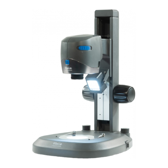
Page 9: Unpacking
UNPACKING Contents Unpacking the VE Cam Unpacking the stand Start page VE Cam Bench stand Mouse (not shown) Allen key Power supply (not shown) SX Microscope bracket HDMI cable (not shown) (not used) USB stick (not shown) Power cable Round inserts For substage... - Page 10 Connect either a touch screen or monitor to the HDMI socket Ensure that the spigot is fully inserted, with the VE Cam objective lens Use the rear USB ports to connect a mouse, optional keyboard, or touch pointing down, tighten the grub screw until the head is secure.
- Page 11 Turn the VE Cam on by pressing the On/Off button on the front of the head. When the VE Cam is turned on, a splash screen will be displayed while the unit boots up. A screen as below will then be displayed.
- Page 12 Two finger pinch zoom is supported via a touch screen. Once zoomed, the live image can be panned by sliding a finger on the screen. Vision Keypad Zoom functionality of the Vision Engineering Keypad is supported. USB Keyboard The following keys produce the following: ‘+’ + ‘CTRL’...
- Page 13 Contents Camera settings Lighting control To adjust the illumination level, click on the icon shown above and the lighting Click on the icon shown above to display the options. slider will be displayed. Start page When any function below has been selected and viewed or altered, return to Click on the slider and use it to adjust the ringlight’s illumination to the required level.
- Page 14 The first 3 hotkeys (P1 to P3) are also available on P1 to P3 of the Click to select the required crosshair colour. Vision Engineering keypad. Device settings When activated these controls will appear on the right hand side of the screen.
- Page 15 Import Settings - imports a settings file from a USB memory stick Down left Export Settings - Exports the current settings of the VE Cam to a file on a memory stick so that they can be ported to another VE Cam or recalled at a later time.
- Page 16 Function VE Cam50 VE Cam80 TECHNICAL DATA Contents Technical data Maximum subject height when mounted to a stand S240 - Bench Stand with Illumination 75mm 90mm Start page Optical data S206 - Boom Stand 87mm 102mm Function VE Cam50 VE Cam80 S241 - Double Arm Boom Stand 230mm 245mm Filed Of View S242 - Double Arm Boom Stand with Base 375mm 390mm Minimum Magnification...
- Page 17 Function VE Cam50 VE Cam80 Contents Menu languages English System weight German Start page VE Cam System Weight French Spanish Head weight VE Cam50 = 520g VE Cam80 = 504g Italian Stand weight (S240) 3.72kg Brazilian/Portuguese Chinese Total system VE Cam50 =4.24kg VE Cam80 = 4.22kg Japanese Russian All weights are net.
- Page 18 Check that power button is red when power is applied. Unit can not be controlled. Check that controller is connected into a USB socket on the VE Cam Image looks blurred Adjust focus using the fine adjustment of turning the objective lens The lens could be dirty.
- Page 19 SERVICING Contents Service record Start page Service Comments Date of service Date of next service Company Signature All product specifications and data are subject to change without notice Exit SERVICE RECORD...
- Page 20 This product is warranted to be free from defects in material and workmanship for a period of one year from the date of invoice to the original purchaser. If during the warranty period the product is found to be defective, it will be repaired or replaced at facilities of Vision Engineering or elsewhere, all at the option of Vision Engineering.
- Page 21 Visit our multi-lingual website: www.visioneng.com Disclaimer – Vision Engineering Ltd. has a policy of continuous development and reserves the right to change or update, without notice, the design, materials or specification of any products, the information contained within this brochure/datasheet and to discontinue production or distribution of any of the...
Need help?
Do you have a question about the VE Cam and is the answer not in the manual?
Questions and answers