
Related Manuals for GreenWorks CU800


Summary of Contents for GreenWorks CU800
- Page 1 CU800 Service Manual Utility Vehicle 7402902 / 7402802 Model No. CU800 Service Manual WARNING: Read all safety rules and instructions carefully before operating this tool. Rev 1.0...
- Page 2 CU800 Service Manual CU800 Service Manual The manual is edited by Greenworks Group, and is supplied to dealers and technicians as document of technique. Mainly, the handbook gives methods to check, maintain and repair electric vehicles (EV), and supplies some relevant technique and performance data.
-
Page 3: Table Of Contents
CONTENT CHAPTER 1 GENERAL INFORMATION……………………………………………………1 CAUTIONS AND NOTES…………………………………………………1 1.1 WATNINGS 1.2 DESCRIPTION………………………………………………………………………………2 1.3 IDENTIFICATION CODE………………………………………………………………… 3 1.4 SAFETY …………………………………………………………………………………… 4 1.4.1 Operator Safety………………………………………………………………………… 4 1.4.2 Battery Safety…………………………………………………………………………… 7 1.4.3 Cleaning Parts…………….….………………………………………………………… 8 1.4.4 Warning Labels…………………….….………………………………………………… 8 1.5 SERIAL NUMBERS………………………………………………………………………… 8 1.6 FASTENERS………………………………………………………………………………... - Page 4 1.8.9 Pliers…………………………………………………………………………………… 17 1.8.10 Snap Ring Pliers……………………………………………………………………… 18 1.8.11 Hammers ……………………………………………………………………………… 19 1.9 PRECISION MEASURING TOOLS …………………………………………………… 19 1.9.1 Dial Indicator ………………………………………………………………………… 19 1.9.2 Insulation Tester………………………………………………………………………… 19 1.9.3 Multimeter…………………………………………………………………………… 20 1.9.4 Ohmmeter (analog) Calibration……………………………………………………… 20 1.9.5 Clip-on Ammeter…………………….……………………………………………………21 1.10 ELECTRICAL SYSTEM FUNDAMENTALS………………………………………… 22 1.10.1 Voltage …………………………………………………………………………………...
- Page 5 1.15 THE STORAGE AND CLEANING ……….……………...……………..….……….… 38 1.15.1 Cleaning………………………………………………………………………………… 38 1.15.2 Storage……………......…………………………………………………… 39 1.16 IMPORTANT ELECTRICAL COMPONENTS……………………………………… 40 1.16.1 Motor and Controller ………………………………………………………………… 40 1.16.2 Battery………………………..…………...……………………………...………40 1.16.3 Battery Charger………………………………………………………………………… 40 1.16.4 Charging Batteries………………...………………………………………… 41 1.16.5 Charging Quantity Indicator………………………………………………………….42 1.16.5.1 Charging Heating Strategy………………………...………………………………43 1.16.5.2 Discharge Heating Strategy…………………………………………..…………43 1.16.6 Plug and Receptacle…………………………………………………...………………43 1.17 STORAGE………………………......……………………………………...
- Page 6 1.20.2 Brake Drag…………………………………………………………………………… 53 1.20.3 Hard Brake Lever or Pedal Operation…………….………………………………… 53 1.20.4 Brake Grabs…………………………………………………………………………… 54 1.20.5 Brake Squeal or Chatter …………………………………………………………… 54 1.20.6 Leaking Brake Caliper …………………...……….………………………………… 54 1.20.7 Leaking Master Cylinder………………………….………………………………… 54 CHAPTER 2 SPECIFICATIONS………………………………………………………………55 2.1 CONVERSION TABLE……………………………………..……………….… 55 2.2 DEFINITION OF UNIT ……………………………………………………………...
- Page 7 3.3 ELECTRICAL……………………………………………………………………………….79 3.3.1 Checking and charging the battery…………………………………………………… 79 3.3.2 Checking the fuses …………………………………………………………………… 84 3.3.3 Adjusting the headlight beam………………………………………………………… 86 3.3.4 Changing the headlight bulb……………………………………………………..…86 3.3.5 Changing the tail/brake light bulb …………………………………………………… 87 CHAPTER 4 MOTOR AND DRIVING SYSTEM…………………………………………….88 4.1 INSPECTION AND REPAIRING OF MOTOR…………………………………..……88 4.1.1 Motor Mechanical Structure…………...……………………………….………………...
- Page 8 CHAPTER 7 ELECTRICAL SYSTEM MALFUNCTION INSPECTION…………………199 7.1 ELECTRICAL COMPONENTS…………………………………………...………….… 202 7.2 CHARGING SYSTEM………………………………………………………………… 206 7.3 LIGHTING SYSTEM…………………………………………………………………… 207 7.4 SIGNALING SYSTEM………………………………………………………………… 210 7.5 2WD/4WD SELECTING SYSTEM…………………………………………………… 216 CHAPTER 8 TROUBLESHOOTING………………………………….…….……………...219 8.1 BODY PARTS AND PROTECTION PARTS…………………...………………...…... 219 8.2 BRAKING SYSTEM ………......………………………………………... 219 8.3 ELECTRICAL SYSTEM ……………………………..........…...
-
Page 9: Chapter 1 General Information
GENERAL INFORMATION CU800 Service Manual GENERAL INFORMATION CHAPTER 1 The text provides complete information on maintenance, tune-up repair and overhaul. Hundreds of photographs and illustrations created during the complete disassembly of four wheel electric vehicles (EV) guide the reader through every job. All procedures are in step-by-step format and designed for the reader who may be working on the EV for the first time. -
Page 10: Description
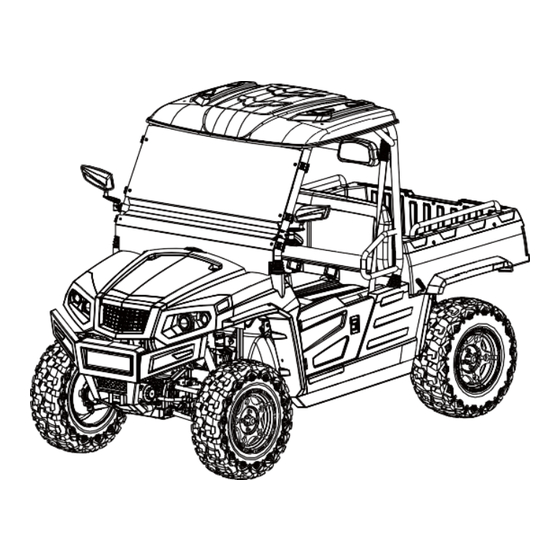
GENERAL INFORMATION CU800 Service Manual 1.2 DESCRIPTION 1. Headlight Assy 2. Front Shock Absorber Assembly Unit Q (Gasbag Shock Absorber) 3. Disc brake cup 4. Steering Wheel Comp 5. Driver Seat 6. Driver Safety Belt 7. Rear Cargo 8. Rear Shock Absorber Assembly Unit Q(Gasbag Shock Absorber) 9. -
Page 11: Identification Code
GENERAL INFORMATION CU800 Service Manual 1.3 IDENTIFICATION CODE Electric motor No. Electric motor NO. is behind the electric motor Frame No. Frame No. is carved on the right side of rear frame... -
Page 12: Safety
Never turn at excessive speeds. Always have this vehicle checked by Greenworks dealer if it has been involved in an accident. Never operate this vehicle on hills too steep for the vehicle or for your abilities. Practice on smaller hills before attempting larger hills. - Page 13 Always use the proper size and type of tires specified in this manual. Always maintain proper tire pressure as specified on safety labels. Never modify this vehicle through improper installation or use of non-Greenworks-approved accessories. Never exceed the stated load capacity for this vehicle. Cargo should be properly distributed and securely attached.
- Page 14 GENERAL INFORMATION CU800 Service Manual performing maintenance, service, or accessory installation. ⚫ Wear safety glasses or approved eye protection when servicing the vehicle or battery charger. Wear a full face shield and rubber gloves when working on or near battery.
-
Page 15: Battery Safety
GENERAL INFORMATION CU800 Service Manual 1.4.2 Battery Safety WARNING: ⚫ High Voltage Danger: High voltage electrical hazards may cause serious injuries and be life-threatening. The user cannot dismantle any parts or repair casually. WARNING: ⚫ Chemical Danger: The lithium iron phosphate battery may contain inflammable gas and acidic electrolyte. -
Page 16: Cleaning Parts
GENERAL INFORMATION CU800 Service Manual 1.4.3 Cleaning Parts Cleaning parts is one of the more tedious and difficult service jobs performed in the home garage. Many types of chemical cleaners and solvents are available for shop use. Most are poisonous and extremely flammable. -
Page 17: Torque Specifications
GENERAL INFORMATION CU800 Service Manual WARNING: ⚫ High Voltage Danger: Do not install fasteners with a strength classification lower than what was originally installed by the manufacturer, doing so may cause equipment failure and or damage. 1.6.1 Torque Specifications The material used in the manufacturing of the EV may be subjected to uneven stresses if the fasteners of the various subassemblies are not installed and tightened correctly. -
Page 18: Snap Rings And E-Clips
GENERAL INFORMATION CU800 Service Manual 1.6.5 Snap Rings and E-clips Snap rings (Figure 1) are circular-shaped metal retaining clips. They secure parts in place on parts such as shafts. External type snap rings are used to retain items on shafts. Internal type snap rings secure parts within housing bores. -
Page 19: Shop Sipplies
GENERAL INFORMATION CU800 Service Manual 1.7 SHOP SIPPLIES 1.7.1 Lubricants and Fluids Periodic lubrication help ensure a long service life for any type of equipment. Using the correct type of lubricant is as important as performing the lubrication service. Although in an emergency the wrong type is better than not using one.The following section describes the types of lubricants most... -
Page 20: Gasket Sealant
GENERAL INFORMATION CU800 Service Manual 1.7.5 Gasket Sealant Sealant is used in combination with a gasket or seal. In other applications, such as between crankcase halves, only a sealant is used. Follow the manufacturer’s recommendation when using a sealant. Use extreme care when choosing a sealant different sealant based on its resistance to heat, various fluids and its sealing capabilities. -
Page 21: Screwdrivers
GENERAL INFORMATION CU800 Service Manual 1.8.1 Screwdrivers Screwdrivers of various lengths and types are mandatory for the simplest tool kit. The two basic types are the slotted tip (flat blade) and the Phillips tip. These are available in sets that often include an assortment of tip size and shaft lengths. -
Page 22: Adjustable Wrenches
GENERAL INFORMATION CU800 Service Manual fastener at only two points and is subject to slipping if under heavy force, or if the tool or fastener is worn. A box-end wrench is preferred in most instances, especially when braking loose and applying the final tightness to a fastener. -
Page 23: Impact Drivers
GENERAL INFORMATION CU800 Service Manual Use hand sockets with hand-driven attachments. WARNING Do not use hand sockets with air or impact tools because they may shatter and cause injury. Always wear eye protection when using impact or air tools. Various handles are available for sockets. Use the speed handle for fast operation. -
Page 24: Allen Wrenches
GENERAL INFORMATION CU800 Service Manual 1.8.6 Allen Wrenches Use Allen or setscrew wrenches (Figure 11) on fasteners with hexagonal recesses in the fastener head. These wrenches are available in L- shaped bar. Socket and T-handle types. A metric set is required when working on most motorcycles. - Page 25 GENERAL INFORMATION CU800 Service Manual not equal the actual torque applied to the fastener. It is necessary to recalibrate the torque setting on the wrench to compensate for the change of lever length. When using a torque adapter at a right angle to the drive head, calibration is not required, because the effective length has not changed.
-
Page 26: Pliers
GENERAL INFORMATION CU800 Service Manual 1.8.9 Pliers Pliers come in a wide range of types and sizes. Pliers are useful for holding, cutting, bending, and crimping. Do not use them to turn fasteners. Figure 15 and Figure 16 show several types of useful pliers. -
Page 27: Hammers
GENERAL INFORMATION CU800 Service Manual 1.8.11 Hammers Various types of hammers are available to fit a number of applications. Use a ball-peen hammer to strike another tool, such as a punch or chisel. Use soft-faced hammers when a metal object must be struck without damaging it. -
Page 28: Multimeter
GENERAL INFORMATION CU800 Service Manual An Insulation tester (Figure 34) is an essential tool for electrical system diagnosis. Insulation tester is suitable for insulation test in maintenance, repair, test and verification of various electrical equipment. Insulation tester is used to test the insulation... -
Page 29: Clip-On Ammeter
GENERAL INFORMATION CU800 Service Manual 4. If necessary, rotate the meter ohms adjust knob until the needle and 0 mark align. 1.9.5 Clip-on ammeter Clip-on ammeter (Figure 35) is the basic tool for electrical system diagnosis which is used to measure the current of charging system and other electrical components work current. -
Page 30: Electrical System Fundamentals
GENERAL INFORMATION CU800 Service Manual 1.10 ELECTRICAL SYSTEM FUNDAMENTALS A thorough study of the many types of electrical systems used in today’s motorcycles is beyond the scope of this manual. However, a basic understanding of electrical basics is necessary to perform simple diagnostic tests. -
Page 31: Basic Service Methods
GENERAL INFORMATION CU800 Service Manual 1.11 BASIC SERVICE METHODS Most of the procedures in this manual are straightforward and can be performed by anyone reasonably competent with tools. However, consider personal capabilities carefully before attempting any operation involving major disassembly. -
Page 32: Removing Frozen Fasteners
GENERAL INFORMATION CU800 Service Manual tools are required, they are described at the beginning of the procedure. 15. Make diagrams of similar-appearing parts. For instance, crankcase bolts are often not the same lengths. Do not rely on memory alone. Carefully laid out parts can become disturbed, making it difficult to reassemble the comports correctly. -
Page 33: Repairing Damaged Threads
GENERAL INFORMATION CU800 Service Manual 1.11.3 Repairing Damaged Threads Occasionally, threads stripped through carelessness or impact damage. Often the threads can be repaired by running a tap (for internal threads on nuts) or die (for external threads on bolts) through the threads (Figure 39). -
Page 34: Removing Hoses
GENERAL INFORMATION CU800 Service Manual 1.11.5 Removing Hoses When removing stubborn hoses, do not exert excessive force on the hose or fitting. Remove the hose, do not exert excessive force on the hose or fitting. Remove the hose clamp and carefully insert a small screwdriver or pick tool between the fitting and hose. -
Page 35: Installation
GENERAL INFORMATION CU800 Service Manual a press: Always support the inner and outer bearing races with a suitable size wooden or aluminum spacer (Figure 44). If only the outer race is supported, pressure applied against the balls and/or the inner race will damage them. -
Page 36: Interference Fit
GENERAL INFORMATION CU800 Service Manual 3. When installing a bearing as described in Step 1, some type of driver is required. Never strike the bearing directly with a hammer or it will damage the bearing. When installing a bearing, use a piece of pipe or a driver with a diameter that matches the bearing inner race. -
Page 37: Seal Replacement
GENERAL INFORMATION CU800 Service Manual CAUTION Before heating the housing in this procedure, wash the housing thoroughly with detergent and water. Rinse and rewash the cases as required to remove all traces of oil and other chemical deposits. a. Heat the housing to approximately 100℃ (212° F) in an oven or on a hot plate. An easy way to check that it is the proper temperature is to place tiny drops of water on the housing;... -
Page 38: Basic Driving And Operating Methods
GENERAL INFORMATION CU800 Service Manual 1. Prying is generally the easiest and most effective method of removing a seal from the housing. Always place a rag underneath the pry tool to prevent damage to the housing. Note the seal’s installed depth or if it is installed flush. - Page 39 GENERAL INFORMATION CU800 Service Manual 3. Turn the key switch to "ON" position. Dashboard will be lit, indicating whether the battery is fully charged. 5. Turn the forward / reverse switch to the desired position. F: Forward Center position:Neutral R: Reverse (At this moment, the buzzer will make sound signal) ①...
-
Page 40: Operation Before Leaving The Ev
GENERAL INFORMATION CU800 Service Manual 8. Slowly press down the accelerator pedal, EV can increase speed, press the pedal to the end, you can achieve maximum speed. 9. Release the accelerator pedal and press down the brake pedal, you can make EV to stop moving. -
Page 41: Motor Braking Function
GENERAL INFORMATION CU800 Service Manual 5. Turn key OFF and remove key when not in use. 1.12.3 Motor Braking Function In operation, when press down the brake pedal, turn electric Motor brake on to limit the speed and recover energy to charge the battery. -
Page 42: Daily Safe Checking
GENERAL INFORMATION CU800 Service Manual 1.13 DAILY SAFE CHECKING Before driving, it is necessary to make a daily safe checking of the vehicle, so that you can found any possible problem and failure. If you find any failure, adjustment or maintenance must be carried out immediately; otherwise you may cause serious injury or property damage. -
Page 43: Performance Checking Items
GENERAL INFORMATION CU800 Service Manual Motor and Controller Connection Terminal Specification Chart Charger cord, plug, and socket: Visual check for cracks, looseness and abrasion of wire insulation. Hand check if cable plugs and sockets are loose. If the Error is found, please go to the dealer to conduct a comprehensive inspection on the charger. -
Page 44: Maintence And Adjustment Of The Ev
GENERAL INFORMATION CU800 Service Manual MAINTENCE AND ADJUSTMENT OF THE EV 1.14 To ensure trouble-free vehicle performance, it is very important to follow an established preventive maintenance program. Meanwhile, regular maintenance can greatly extend the service life of EV. Regular and consistent vehicle maintenance can prevent vehicle downtime and expensive repairing cost that could be resulted because of neglect. -
Page 45: Periodic Service Schedule
GENERAL INFORMATION CU800 Service Manual 1.14.1 Periodic Service Schedule REGULAR INTERVAL SERVICE Pre-Operation and Daily Safety Checklist Daily service by owner Performance Inspection Batteries Weekly service by Check the battery weekly, charge the battery in time owner Check the battery monthly, charge the battery in time... -
Page 46: Periodic Lubrication Schedules
GENERAL INFORMATION CU800 Service Manual 1.14.2 Periodic Lubrication Schedules PERIODIC LUBRICATION SCHEDULE REGULAR RECOMMENDED LUBRICATION LUBRICATION PARTS POINTS INTERVAL LUBRICANT Charger receptacle WD-40 Semiannual service Lubricate the brake system by trained After each maintenance lithium grease technician (every 50 and service manual... -
Page 47: Storage
GENERAL INFORMATION CU800 Service Manual 2. Manufacturer does not recommend using any pressure cleaning or steam cleaning methods on EVs for cleaning. Because this cleaning method will make electronic parts get wet, which can cause a short circuit, corrosion and electrical components malfunction. -
Page 48: Important Electrical Components
WARNING: • DANGER! HIGH VOLTAGE! • Only Greenworks Commercial dealer or authorized service center can disconnect the battery. • If the vehicle is stored for a long time, charge the vehicle to 50% battery capacity monthly. • Use insulated tools when working near batteries or electrical connections. Use extreme caution to avoid shorting of components or wiring. -
Page 49: Charging Batteries
GENERAL INFORMATION CU800 Service Manual ⚫ Connect the charger with AC power cord, and ensure voltage and frequency of 90~265V/45~65HZ. ⚫ An extension cord or electrical outlet must accept a three-prong plug. Improper receptacle can cause fire or personal injury. -
Page 50: Charging Quantity Indicator
GENERAL INFORMATION CU800 Service Manual ⚫ Do not pull on the DC cord Do not twist, rock or bend the plug. To disconnect the charger plug from AC power receptacle, grasp the plug by the handle and pull the plug straight out of the receptacle. -
Page 51: Charging Heating Strategy
GENERAL INFORMATION CU800 Service Manual 1.16.5.1 Charging heating strategy > 5 ℃, pure heating, request 3.5A heating. When T <25 ℃, When T > =5 degrees & T > =25 ℃, charge while heating, request 15A (where 3.5A is the heating current). When T pure charge, request 30A. -
Page 52: Storage
GENERAL INFORMATION CU800 Service Manual 1.17 STORAGE Several months of non-use can cause a general deterioration of the EV. This is especially true in areas of extreme temperature variations. This deterioration can be minimized with careful preparation for storage. A properly stored EV is much easier to return to service. -
Page 53: Troubleshooting
GENERAL INFORMATION CU800 Service Manual 1.18 TROUBLESHOOTING Diagnose electrical and mechanical problems by following an orderly procedure and remembering the basic operating requirements. → Define Symptoms ↓ → Which areas could exhibit these Determine symptoms ↓ → Test and The suspect areas analyze ↓... -
Page 54: Electrical Testing
GENERAL INFORMATION CU800 Service Manual 1.19 ELECTRICAL TESTING This section describes basic electrical testing and test equipment use. 1.19.1 Preliminary Checks and Precautions Refer to the color wiring diagrams at the end of the manual for component and connector identification; Use the wiring diagrams to determine how the circuit should work by tracing the current paths from the power source through the circuit components to ground. -
Page 55: Electrical Component Replacement
GENERAL INFORMATION CU800 Service Manual connector A change in meter readings indicates a poor connection. Fine and repair the problem or replace the part. Check for wires with cracked or broken insulation Heat – This is another common problem with connectors or plugs that have loose or poor connections. -
Page 56: Ammeter
GENERAL INFORMATION CU800 Service Manual 1.19.5 Ammeter An ammeter measures the flow of current (amps) in a circuit when connected in series in a circuit, the ammeter determines if current is flowing through the circuit and if that current flow is excessive because of a short in the circuit. -
Page 57: Insulation Tester
GENERAL INFORMATION CU800 Service Manual 1.19.8 Insulation Tester The insulation tester can be used to check whether the 76.8V system of the motor has leakage and series current, its own power source is able to output 50V to 1000V DC high voltage to detects the insulation resistance between the power supplies of the electrical parts. -
Page 58: Test Procedures
GENERAL INFORMATION CU800 Service Manual To isolate the problem. Connect the jumper between the battery and the lamp. If it comes on. The problem is between these two points. Next. Connect the jumper between the battery and the fuse side of the switch. -
Page 59: Continuity Test
GENERAL INFORMATION CU800 Service Manual Because resistance causes voltage to drop. A voltmeter is used to measure voltage drop when current is running through the circuit. If the circuit has no resistance. There is no voltage drop so the voltmeter indicates 0 volts. The greater the resistance in a circuit. The greater the voltage drop reading. -
Page 60: Testing For A Short With Test Light Or Voltmeter
GENERAL INFORMATION CU800 Service Manual wiring harness relating to the suspect circuit at various intervals. Start next to the fuse terminals and work away from the fuse terminal. Watch the self-powered test light or ohmmeter while progressing along the harness. -
Page 61: Brake Drag
GENERAL INFORMATION CU800 Service Manual 3. Leak in the brake system. 4. Contaminated brake fluid. 5. Plugged brake fluid passages. 6. Damaged brake lever or pedal assembly. 7. Worn or damaged brake pads. 8. Warped brake disc. 9. Contaminated brake pads and disc. -
Page 62: Brake Grabs
GENERAL INFORMATION CU800 Service Manual 6. Damaged front brake lever. 7. Damaged rear brake pedal. 8. Brake caliper not sliding correctly on slide pins. 9. Worn or damaged brake caliper seals. 1.20.4 Brake Grabs 1. Damaged brake pad pin bolt. Look for steps or cracks along the pad pin bolt surface. -
Page 63: Chapter 2 Specifications
SPECIFICATIONS CU800 Service Manual CHAPTER 2 SPECIFICATIONS 2.1 CONVERSION TABLE All the specified documents in this manual are taken SI and Metric as unit. With the following conversion table, metric unit could be converse into imperial unit. Sample: METRIC MULTIPLY IMPERIAL 0.03937... -
Page 64: Vehicle Specifications
SPECIFICATIONS CU800 Service Manual 2.3 VEHICLE SPECIFICATIONS Item Standard Dimensions: Overall length 3,000mm (118.1 in) Overall width 1,600mm(63 in) Overall height 2,050mm(80.7 in) Seat height 860mm(33.85 in) Wheelbase 1950mm(75.77 in) Minimum ground clearance 355mm(13.98 in) Minimum turning radius 3400mm (133.86 in) Basic weight: 795kg (1752.7 lbs) - Page 65 SPECIFICATIONS CU800 Service Manual Tire Type Tubeless 26×9-14 6PR Size Front Rear 26×11-14 6PR 15psi (103kPa) Pressure of front wheel 18psi (124kPa) Pressure of rear wheel Brake Front brake Type Hydraulic disc brake Operation Foot operation Rear brake Type Hydraulic disc brake...
-
Page 66: Chassis Specifications
SPECIFICATIONS CU800 Service Manual 2.4 CHASSIS SPECIFICATIONS Item Standard Limit Steering system Type Rack and pinion ---- Front suspension Shock absorber travel 160 mm (6.3 in) ---- Spring free length 294 mm (11.57 in) ---- Spring rate 19.04N/mm(1.94kg/mm) ---- Stroke 30-140 mm (1.18 ~ 5.51in) -
Page 67: System Electrical Specifications
SPECIFICATIONS CU800 Service Manual Item Standard Limit Front disc brake Type Dual ---- Disc outside diameter × thickness 200× 3.5 mm (7.87 × 0.14 in) ---- Pad thickness inner 6.0 mm (0.24 in) ---- Pad thickness outer 6.0 mm (0.24 in) - Page 68 SPECIFICATIONS CU800 Service Manual 2.6 76.8V SYSTEM ELECTRICAL SPECIFICATIONS Item Standard Limit Controller parameter3 ---- Working voltage 76.8 VDC Voltage range 67.2V-86.4VDC PWM frequency 10KHz Over-voltage protective voltage low-voltage protective voltage Pulling motor current limit 350A overheat protective temperature 95℃...
- Page 69 SPECIFICATIONS CU800 Service Manual Earthing protection. Power-off Protection. Item Standard Limit DC/DC Model TDC-IY-72-12 Rated input voltage 44-97V Peak current Rated Power 1000W Output voltage ≥94% Full load efficiency -40℃~+65℃ Working Temperature IP67 Protection class Input Over-voltage Protection, Input Protection function...
-
Page 70: Lubrication Points And Lubricant Types
SPECIFICATIONS CU800 Service Manual 2.7 LUBRICATION POINTS AND LUBRICANT TYPES Lubrication points Lubricant Lip of oil seal (full) Light lithium-base grease O-ring (full) Light lithium-base grease Steering shaft (upper end, lower end) Light lithium-base grease Ball connection of steering pushing rod... -
Page 71: Chapter 3 Maintence And Adjustment Of The Ev
MAINTENANCE AND ADJUSTMENT OF EV CU800 Service Manual CHAPTER 3 MAINTENANCE AND ADJUSTMENT OF THE EV NOTE: The correct maintenance and adjustment are necessary to ensure vehicle and normal driving The repair personnel should be familiar with the contents of this article. -
Page 72: Chassis
MAINTENANCE AND ADJUSTMENT OF EV CU800 Service Manual NOTE: ·Recommended brake fluid: DOT 3 ·Brake fluid replacement: ·When disassembling the master cylinder or caliper, replace the brake fluid. Normally check the brake fluid level and add fluid as required. ·On the inner parts of the master cylinder and caliper, replace the oil seals every two years. -
Page 73: Adjusting The Parking Brake
MAINTENANCE AND ADJUSTMENT OF EV CU800 Service Manual 3.2.2 Adjusting the Parking Brake 1. Shift the drive select lever into neutral gear. 2. Remove: ·lift the hood up Refer to “SEATS” in chapter5 3. Check: ·parking brake cable free play Out of specification Adjust. -
Page 74: Checking The Front Or Rear Brake Pads
MAINTENANCE AND ADJUSTMENT OF EV CU800 Service Manual otherwise, the rubber seals may deteriorate, causing leakage and poor brake performance. · Refill with the same type of brake fluid: mixing fluids may result in a harmful chemical reaction lead poor performance. -
Page 75: Bleeding The Hydraulic Brake System
MAINTENANCE AND ADJUSTMENT OF EV CU800 Service Manual 3.2.6 Bleeding the Hydraulic Brake System WARNING Bleed the brake system if: · The system has been disassembled. · A brake hose or brake pipe have been loosened or removed. · The brake fluid has been very low. -
Page 76: Checking The Final Gear Oil Level
MAINTENANCE AND ADJUSTMENT OF EV CU800 Service Manual 3.2.7 Checking the Final Gear Oil Level 1. Place the vehicle on a level surface. 2. Remove: ·oil filler plug ① 3. Check: ·oil level Oil level should be up to the brim of the hole. -
Page 77: Checking The Differential Gear Oil
MAINTENANCE AND ADJUSTMENT OF EV CU800 Service Manual 5. Install: ·oil filler plug and Final gear oil drain bolt 20 Nm (2.0 m· kgf, 14 ft· lbs ) 3.2.9 Checking the Differential Gear Oil 1. Place the vehicle on a level surface. -
Page 78: Changing The Differential Gear Oil
MAINTENANCE AND ADJUSTMENT OF EV CU800 Service Manual 3.2.10 Changing the Differential Gear Oil 1. Place the vehicle on a level surface. 2. Place a receptacle under the differential gear case. 3. Remove: ·Differential gear oil drain bolt ① 4. Drain: ·differential gear oil... -
Page 79: Checking The Constant Velocity Joint Dust Boots
MAINTENANCE AND ADJUSTMENT OF EV CU800 Service Manual 3.2.12 Checking the Constant Velocity Joint Dust Boots 1. Check: • dust boots ① Damage Replace. □ Front □ Rear 3.2.13 Checking the Steering System 1. Check: Place the vehicle on a level surface. -
Page 80: Adjusting The Toe-In
MAINTENANCE AND ADJUSTMENT OF EV CU800 Service Manual 2. Check: Ball joints and/or wheel bearings Move the wheels laterally back and forth. Excessive free play Replace the front arms (upper and lower) and/or wheel bearings. 3.2.14 Adjusting the Toe-in 1. Place the vehicle on a level surface. -
Page 81: Adjusting The Front And Rear Shock Absorbers
MAINTENANCE AND ADJUSTMENT OF EV CU800 Service Manual a. Mark both tie-rods ends. This reference point will be needed during adjustment. b. Loosen the locknut (tie-rod end) ① on each tie-rod. c. The same number of turns should be given to both the right and left tie-rods ②... - Page 82 • Spring preload adjusting nut ② • Special wrench ③ · A special wrench can be obtained at a Greenworks dealer to make this adjustment. · The spring preload setting is determined by measuring distance A, shown in the illustration.
-
Page 83: Checking The Tires
MAINTENANCE AND ADJUSTMENT OF EV CU800 Service Manual Compression Damping Force Turn compression damping force adjusting screw ① (use 2.5 Allen wrench) in direction ⓐ to increase the compression damping force and thereby harden the damping, and in direction ⓑ to decrease the compression damping force and thereby soften the damping. - Page 84 MAINTENANCE AND ADJUSTMENT OF EV CU800 Service Manual 1. Measure: • Tire pressure (cold tire pressure) Out of specification ○ Adjust. Tire wear limit Front and rear: 3.0 mm (0.12 in) NOTE • The tire pressure gauge ① is included as standard equipment.
-
Page 85: Checking The Wheels
MAINTENANCE AND ADJUSTMENT OF EV CU800 Service Manual 3.2.17 Checking the Wheels 1. Check: • Wheels ① Damage/bends Replace. NOTE Always balance the wheel when a tire or wheel has been changed or replaced. WARNING • Never attempt even small repairs to the wheel. -
Page 86: Electrical
MAINTENANCE AND ADJUSTMENT OF EV CU800 Service Manual ELECTRICAL 3.3.1 Checking and Charging the Battery WARNING Batteries generate explosive hydrogen gas and contain electrolyte which is made of poisonous and highly caustic sulfuric acid. Therefore, always follow these preventive measures: •... - Page 87 MAINTENANCE AND ADJUSTMENT OF EV CU800 Service Manual NOTE Since MF batteries are sealed, it is not possible to check the charge state of the battery by measuring the specific gravity of the electrolyte. Therefore, the charge of the battery has to be checked by measuring the voltage at the battery terminals.
- Page 88 MAINTENANCE AND ADJUSTMENT OF EV CU800 Service Manual • Never remove the MF battery sealing caps. • Do not use a high-rate battery charger since it forces a high-amperage current into the battery quickly and can cause battery overheating and battery plate damage.
- Page 89 MAINTENANCE AND ADJUSTMENT OF EV CU800 Service Manual Measure the open-circuit voltage prior to charging. Connect a charger and ammeter to the battery and start charging. Is the amperage higher than the standard charging amperage written on the battery? Adjust the charging voltage to...
- Page 90 MAINTENANCE AND ADJUSTMENT OF EV CU800 Service Manual Charging method: using a constant voltage charger NOTE Leave the battery unused for more than 30 minutes before measuring its open-circuit voltage. Measure the open-circuit voltage Prior to charging. Connect a charger and ammeter to the battery and start charging.
-
Page 91: Checking The Fuses
MAINTENANCE AND ADJUSTMENT OF EV CU800 Service Manual NOTE Constant amperage chargers are not suitable for charging MF batteries. 3. Install: • battery • Connect: battery leads NOTE First, connect the positive battery lead ①, and then the negative battery lead ②. - Page 92 MAINTENANCE AND ADJUSTMENT OF EV CU800 Service Manual 12V power system fuse Current Description rating F1 Battery pack Enable signal fuse F2 Winch controller fuse F3 The 2WD/4WD differential control relay fuse F4 DC fuse F5 Motor meter/ CAN Communication...
-
Page 93: Adjusting The Headlight Beam
MAINTENANCE AND ADJUSTMENT OF EV CU800 Service Manual 3.3.3 Adjusting the Headlight Beam 1. Adjust: • headlight beam (vertically) • turn the adjuster ① in or out. Turning in Headlight beam raised. Turning out Headlight beam lowered. 3.3.4 Changing the Headlight Bulb Remove: •... -
Page 94: Changing The Tail/Brake Light Bulb
MAINTENANCE AND ADJUSTMENT OF EV CU800 Service Manual NOTE Avoid touching the glass part of the bulb. Keep it free from oil; otherwise, the transparency of the glass, life of the bulb, and luminous flux will be adversely affected. If oil gets on the bulb, thoroughly clean it with a cloth moistened with alcohol or lacquer thinner. -
Page 95: Chapter 4 Motor And Driving System
MOTOR AND DRIVING SYSTEM CU800 Service Manual CHAPTER 4 INSPECTION AND REPAIRING OF MOTOR DRIVE SYSTEM INSPECTION AND SOLUTION FOR COMMON FAILURE OF MOTOR DRIVE SYSTEM Failure Inspection Solution 1. Check the sensor of Change the damaged throttle acceleration. sensor. - Page 96 MOTOR AND DRIVING SYSTEM CU800 Service Manual Contact after-sales service or 1. Check the battery. re-match the battery. Change damaged 2. Check the controller. Driving mileage controller. decreased after full 3. Check the motor armature electricity charged. Change the damaged motor.
-
Page 97: Motor Mechanical Structure
MOTOR AND DRIVING SYSTEM CU800 Service Manual 4.1.1 Motor Mechanical Structure Part Name Remarks Binding post Output shaft Socket connector Bearing Motor Controller... -
Page 98: Motor And Controller Wiring Diagram
MOTOR AND DRIVING SYSTEM CU800 Service Manual 4.1.2 Motor and Controller Wiring Diagram COIL RETURN... - Page 99 MOTOR AND DRIVING SYSTEM CU800 Service Manual Part Name Remarks Front Tire Rear Tire Front hub assembly base Front Bridge Mid transmission Alex front bridge Drive motor assy Decelerate Box Rear Bridge Rear half axle Rear hub assembly base Front half axle...
- Page 100 MOTOR AND DRIVING SYSTEM CU800 Service Manual Part Name Remarks Motor Controller Main Connector Assy Aluminum Plate Drive Motor Assy Decelerate Box Rear Bridge Temperature Sensor Phase Sensor Dc-Dc Converter Fuse...
- Page 101 MOTOR AND DRIVING SYSTEM CU800 Service Manual Part Name Remarks Charger Battery pack...
- Page 102 MOTOR AND DRIVING SYSTEM CU800 Service Manual 4.2 INSPECTION AND SOLUTION FOR COMMON FAILURE OF POWER SUPPLY SYSTEM Failure Inspection Solution 1. Check the Battery Repair the Battery pack Enable pack Enable signal signal circuit. fuse and circuit. 2. Check the Battery pack cables.
-
Page 103: Motor Drive System Controller Error Code
MOTOR AND DRIVING SYSTEM CU800 Service Manual 4.2.1 Motor Drive System Controller Error Code Error Message Description code 4481 Handbrake Error Handbrake is active when direction selected. 4541 Fan Error No speed feedback from external heatsink fans 4542 Low Oil... - Page 104 MOTOR AND DRIVING SYSTEM CU800 Service Manual Battery voltage (5100,1) is greater than rated maximum 45C7 Vbat above rated max voltage for controller for longer than 1s. Capacitor voltage (5100,3) is greater than rated 45C8 Vcap above rated max maximum voltage for controller for longer than 1s.
- Page 105 MOTOR AND DRIVING SYSTEM CU800 Service Manual FS1 active for user configurable delay (2914,2) without a 4883 SRO Error direction selected. 4884 Sequence Error Any drive switch active at power up. FS1 active after a direction change and FS1 recycle...
- Page 106 MOTOR AND DRIVING SYSTEM CU800 Service Manual The motor control protection subsystem unexpectedly 4EC2 Pulsing Disabled disabled the PWM 4F01 Unexpected slave state CANopen slave has changed to unexpected state 4F02 EMCY send failed Unable to transmit EMCY message 4F41...
- Page 107 MOTOR AND DRIVING SYSTEM CU800 Service Manual Failsafe Analogue Output Over 5186 Contactor driver over temperature Temperature Contactor driver unable to achieve current target in 5187 Analogue Output Under Current current mode 5188 Analogue Output Short Circuit Contactor driver MOSFET short circuit detected...
-
Page 108: Li-Ion Battery Pack Error Codes
MOTOR AND DRIVING SYSTEM CU800 Service Manual Communication error between host and DSP processors 5344 DSP SPI Comms Error (or gate drive and MCP) Less than 10% of the stack is free on one of the RTOS 5345 Scheduler stack overflow Error tasks. - Page 109 MOTOR AND DRIVING SYSTEM CU800 Service Manual 2020 Alarm; reduce current to 100A 2021 Alarm, BMS turn off discharge relay 2022 Alarm; reduce current to 200A 2023 Discharge temperature difference Alarm; reduce current to 100A 2024 Alarm, BMS turn off discharge relay 2025 Alarm;...
-
Page 110: Charger Error Codes
MOTOR AND DRIVING SYSTEM CU800 Service Manual 4.2.3 Charger Error Codes 3001 Charger hardware failure Charger hardware failure 3002 Charger temperature failure Charger over temperature protection 3003 Input voltage failure Input electric voltage error, charger stops working 3004 Battery access status failure... -
Page 111: Chapter 5 Malfunction Inspection
MALFUNCTION INSPECTION CU800 Service Manual CHAPTER 5 MALFUNCTION INSPECTION Appearance malfunction inspection No. Phenomenon Measure 1. Replace new plastic cover. 2. Check whether installation supporter deformed, repairing Plastic cover damaged or re-painting is needed before replacing new plastic cover. 3. Re-paste decals and re-rivet warning labels. - Page 112 MALFUNCTION INSPECTION CU800 Service Manual 4. Check whether front wheel and front wheel axle nut loosen or damaged. Off tracking by braking at 5. Check whether front wheel hub inner spline and front high-speed wheel axle outer spline worn or loosen.
- Page 113 MALFUNCTION INSPECTION CU800 Service Manual Phenomenon Measure 1. Check whether front and rear axle splines damaged. 2. Check whether gears of front gearbox and differential over worn. Front and rear axles arise abnormal sound during drive 3. Check whether rear gearbox gears over worn.
-
Page 114: Panel And Cargo Bed
MALFUNCTION INSPECTION CU800 Service Manual 5.1 PANEL AND CARGO BED Front Panel Part Name Remarks Removing the front panel Mounting Plate, Headlight Nut Holder M6×2 Socket Hexagon Screw M6×12 Left Fender, Front Cover I Right Fender, Front Cover I Front Panel Socket Hexagon Screw M6×16... - Page 115 MALFUNCTION INSPECTION CU800 Service Manual Part Name Remarks Dash Cover Dash Board Cross Recessed Pan Head Tapping Screw St3.9×10 Plastic Hinges, Sundry Box Sundry Box Cover Lock Catch, Sundry Box Plain Washer Φ15×Φ22×1.5 Clip, Cup Sink Boot, Cup Sink Trim Cover, Shifter Socket Hexagon Screw M6×16...
- Page 116 MALFUNCTION INSPECTION CU800 Service Manual Part Name Remarks Glove Compartment Locking Plate Cross Large Plate Head Screw M5×16 Hexagon Flange Nut M5 Glove Compartment Locker Glove Compartment Nut Plain Washer 5 Right-Front Reflector Plate...
- Page 117 MALFUNCTION INSPECTION CU800 Service Manual 5.1.1 Disassembling the Hood Remove: ① Switch ② Hood ③ Release To open the hood, pull up the switch to release the latch and open the hood. ② CAUTION ③ · Turn off the ignition lock and turn on the Hood when the vehicle comes to a stop.
- Page 118 MALFUNCTION INSPECTION CU800 Service Manual Side Cover and Footrest Parts Part Name Remarks SIDE COVER Front Board I, Seat Cross Large Plate Head Screw M6×16 Left Seat Board I Right Seat Board I Socket Hexagon Screw M6×16 Decorative Sheet, Front Left Backplate Nut Holder M6×2...
- Page 119 MALFUNCTION INSPECTION CU800 Service Manual Part Name Remarks Rear Right Wheel Regula I Decorative Sheet, Front Right Backplate Pressing Plate, Battery Hexagon Flange Bolt M6×16 Support, Starting Relay Cross Recessed Pan Head Tapping Screw St4.2×13 Anti-Backlash Mat (L), Bed Anti-Backlash Mat (R), Bed...
- Page 120 MALFUNCTION INSPECTION CU800 Service Manual Part Name Remarks Intermediate cover Battery Cover Butterfly Type Bolt M6×20 Debugging Box Board Cross Recessed Pan Head Tapping Screw St3.9×13 Holder, Debugging Box Primary Filter Net Cross Large Plate Head Screw M6×20 Support, Side Board Hexagon Flange Nut M6 Nut Holder M6×2...
- Page 121 MALFUNCTION INSPECTION CU800 Service Manual Part Name Remarks Rear Left Board I, Seat Rear Protecting Board I Rear Protecting Board II Socket Hexagon Screw M6×16 Mounting Support, Rear Protecting Board Bushing Φ7×Φ15×15 Socket Hexagon Screw M6×30 Hexagon Flange Bolt M6×16...
- Page 122 MALFUNCTION INSPECTION CU800 Service Manual 5.1.2 Checking the Brake Pedal ① Brake pedal ② Free travel ③ Pedal stroke Inspect the brake pedals for free clearance and smooth operation. Adjust if incorrect measurement is found.
- Page 123 MALFUNCTION INSPECTION CU800 Service Manual Cargo Rack...
- Page 124 MALFUNCTION INSPECTION CU800 Service Manual Part Name Remarks Removing the cargo rack Bed Baseplate Pin Cargo Bed Kit Plastic Turnup Liner Φ12×Φ18 Rotating Liner Tube Plain Washerφ8×28×1.5 Cross Large Plate Head Screw M6×20 Hexagon Flange Self-Lock Nuts M6 Hexagon Flange Bolt M6×20...
- Page 125 MALFUNCTION INSPECTION CU800 Service Manual...
- Page 126 MALFUNCTION INSPECTION CU800 Service Manual Remarks Part Name Cargo Anti-Roll Lever Damping Sleeve Φ14×29,Balance Bar Mounting Cap, Cushion Rubber Hexagon Flange Bolt M6×12 Tension Spring H Cable B, Bed Door Bolt M6×12,Bed Cable Bolt M6×20,Bed Cable Gas Spring Assembly Cargo Bed...
- Page 127 MALFUNCTION INSPECTION CU800 Service Manual...
- Page 128 MALFUNCTION INSPECTION CU800 Service Manual Part Name Remarks Bed Door Locks Rubber Washer Φ13×10 Handle Rubber Sleeve Bed Door Hinge Plate, Bed Hexagon Flange Bolt M8×12 Plastic Turnup Liner Φ10.5×Φ18 lock pin, Cargo Insulation Plate,Taillight Line Insulation Board, Muffler Hexagon Flange Bolt M6×16 R Type Pin B Split Pin Φ12×47...
- Page 129 MALFUNCTION INSPECTION CU800 Service Manual Part Name Remarks Removing the cargo bed Cargo Bed Front Board, Bed Nut Holder M6×2 Cross Large Plate Head Screw M6×16 Left Board Of Bed (Black) Left Board Of Bed (Yellow Camo Vista) Right Board Of Bed (Black) Right Board Of Bed (Yellow Camo Vista) Socket Hexagon Screw M6×20...
- Page 130 MALFUNCTION INSPECTION CU800 Service Manual Front Fence Assy, Bed Front Fence Assy, Bed:GLB Green Side Fence Assy, Bed Side Fence Assy, Bed:GLB Green Hexagon Flange Bolt M8×16 Rear Left Wheel Regula Ii Rear Right Wheel Regula Ii Strip Hook Cross Large Plate Head Screw M6×16 Inner Scaleboard, Cargo Door Socket Hexagon Screw M6×16...
- Page 131 MALFUNCTION INSPECTION CU800 Service Manual Cross Recessed Pan Head Tapping Screw St4.2×13 Split Pin 2×25 Socket Hexagon Screw M6×20 Plain Washer 6 Rubber Cusion Washer 8.5×Φ28×1.5 Socket Hexagon Screw M6×16 Rear Reflector Hexagon Flange Nut M6 Rear Left Reflector Rear Right Reflector 5.1.3 Raising and Lowering the Cargo Bed...
- Page 132 MALFUNCTION INSPECTION CU800 Service Manual Head Shed Frame Part Name Remarks Removing the head shed frame Roof Rod I:GLB Black Roof Rod I:GLB Green Roof Rod II:GLB Black Roof Rod II:GLB Green Socket Hexagon Head Screw M10×1.25× Hexagon Flange Locked Nut M10×1.25 Joint Sheath C, Roof Rod Hexagon Nut M8×25...
-
Page 133: Direction System
MALFUNCTION INSPECTION CU800 Service Manual Part Name Remarks Roof Rod V Roof Rod V:GLB Green Cross Large Plate Head Screw M6×20 Cap Nut M6×14 Roof Rod Iii Roof Rod Iii:GLB Green Hexagon Flange Bolt M10×1.25×16 Head Rest Roof Rod Iv Roof Rod Iv:GLB Green... - Page 134 MALFUNCTION INSPECTION CU800 Service Manual Part Name Remarks Removing the steering wheel Steering Wheel Assy Fixed Cap, Steering Wheel Socket Hexagon Screw M5×20 Insulation Plate, Horn I Lower Cover I Steering Gear Assy Deep Groove Ball Bearing 6003-2RZ Direction Driveshaft Assy...
- Page 135 MALFUNCTION INSPECTION CU800 Service Manual Part Name Remarks Ignition switch assy. Earth Conductor, Horn Hydraumatic Spring Assy Step slotting pin Φ 8×34 Washer 5 Steering Column Hexagon flange bolt M10×1.25×16 Step Bolts M6× Φ 10×2.5×30.5 Hexagon Flange Locked Nut M6 Pin Φ...
- Page 136 MALFUNCTION INSPECTION CU800 Service Manual Part Name Remarks Cross Recessed Pan Head Tapping Screw St3.9×13 Direction Driveshaft Assembly Hexagon bolt with flange M8×30 Steering Gear Ball Joint Hexagon Thin Slotted Nut M14×1.5 Pin 2×30 Hexagon Flange Bolt M10×1.25×35 Gasket 10×32×5 Spring washer Φ...
- Page 137 MALFUNCTION INSPECTION CU800 Service Manual Circlip D0=17 Elastic Hoop H Clamp Rubber Boot Ⅰ Hexagon Nut M14×1.5 Steering Gear Ball Joint Spring Washer8 Plain Washer 8 Steering Wheel Assy Common Key Ignition Switch Steering Mechanism Part Part Name Remarks Removing the steering mechanism...
- Page 138 MALFUNCTION INSPECTION CU800 Service Manual 5.2.1 Disassembling Steering Wheel Remove: • screw M5×20 ① • Decoration cover for steering wheel ② • Horn assembly ③ a. Takes down the screw ① b. Takes down the decoration cover for steering wheel ② and horn assembly ③...
- Page 139 MALFUNCTION INSPECTION CU800 Service Manual • Steering wheel ④ Inspect fastens nut of the steering wheel whether does have flaw and fissure, if it is, must replace. Check the internal spline between the steering wheel and steering column whether have damaged, if the attrition is serious, must replace the steering wheel.
- Page 140 MALFUNCTION INSPECTION CU800 Service Manual 5.2.3 Disassemble Steering Column Remove: • engine cover ① • connection covers part ② • steering wheel cover ③ • display board ④ • steering wheel ⑤ a. Takes down the parts of the front panel and the...
- Page 141 MALFUNCTION INSPECTION CU800 Service Manual 5.2.4 Checking Steering Column 1. Check: • steering column tube ① • bearing ② • central axis of the steering shaft ③ • spline ④ • loosening ⑤ • rocky ledge ⑥ If the central axis of the steering shaft is...
- Page 142 MALFUNCTION INSPECTION CU800 Service Manual 5.2.6 Check Steering Drive Axle 1. Check: • pressure pad ① • Rubber dust cover ② Wear/damage Replace. Damage/degradation Replace NOTE When replace the dust boots of the ball, must enter 1/2 volume in lithium grease in to the dust boots.
-
Page 143: Brake System
MALFUNCTION INSPECTION CU800 Service Manual 5.3 BRAKE SYSTEM 5.3.1 Preparation for Checking Brake system is crucial to the life safety of the operator and therefore must be periodically inspected and maintained. This vehicle uses the single return route hydraulic pressure disc brake system. Please follow the tips of inspection as below. - Page 144 MALFUNCTION INSPECTION CU800 Service Manual Disk Brake Components Part Name Remarks Removing brake components Hydraulic Brake Subassembly Ⅰ Line brake (front/right) Line brake (front/left) Disc brake pliers assembly(front/right) Disc brake pliers assembly(front/left) Disc (front/left) Roof Bar, Disc Brake Hexagon flange bolt M10×1.25×22...
- Page 145 MALFUNCTION INSPECTION CU800 Service Manual Part Name Remarks Oil Pipe BoltⅠ ClipⅠ,Oil Pipe Hexagon Flange Bolt M6×16 Main Brake Bump Assembly Line brake (rear/right) Bolt hexagon flange head M8×25 Line brake (rear/left) Hexagon Flange Bolt M12×1.25×155 Oil Pipe Bolt Ii,Hydraulic Pressure...
- Page 146 MALFUNCTION INSPECTION CU800 Service Manual Part Name Remarks Mechanical Parking Assy Hexagon Flange Bolt M6×30 Disc brake pliers assembly(rear/right) Disc brake pliers assembly(rear/left) Tee Joint,Oil Pipe Park Brake Pad Disc brake(rear right ) Disc brake(rear left ) Parking disc brake plate Hexagon Bolt M8×1×20-H...
- Page 147 MALFUNCTION INSPECTION CU800 Service Manual 5.3.2 Checking Front Brake Disc 1. Check: • brake disc Galling/damage Replace. 2. Measure: • brake disc deflection Out of specification Check the wheel runout. If wheel runout is within the limits, replace the brake disc.
- Page 148 MALFUNCTION INSPECTION CU800 Service Manual 5.3.3 Replacing Front Brake Pads NOTE It is not necessary to disassemble the brake caliper and brake hose to replace the brake pads. 1.Check: • brake pad ① Damage/wear Replace 2.Measure: • brake pad thickness ⓐ...
- Page 149 MALFUNCTION INSPECTION CU800 Service Manual 4. Check: • brake fluid level • minimum level mark ① Must use DOT3 Brake Fluid 5. Check: ·brake pedal operation Soft or spongy feeling Bleed the brake system. 5.3.4 Disassembling Front Brake Calipers WARNING ·...
- Page 150 MALFUNCTION INSPECTION CU800 Service Manual WARNING All internal brake components should be cleaned in new brake fluid only. Do not use solvents, otherwise seals may swell or distort. 2. Check: • brake caliper pistons ① Scratches/rust/wear Replace the brake caliper assembly.
- Page 151 MALFUNCTION INSPECTION CU800 Service Manual 5.3.5 Assembling and Installing Front Brake Calipers WARNING • All internal brake components should be cleaned and lubricated with new brake fluid only before installation. Must DOT3 Brake Fluid • Replace the caliper piston seals and dust seal whenever a brake caliper is disassembled.
- Page 152 MALFUNCTION INSPECTION CU800 Service Manual WARNING Proper brake hose routing is essential to insure safe vehicle operation. 2. Fill: • brake reservoir Must DOT3 Brake Fluid NOTE Brake fluid may damage painted surfaces or plastic parts. Always clean up spilled brake fluid immediately.
- Page 153 MALFUNCTION INSPECTION CU800 Service Manual 5.3.6 Checking Parking Brake Disc 1. Check: • parking disc ① Galling/damage Replace. 2. Measure: • parking disc deflection Out of specification Replace. Parking disc maximum deflection 0.10 mm (0.004 in) • parking disc thickness ②...
- Page 154 MALFUNCTION INSPECTION CU800 Service Manual 4. Check: • brake fluid level • minimum level mark ① If the fluid level falls under the minimum mark, please refill the box with the same type of fluid as was recommended by the manufacturer to ensure the fluid level is higher than the minimum mark.
-
Page 155: Wheel And Tire Parts
MALFUNCTION INSPECTION CU800 Service Manual 5.4 WHEEL AND TIRE PARTS Front Wheels Part Name Remarks Removing the front wheel Front wheel rim Front tyre Valve Core Nut M10×1.25 Trim Cover H,Hub Hexagon Slotted Nut M24×1.5 Mounting Bracket Assy, Front Hub Inner Hexagon Cone Step Bolt M8 Cotter Pin 3.2×50... - Page 156 MALFUNCTION INSPECTION CU800 Service Manual Rear Wheels Part Name Remarks Removing the rear wheel Rear Hub Rear Tire(28*11-14) Valve Core Nut M10×1.25 Trim Cover G, Hub Hexagon Slotted Nut M24×1.5 Mounting Bracket ,Rear Hub Inner Hexagon Cone Step Bolt M8...
- Page 157 MALFUNCTION INSPECTION CU800 Service Manual WARNING Securely support the vehicle so there is no danger of falling over. 5.4.1 Checking the Wheel Tire 1. Check: • wheel tire 2. Measure: • wheel runout Over the specified limit Replace the wheel or check the wheel bearing play ①.
- Page 158 MALFUNCTION INSPECTION CU800 Service Manual 5.4.3 Installing the Wheel Hub 1. Install: • axle nut 260 Nm (26.0 m · kg, 190 ft · lb) 5.4.4 Installing the Wheel TIRE 1. Install: • wheel NOTE The arrow mark ① on the tire must point in the direction of rotation A of the wheel.
- Page 159 MALFUNCTION INSPECTION CU800 Service Manual 5.4.4 Wheel and Tire Specifications Tire Pressure Wheel hub Dimension Tire Dimension (Kpa/psi) Front Wheel 12×6(min) 25×8-12(min) 103/15 14×7(max) 26×9-14(max) Rear Wheel 12×8(min) 25×10-12(min) 124/18 14×9 (max) 26×11-14 (max) • Since wheels and tires are crucial to the vehicle operation, inspection for tire pressure and profile depth is necessary.
-
Page 160: Transmission System
MALFUNCTION INSPECTION CU800 Service Manual 5.5 TRANSMISSION SYSTEM C.V Axle, Front Axle Part Name Remarks Removing the C.V axle, front axle (L.&R.) Front left Half shaft K Front right Half shaft J Boot Sheath B Hoop D Hoop B Boot Sheath B... - Page 161 MALFUNCTION INSPECTION CU800 Service Manual Front Bridge Part Name Remarks Removing the front bridge Front Differential Assy Front Axle Gear Box Cover O-type ring Φ140×Φ2.65 Deep Groove Ball Bearing φ35×φ62 ×9 Circlip D0=62 Divide Device Connection Sliding Sleeve Adjustment Gasket Φ71×Φ83×0.1...
- Page 162 MALFUNCTION INSPECTION CU800 Service Manual Part Name Remarks Bevel Gear,Front Axle Anti-Rotation Gasket Adjustment Gasket Φ40×Φ57×0.1 Drive & Driven Gears Assy, Front Axle Deep Groove Ball Bearing 6007 Adjustment GasketⅠΦ50×Φ61.5 Front Axle Gear Box Bolt M10×1.25×16 Plain Washer Φ10 Front Diff. Output Shaft Oil Sealφ24×...
- Page 163 MALFUNCTION INSPECTION CU800 Service Manual Part Name Remarks Needle Bearing Φ 15× Φ 21×12 Spring Washer Φ10 Deep Groove Ball Bearing 6007 Circlip D0=62 Oil Seal Φ48×Φ65×9, Driving Tooth O-Ring Φ14×Φ7 , Driving Tooth Hexagon Flange Locked Nut M14×1.5 Bolt M14×1.5×10 Rubber O-Ring Φ12.5×Φ1.5...
- Page 164 MALFUNCTION INSPECTION CU800 Service Manual Part Name Remarks Hexagon Flange Bolt M8×25 Air Tap, Rear Axle Inner Hexagon Screw With Flat Head M8×10 Cylindrical Pin Φ 5×75 Fork Spline O-Ring Φ 81× Φ 2 Transfer Case Assembly Hexagon Socket Cap Screw M8×20...
- Page 165 MALFUNCTION INSPECTION CU800 Service Manual Part Name Remarks Connection Fork D Cross-Shaped Component C-type Washer(φ20) Elastic Hoop C Pipe A Steel Clip Φ10 Left Mounting Plate Right Mounting Plate Cylindrical Bush Φ10.5×Φ22×36.5 Hexagon Flange Bolt M10×1.25×142 Hexagon Flange Locked Nut M10×1.25...
- Page 166 MALFUNCTION INSPECTION CU800 Service Manual Part Name Remarks Hexagon Flange Bolt M10×1.25×20 Hexagon Flange Bolt M10×20 Plain Washer Φ 10...
- Page 167 MALFUNCTION INSPECTION CU800 Service Manual Front Transmission Axle Assy Part Name Remarks Transmission Axle knock down Front Bridge Drive Shaft Assy Transmission Shaft Dust Cover Pain Washer A Cir clip D0=25 Front Transmission Shaft R Pressure Spring B,Drive Shaft Transmission Shaft Dust Cover B...
- Page 168 MALFUNCTION INSPECTION CU800 Service Manual Part Name Remarks Cir clip D0=24 Cir clip D0=25 Oil Seal φ25×φ42×7 Ball Bearing 6205-2Rs Transmission Bearing House Hexagon Flange Bolt M6×20 Hexagon Flange Bolt M8×25 Front Drive Shaft T Rear Drive Shaft S Connection Fork L...
- Page 169 MALFUNCTION INSPECTION CU800 Service Manual Front Bridge 5.5.1 Disassemble Universal Joint Remove: • universal joint a. Remove the circlips ①. b. Place the universal joint in a press. c. With a suitable diameter pipe ② beneath the yoke ③, press the bearing ④ into the pipe as shown.
- Page 170 MALFUNCTION INSPECTION CU800 Service Manual 5.5.2 Checking C.V Axle, Front Axle 1.Check: • Rubber dust-P cover Cracks/damage Replace 2.Check: • double off-set assembly • ball joint spline • shaft spline Wear/damage Replace. • balls and ball races • inner surface of double off-set Pitting/wear/damage Replace.
- Page 171 MALFUNCTION INSPECTION CU800 Service Manual 5.5.3 Assembling Universal Joint Install: • universal joint a. Install the opposite yoke into the universal joint. b. Apply wheel bearing grease to the bearings. c. Install the bearing ① onto the yoke. d. Press each bearing into the universal joint using a suitable socket.
- Page 172 MALFUNCTION INSPECTION CU800 Service Manual C.V Axle, Rear Axle Part Name Remarks Removing the rear axle (L.&R.) Rear Left C.V Axle AC Rear Right Half Shaft AJ Rubber Dust-Cover E Rubber Dust-Cover E Hoop D Hoop B...
- Page 173 MALFUNCTION INSPECTION CU800 Service Manual Rear Bridge...
- Page 174 MALFUNCTION INSPECTION CU800 Service Manual Part Name Remarks Removing the rear bridge reducer Oil Seal ∅38×∅58×8 End Cap Steel Magnet O-Ring 16.4×2.2 Front Bridge Oil Outer Bolt Woodruff Key 6×9×22 Rear diff driven gear Taper rear axle driving gear (old...
- Page 175 MALFUNCTION INSPECTION CU800 Service Manual Joint Plate Conical flange (old condition) Joint Plate Spline flange Socket Hexagon Screw M6×15 Plain Washerφ14.5×φ35.2×4 Hexagon Flange Locked Nut M14×1.5 Rear Axle Assy Cone(old condition) Rear Axle Assy Spline Line fuel Connector Airbag Adjusting Spacer ∅68×∅79.5 Adjusting Spacer ∅27.3×∅40×1...
- Page 176 MALFUNCTION INSPECTION CU800 Service Manual Footrest Part Name Remarks FOOTREST Front Fender ClipⅠ, Oil Pipe Hexagon Flange Nut M6 Hexagon Flange Bolt M6×16 Hexagon Flange Bolt M10×1.25×55 Hexagon Flange Locked Nut M10×1.25 Brake Pedal Footrest Torsional Spring J...
- Page 177 MALFUNCTION INSPECTION CU800 Service Manual Part Name Remarks Cylindrical Lining Φ10.2×Φ15×35.5 Parking Deblocking Cable A Brake Pedal Mounting Seat Hexagon Flange Bolt M8×25 Socket Hexagon Screw M6×16 Footrest Park Dust-Proof Pad F, Brake Pedal Park Dust-Proof Pad D Throttle Cable Y Park Footrest Nut Holder M6×2...
- Page 178 MALFUNCTION INSPECTION CU800 Service Manual Part Name Remarks Primary Filter Net Cross Large Plate Head Screw M6×16 Hexagon Flange Nut M6 Bolt hexagon flange head M6×16 Parking Decorative Cover Accelerator Mounting Plate...
- Page 179 MALFUNCTION INSPECTION CU800 Service Manual Part Name Remarks Accelerator Accelerator Pedal Hexagon Flange Bolt M6×16 Hexagon Flange Bolt M8×20 Hexagon Socket Cap Screw M6×25 Cross Plate Head Tapping Screw M2× Brake Switch Front Left Fender I Front Right Fender I...
- Page 180 MALFUNCTION INSPECTION CU800 Service Manual 5.5.4 Adjusting Reverse Mechanism Parts F: Forward GEAR R: Revers M: Middle range H: High range L: Low range NOTE: Stop the vehicle before shifting and take your foot off the accelerator pedal. Otherwise, the transmission may be...
- Page 181 MALFUNCTION INSPECTION CU800 Service Manual 5.5.5 Checking and Service of Reverse Mechanism 1. Check the mobility of gear shift handle. If it is not working properly, remove the gear shift Mechanism to check if the fork, ball and spring is stuck, in which case replace the defective component and try again.
-
Page 182: Suspension
MALFUNCTION INSPECTION CU800 Service Manual 5.6 SUSPENSION Front Swing Arm Part Name Remarks Removing the front swing arm Front Left Upper Swing Arm Front Left Upper Swing Arm:GLB Green Front Right Upper Swing Arm Front Right Upper Swing Arm:GLB Green... - Page 183 MALFUNCTION INSPECTION CU800 Service Manual Front Left Upper Swing Arm Front Left Upper Swing Arm:GLB Green Front Right Upper Swing Arm Front Right Upper Swing Arm:GLB Green Front left Lower Swing Arm Front left Lower Swing Arm :GLB Green Front Right Lower Swing Arm...
- Page 184 MALFUNCTION INSPECTION CU800 Service Manual Front Suspension and Arm 5.6.1 Disassembling, Service and Assembling the Supporting Rocker Parts 1. Disassembling and Service In the suspension, there is easy to appear the problem with bushing, cotter pin and shock absorber. ·If the left and right rocker rocks fiercely, check...
- Page 185 MALFUNCTION INSPECTION CU800 Service Manual Front Suspension and Arm ·Check whether these components are greased with butter and then tighten the up-and-down rocker arm assembly and L/R fore dampers and their components. Fix the L/R tension rods into hole by way of the trough of open-groove nut with cotter pin (4 pcs), and make these tension rods bisection on feet.
- Page 186 MALFUNCTION INSPECTION CU800 Service Manual Front Suspension and arm 5.6.5 Installing Front Arms and Shock Absorber 1. Install: • front arms • front shock absorber a. Install the front upper arm ① and front lower arm ②. NOTE • Lubricate the bolts ③ with lithium-soap- based grease.
- Page 187 MALFUNCTION INSPECTION CU800 Service Manual Rear Suspension...
- Page 188 MALFUNCTION INSPECTION CU800 Service Manual Part Name Remarks rear suspension Removing the Rear Right Lower Swing Arm:GLB Green Rear Right Lower Swing Arm Rear Left Lower Swing Arm:GLB Green Rear Left Lower Swing Arm Hexagon flange bolt M10×1.25×80 Turnup liner for rocker arm Φ 23× Φ 28 Cylindrical Bush Φ10.3×Φ23×49.4...
- Page 189 MALFUNCTION INSPECTION CU800 Service Manual Rear Suspension and Arm 5.6.6 Checking and Service of Rear Suspension 1. It is similar to the front suspension. Check if there exists any distortion or crack on the install axis of the shock absorber in which case it must be replaced.
- Page 190 MALFUNCTION INSPECTION CU800 Service Manual 5.6.7 Checking Stabilizer 1. Check: • bar, stabilizer Bends/cracks/damage Replace. 5.6.8 Checking Steering Knuckles 1. Check: • steering knuckles Damage/pitting Replace 5.6.9 Checking the Rear Arms 1. Check: • rear arms Bends/damage Replace. 2. Check: •...
- Page 191 MALFUNCTION INSPECTION CU800 Service Manual 5.6.11 Installing the Rear Arms and Rear Shock Absorber 1. Install: • rear arms • rear shock absorber a. Install the rear upper arm ① and rear lower arm ②. NOTE • Lubricate the bolts ③with lithium-soap-based grease.
-
Page 192: Electrical Part
MALFUNCTION INSPECTION CU800 Service Manual 5.7 ELECTRICAL PART Electrical Parts(I) Part Name Remarks Switch head lamp Switch override Switch emergency lamp Switch turn Switch 2W/4W Switch front differential Shift control switch Mode Selection Switch Switch jenny USB power socket Cable - Switch Kit 1... - Page 193 MALFUNCTION INSPECTION CU800 Service Manual Cable - Switch Kit 2 Cable - Switch Kit 3 Cross Recessed Pan Head Tapping Screw St3.9 ×10 USB power socket connecting line Controller Panel Cross Plate Head Tapping Screw M5×25 Control Box, Switch 72V main relay...
- Page 194 MALFUNCTION INSPECTION CU800 Service Manual Electrical Parts (II) Part Name Remarks Lithium battery pack...
- Page 195 MALFUNCTION INSPECTION CU800 Service Manual Domestic electric control Lithium battery pack assembly Hexagon Flange Bolt M10×1.25×20 Hexagon Flange Locked Nut M10×1.25 Motor Hexagon Flange Bolt M8×30 Motor mounting bracket Hexagon Flange Bolt M8×20 Rear Bridge Mounting PlateⅠ Rear Bridge Mounting PlateⅡ...
-
Page 196: Bumper
MALFUNCTION INSPECTION CU800 Service Manual 5.8 BUMPER Bumper(I) Part Name Remarks Removing the Bumper Front Bumper Front Bumper:GLB Green Hexagon Flange Bolt M10×1.25×20 Plastic Plug Φ38 Protection Cover Of Front Bumper Blanck Logo Cross Recess Pan Head Screw M4×12 Socket Hexagon Screw M6×16 Hexagon Flange Lockunt M4 Cross Large Plate Head Screw M6×16... - Page 197 MALFUNCTION INSPECTION CU800 Service Manual Bumper (II) Part Name Remarks Removing the Bumper Front rack welding assembly(Black) Front rack welding assembly(Green) Front bumper weld combination(Black) Front rack welding assembly(Green) Front shelf connection plate(Black) Front shelf connection plate(Green) Bushing Hexagon flange face bolt M8×20...
-
Page 198: Seat
MALFUNCTION INSPECTION CU800 Service Manual 5.9 SEAT Part Name Remarks Removing the seat Seat cushion Hexagon Flange Locked Nut M10×1.25 Backrest Assy Backrest Backplate I Safety Belt Socket Hexagon Screw M6×16 Hexagon Step Bolt With Pan M10×Φ14×9× 25Φ14×9×25Φ14×9×25Φ14×9×25 Hexagon Flange Bolt M10×1.25×20 Hexagon Flange Locked Nut M10×1.25... - Page 199 MALFUNCTION INSPECTION CU800 Service Manual Part Name Remarks Lock Catch I, Safety Belt Hexagon Flange Bolt M10×1.25×20 Left Sheath, Safety Belt Socket Right Sheath, Safety Belt Socket Socket Hexagon Screw M6×16 Backrest Holder Socket Hexagon Screw M6×12 Hexagon Step Bolt With Pan M10×Φ14×9×25...
- Page 200 MALFUNCTION INSPECTION CU800 Service Manual Operator’s Seat ① Seat ① To open the seat, raise the seat to the forward position. CAUTION ·These components should be greased with butter before assembling. ·Do not crack the surface of components.
-
Page 201: Chapter 6 Battery And Charger
BATTERY AND CHARGER CU800 Service Manual CHAPTER 6 BATTERY AND CHARGER 6.1 Batteries This vehicle is equipped with a 76.8V lithium-ion phosphate battery and a 12V maintenance free battery that supply the power needed to operate the vehicle. The batteries are located under the seat. -
Page 202: Ambient Temperature Implications On Battery
BATTERY AND CHARGER CU800 Service Manual 6.1.3 Ambient Temperature Implications on Battery 1. Battery range decreases as ambient temperature decreases. This can affect the range by up to 30%. 2. Batteries discharge when left uncharged. They can discharge up to 5% per month (higher rates in warmer climates) with the key off and much faster if the key is left on. -
Page 203: Battery Operation Range
BATTERY AND CHARGER CU800 Service Manual 1. Always use extension cords with the appropriate ratings for the country in which it is used. In North America this is a UL rating. The cords must also be rated for the conditions in which they are used, such as being rated for protection from oil in a garage or workshop environment. - Page 204 BATTERY AND CHARGER CU800 Service Manual 6.2.1 Battery Charging When not in use, park the vehicle and connect the battery charger. The vehicle’s charging cord is located inside front panel box. WARNING Never charge the batteries in an area subject to flame or spark.
- Page 205 BATTERY AND CHARGER CU800 Service Manual 6.2.4 Battery Pack Inspections Check that the six screws fixing the battery pack are tightened with a tightening force of 33~37ft. lbs. (45 Nm~50 Nm). 6.2.5 Battery Cleaning Always keep battery terminals and connections free of corrosion. To clean, remove corrosion with a stiff wire brush.
- Page 206 ELECTRICAL SYSTEM MALFUNCTION INSPECTION CU800 Service Manual CHAPTER 7 ELECTRICAL SYSTEM MALFUNCTION INSPECTION Failure Inspection Solution 1. Check the fuse for burning out. Change the damaged fuse. 2. Check the functionality of Repair change headlight switch. damaged switches. Headlight does not work properly.
- Page 207 ELECTRICAL SYSTEM MALFUNCTION INSPECTION CU800 Service Manual buzzer. 3.Check the reverse gear buzzer Change damaged relay. relay. 4. Check the cables. Repair. Change damaged 5. Check the controller. controller. S/N Failure Inspection Solution Change damaged 1. Check the fuse for burning out.
- Page 208 ELECTRICAL SYSTEM MALFUNCTION INSPECTION CU800 Service Manual weak. standard value. Repair the battery or contact 2. Check the battery for damage. after-sales service. 3. Check the controller for Change damaged damage. controller. 4. Check the sensor of Change damaged acceleration.
-
Page 209: Electrical Components
ELECTRICAL SYSTEM MALFUNCTION INSPECTION CU800 Service Manual 8. Check the sensor of Change damaged acceleration. throttle sensor. 9. Check the “forward / reverse” Remove water from switch. switch for water penetration. 10.Check the switch of Change damaged “Forward/Reverse”. switch. Change the Seatbelt buckle 1. - Page 210 ELECTRICAL SYSTEM MALFUNCTION INSPECTION CU800 Service Manual 1. Horn 2. Windlass controller 3. Speed meter 4. Light switch assy 5. Low (high beam) convert switch 6. Two four-wheel drive switch 7. Front axle differential switch 8. Emergency lights switch 9. Left (Right) turn controller switch 10.
- Page 211 ELECTRICAL SYSTEM MALFUNCTION INSPECTION CU800 Service Manual 1.CAN communication converter 2. 12V relay 3. Battery 4. Controller 5. DC/DC converter 6. Main contactor combination 7. Drive motor components 8. Winch assy 9. Power battery assy 10. Accelerator 11.72V reverse gear buzzer relay 12.Buzzer...
- Page 212 ELECTRICAL SYSTEM MALFUNCTION INSPECTION CU800 Service Manual Refer to “CHECKING THE SWITCH” and check for continuity between lead terminals. Poor connection, no continuity Correct or replace. * The coupler locations are circled. 1. Light switch assy 2. Low (high) beam convert switch 3.
-
Page 213: Charging System
ELECTRICAL SYSTEM MALFUNCTION INSPECTION CU800 Service Manual 7.2 CHARGING SYSTEM Circuit Diagram see Chapter 3 7.2.1 Trouble Shooting 1. Fuse (main) 4. DC/DC switch 2. Battery 5. Wiring connections (the entire charging system) 3. Charging voltage NOTE: Remove some parts before maintenance 1. -
Page 214: Lighting System
ELECTRICAL SYSTEM MALFUNCTION INSPECTION CU800 Service Manual 4. DC/DC switch Check the input voltage of the battery pack to DC/DC to see if the data is between 33V and 52V. OUT OF SPECIFICATION Check the output voltage of the DC/DC converter to see if the data is 13.8V. - Page 215 ELECTRICAL SYSTEM MALFUNCTION INSPECTION CU800 Service Manual 7.3.1 Trouble Shooting IF THE HEADLIGHT AND/OR TAILLIGHT FAIL TO COME ON: Procedure Check 4. Light switch 1. Fuses (main, lighting system) 5. Wiring connections (the entire lighting 2. Battery system) 3. Main switch NOTE: •...
- Page 216 ELECTRICAL SYSTEM MALFUNCTION INSPECTION CU800 Service Manual 7.3.2 Checking the Lighting System 1. If the headlights fail to come on: (1) Bulb and bulb socket • Check the bulb and bulb socket for NO CONTINUITY continuity. CONTINUITY (2) Voltage • Connect the pocket tester (DC 20 V) to Replace the bulb and/or bulb socket.
-
Page 217: Signaling System
ELECTRICAL SYSTEM MALFUNCTION INSPECTION CU800 Service Manual 2. If the taillights fail to come on: (1) Bulb and bulb socket • Check the bulb and bulb socket for continuity. NO CONTINUITY CONTINUITY Replace the bulb and/or bulb socket. (2) Voltage •... - Page 218 ELECTRICAL SYSTEM MALFUNCTION INSPECTION CU800 Service Manual Procedure 3. Main switch Check: 4. Wiring connections (the entire signal system) 1. Fuses (main, signaling system) NOTE: • Remove the following part(s) before 2. Battery troubleshooting: 1. Console 2. Front frame 3. Front pedal •...
- Page 219 ELECTRICAL SYSTEM MALFUNCTION INSPECTION CU800 Service Manual 7.4.2 Checking the Signal System 1. If the brake lights fail to come on: (1) Bulb and bulb socket NO CONTINUITY • Check the bulb and bulb socket for continuity. CONTINUITY Replace the bulb and/or bulb socket.
- Page 220 ELECTRICAL SYSTEM MALFUNCTION INSPECTION CU800 Service Manual 2. If F, N, R light is not bright (1). Test the gear shift switch Refer to “CHECKING THE SWITCH”. NO CONTINUITY CONTINUITY Replace the gear switch (2). Wire connection NO CONTINUITY Check the main beam connected to the gear...
- Page 221 ELECTRICAL SYSTEM MALFUNCTION INSPECTION CU800 Service Manual 3. If the parking brake indicator light fails to come on: Parking light (1). Brake switch NO CONTINUITY Refer to “CHECKING THE SWITCH”. CONTINUITY Replace the parking brake switch (2). Voltage Set the multimeter to DC12V, test the brake lamp voltage at both ends ①...
- Page 222 ELECTRICAL SYSTEM MALFUNCTION INSPECTION CU800 Service Manual 4. If the reverse indicator light fails to come on: (1). Directional signal switch NO CONTINUITY Refer to “CHECKING THE SWITCH”. CONTINUITY Replace the Reverse switch (2). Voltage Set the multimeter to DC12V, test the direction lamp voltage at both ends ①...
-
Page 223: 2Wd/4Wd Selecting System
ELECTRICAL SYSTEM MALFUNCTION INSPECTION CU800 Service Manual 7.5 2WD/4WD SELECTING SYSTEM Circuit Diagram See Chapter 3 7.5.1 Trouble Shooting 1. Check if the 2/4WD switch is working. a. Turn on the switch, put the gear to position N; keep front and rear wheel off the ground, and then roll the front wheel to see if the rear wheel is moving together with it or if it is rotatable. - Page 224 ELECTRICAL SYSTEM MALFUNCTION INSPECTION CU800 Service Manual...
- Page 225 ELECTRICAL SYSTEM MALFUNCTION INSPECTION CU800 Service Manual...
-
Page 226: Chapter 8 Troubleshooting
TROUBLESHOOTING CU800 Service Manual CHAPTER 8 TROUBLESHOOTING Present section clarifies the ordinary malfunction maintenance and countermeasure for the electric vehicle. It is useful for your using on the electric vehicle. The maintenance of the electric vehicle requires the expertise. For the problems which cannot be solved by you, please contact the dealers. -
Page 227: Electrical System
TROUBLESHOOTING CU800 Service Manual 8.3 ELECTRICAL SYSTEM malfunction phenomena countermeasure 1. Check the fuse. 2. Check the functionality of headlight switch. Headlight does not work properly. 3. Check cables. 4. Check lights and bulbs. 1. Check the fuse for burning out. -
Page 228: Running System
TROUBLESHOOTING CU800 Service Manual 1. Broken main cable Switches and wires 2. Broken main switch 1. Low 12V battery voltage Battery 2. Check the DC-DC converter Circuit. 3. Faulty battery 8.4 RUNNING SYSTEM malfunction phenomena countermeasure 1. Check the lock nuts of shift straight rod, turning joint and steering stem. -
Page 229: Electromotor Drive System
TROUBLESHOOTING CU800 Service Manual 8.5 ELECTROMOTOR DRIVE SYSTEM malfunction phenomena countermeasure 1. Check the sensor of acceleration. 2. Check the cables. Rotating speed of motor is not 3. Check the connect cable of the motor sensor. able to change. 4. Check the motor. -
Page 230: Faulty Brake
TROUBLESHOOTING CU800 Service Manual 8.6 FAULTY BRAKE POOR BRAKING EFFECT 1. Worn brake pads 2. Worn disc 3. Air in brake fluid 4. Leaking brake fluid Disc brake 5. Faulty master cylinder kit cup 6. Faulty caliper kit sea 7. Loose union bolt 8. -
Page 231: Lighting System
TROUBLESHOOTING CU800 Service Manual 1. Over worn or loosen main knuckle ball stud 2. Bent rocker Suspension 3. Broken shock absorber 4. Broken buffer rubber of rocker shaft 8.9 LIGHTING SYSTEM HEAD LIGHT IS OUT OF WORK 1. Improper bulb 2.
Need help?
Do you have a question about the CU800 and is the answer not in the manual?
Questions and answers
my cu800 battery charger blinks Red/green when plugged in to the charging port.