Advertisement
Quick Links
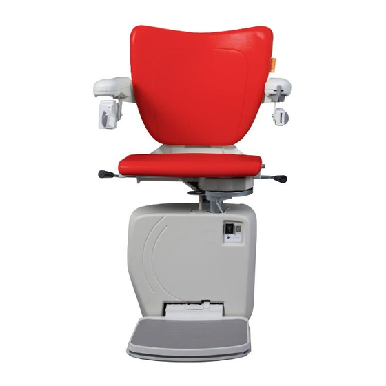
HANDICARE 4000 ST
Hi, it's me.
I'm stuck on the lift.
Can you help me?
Don't worry,
I'll be there
in a minute
Parti del OTA
Pièces de OTA
OTA teile
OTA onderdelen
Partes del OTA
OTA parts
*AA29144*
A A 2 9 1 4 4
I N S T R U C T I O N
INSTRUCCIÓN
INSTRUCTIE
ANLEITUNG
INSTRUCTION
ISTRUZIONE
ES
I T
NL
FR
US
DE
EN
Advertisement

Related Manuals for Handicare 4000 ST


Summary of Contents for Handicare 4000 ST
- Page 1 *AA29144* A A 2 9 1 4 4 HANDICARE 4000 ST I N S T R U C T I O N INSTRUCCIÓN INSTRUCTIE ANLEITUNG INSTRUCTION ISTRUZIONE Hi, it’s me. I’m stuck on the lift. Can you help me? Don’t worry, I’ll be there...
-
Page 2: Tools Required
KIT: AA29144 TOOLS REQUIRED Pz 2 2 mm 3 mm Torx T20 42 mm INSTRUCTION 11P00266 Electro Static Discharge 1 OTA INSTRUCTION... - Page 3 EXPLANATION Only a technician certified for this lift should service this lift (for more detailled information about the required competence see the installation manual). The latest instructions for the lift and instructions for options are available for download at www.handicarepartners.com. [1] Check that all the components of the concerning kit are present.
- Page 4 3 OTA INSTRUCTION...
- Page 5 EXPLANATION [2]Unscrew the top cover of the armrest{A}. Remove the top cover{B}. Remove the bottom cover{C}. [3]Position the new bottom cover of the armrest. [4]Fit the microphoneholder{A}. Install the microphone{B}. Fit the cap{C}. [5]Guide the OTA loom through the arm- and backrest{B}. If needed remove first the backrest cover{A}. Fasten the looms with tiewraps{C}.
- Page 6 Ph 3 5 OTA INSTRUCTION...
- Page 7 EXPLANATION [7]Connect the loom with the microphone{A}. Connect the loom with the push button{B}. [8]Install the top cover of the armrest{A}. Fasten the cover{B}. [9]Put any excess wiring into the back cover cavity {A}.Position the back cover{B}. Do not squeeze the wiring. [10]Fasten the back cover.
- Page 8 3 mm 7 OTA INSTRUCTION...
- Page 9 EXPLANATION [11]Loosen the rivets(6x){A} and screws(2x){B} and remove the front cover{C}. [12]Unscrew the top cover{A}. Remove the cover{B}. [13]Disconnect the two wires of the battery. [14]Disconnect the battery wires from the mainboard. [15]Disconnect the battery wires from the on/-off switch. [11]Maak de pluggen (6x){A} en schroeven (2x){B} los en verwijder de voorkap{C}.
- Page 10 Push button Antenna Orange LED 2 Orange LED 1 Power Microphone/speaker SIM card 9 OTA INSTRUCTION...
- Page 11 EXPLANATION [16]Connect the new battery loom{A} and put the wiring nicely behind the batteries{B}. Note: do not connect the loom to the OTA print yet. [17]Install the SIM card{A}. Press the print against the battery holder{B}. [18]Connect the OTA loom the print{A}. Connect the OTA switch loom to the print{B}. [16]Sluit de nieuwe accukabel aan{A} en leg de bedrading netjes achter de accu’s{B}.
- Page 12 42 mm 11 OTA INSTRUCTION...
- Page 13 EXPLANATION [19]Connect the wire of the antenne to the OTA print {A}. Fit the antenne on the back cover of the power pack {B}. [20]Guide the OTA loom{armrest part} through the chair and chair axle, guide the OTA loom{print part} behind the seat stem{A}.
-
Page 14: Push Button
CLICK! SIM card Microphone/speaker Power Antenna Push button Orange LED 1 Orange LED 2 13 OTA INSTRUCTION... - Page 15 EXPLANATION [23]Fit thespeaker+holder in the 42 mm-hole on the front cover. [24]Connect the speaker loom. [25]Connect the new battery loom to the mainboard at the indicated positions{A}. Connect the new battery loom to the on/-off switch{B}. Connect the new battery loom to the OTA print{C}. The green LED on the OTA print will blink once.
-
Page 16: Program With App
3 mm 2 2 9 3 27 Hi, it’s me. Can you hear me? Numbers: tel. 1: ..tel. 2: ..tel. 3: ..tel. 4: ..tel. 5: ..Perfect, I understand you loud and clear Numbers: tel. 1: ..tel. - Page 17 EXPLANATION [26]Refit the cover {A} and tighten the screws {B}. Be carefull with the wiring. [27]Reinstall the front cover{A} and secure with the rivets(6x){B} and screws(2x){C}. [28]Using the APP on the phone, install the three telephone numbers to be called in case of emergency. And also the press-in time, before the OTA is activated, can be adjusted with the APP.
- Page 20 Only a certified technician should install this kit. The latest instructions of the lift and instructions for options are available for download at www.handicarepartners.com. Partes del OTA Handicare 4000 ST Este manual contiene: Este kit solo lo debe instalar un técnico cualificado. Las últimas instrucciones del salvaescaleras y las instrucciones para las diversas opciones están disponibles para su descarga en www.handicarepartners.com.
Need help?
Do you have a question about the 4000 ST and is the answer not in the manual?
Questions and answers