Advertisement
Quick Links
Installation and Operation Instructions
Please read all instructional literature carefully and thoroughly before starting.
GENERAL
MISUSE OF THIS PRODUCT MAY CAUSE DAMAGE
TO EQUIPMENT OR PERSONAL INJURY. THESE
INSTRUCTIONS MUST BE THOROUGHLY READ AND
UNDERSTOOD BEFORE DEVICE IS INSTALLED.
PRIOR TO INSTALLATION, CHECK THE WETTED PARTS
MATERIAL FOR COMPATIBILITY TO THE PROCESS MEDIA.
Cert number
E42272-19910115
Applicable Area
North America
UL Listed (400 and 402 Series)
Markings
UL Recognized (403 Series)
Applicable Standards
UL 508; CSA-C22.2 No. 14
Cert number
DEMKO 11 ATEX 1105261X
Applicable Area
Europe (EU)
II 1 G Ex ia IIC T6 Ga
Markings
-50°C ≤ Ta ≤ +60°C
Applicable Standards
EN IEC 60079-0; EN 60079-11
Cert number
IECEx UL 14.0075X
Applicable Area
International
Ex ia IIC T6 Ga
Markings
-50 °C ≤ Ta ≤ +60 °C
Applicable Standards
IEC 60079-0; IEC 60079-11
Cert number
FM Project 3021135
Applicable Area
United States of America
Markings
FM Approved
Applicable Standards
FM 3510
ATEX AND IEC SPECIFIC CONDITIONS OF USE: ENCLOSURE
CONTAINS ALUMINUM. CARE MUST BE TAKEN TO AVOID
IGNITION HAZARD DUE TO IMPACT OR FRICTION.
PROOF PRESSURE * LIMITS LISTED ON NAMEPLATE MUST
NEVER BE EXCEEDED, EVEN BY SURGES IN THE SYSTEM.
OCCASIONAL OPERATION OF UNIT UP TO PROOF
PRESSURE IS ACCEPTABLE, E.G., START-UP AND TESTING.
CONTINUOUS OPERATION SHOULD NOT EXCEED THE
DESIGNATED OVER RANGE ** OR MAXIMUM WORKING
PRESSURE *** RANGE.
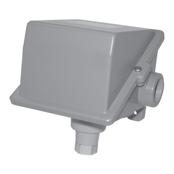
400 Series
Type H400, H402, H403, J400, J402, J403 (Pressure Switch)
Type H400K, H402K, J400K, J402K (Differential Pressure Switch)
Refer to the final page for the Warranty.
*
Proof Pressure - the maximum pressure to which a pressure sensor
may be occasionally subjected, which causes no permanent damage
(e.g., start-up, testing). The unit may require re-gapping.
**
Over Range Pressure - the maximum pressure to which a pressure
sensor may be continuously subjected without causing damage and
maintaining set point repeatability.
***
Working Pressure Range - the pressure range in which two opposing
sensors can be safely operated and still maintain set point, provided the
difference in pressure between the low and high sides does not exceed
the designated adjustable range.
THIS PRODUCT DOES NOT HAVE ANY FIELD
REPLACEABLE PARTS. ANY SUBSTITUTION OF
COMPONENTS SHALL INVALIDATE AGENCY
CERTIFICATION(S).
DEVICE MUST NOT BE ALTERED OR MODIFIED AFTER
SHIPMENT. CONSULT UE IF MODIFICATION IS NECESSARY.
The 400 Series pressure and differential pressure
switches are activated when a bellows, diaphragm
or piston sensor responds to a pressure change.
This response, at a pre-determined set point or
set points, actuates one, two or three snap-acting
switch(es), converting the pressure signal into an
electrical signal. Device set point(s) may be varied
by turning the internal calibrated dial and pointer
(H types) or internal adjustment screw (J types) (See
Part II - Adjustments). Please refer to the datasheet
for product specifications. Date code format on
nameplate is "YYWW" for year and week.
Part I - Installation
•
Flathead screwdriver
•
Hammer (for alternate wire knockouts)
•
Adjustable wrench
Mounting
INSTALL DEVICE WHERE SHOCK, VIBRATION AND
TEMPERATURE FLUCTUATIONS ARE MINIMAL. DO NOT
INSTALL DEVICE IN AMBIENT TEMPERATURES THAT
EXCEED PUBLISHED LIMITS ON THE NAMEPLATE.
DEVICE SHOULD BE MOUNTED TO PREVENT
MOISTURE FROM ENTERING THE ENCLOSURE.
VERTICAL MOUNTING IS RECOMMENDED.
1
IMP400 15
Advertisement

Related Manuals for United Electric Controls 400 Series


Summary of Contents for United Electric Controls 400 Series
- Page 1 DEVICE MUST NOT BE ALTERED OR MODIFIED AFTER SHIPMENT. CONSULT UE IF MODIFICATION IS NECESSARY. Cert number DEMKO 11 ATEX 1105261X The 400 Series pressure and differential pressure Applicable Area Europe (EU) switches are activated when a bellows, diaphragm II 1 G Ex ia IIC T6 Ga Markings or piston sensor responds to a pressure change.
- Page 2 If lead wires are supplied, color coding is as follows: CONSIDER THE USE OF A PRESSURE SNUBBER IF SEVERE PRESSURE SURGES ARE EXPECTED. Manual Reset (Option 1530) 400 & 400K 402 & 402K FOR PRESSURE MODELS, MOUNT VIA PRESSURE CONNECTION. ALWAYS USE A WRENCH ON PRESSURE Switch 3 Switch 1 Switch 2...
- Page 3 Special Instructions for Models 520-535 Part II - Adjustments ❶ Switch #2 should be set first, and to the highest set point. Using a a flathead screwdriver, adjust switch #2 by turning the slotted adjustment screw (see Figure 3) clockwise to raise set •...
-
Page 4: Recommended Practices
Setting the adjustable deadband switch: ❶ Determine rise or fall set point or set points and deadband. HIGH ❷ Adjust each fall set point by turning the adjustment screw clockwise to raise each set point or counterclockwise to lower each set point (see Figure 2). The fall setting is constant. ❸... -
Page 5: Differential Pressure
PRESSURE 1/4 NPT 1/2 NPT 1/4 NPT 1/4 NPT Models 126-164 Models S126B-S164B Models 270-376 Models 440-454, 550-555, 570-572 (154 mm) (154 mm) 1.94 (49,3 mm) 1/4 NPT 1/2 NPT 1/2 NPT Model 610-614 Models 520-525 Models 530-535 DIFFERENTIAL PRESSURE (154 mm) (94 mm) 1.75... -
Page 6: Terms And Conditions Of Sale
French Warnings Translations Page Warning Text Texte d’Avertissement MISUSE OF THIS PRODUCT MAY CAUSE DAMAGE TO EQUIPMENT OR Une mauvaise utilisation de cet appareil peut endommager l’équipement PERSONAL INJURY. THESE INSTRUCTIONS MUST BE THOROUGHLY READ ou provoquer des blessures corporelles. Ces consignes doivent être lues AND UNDERSTOOD BEFORE UNIT IS INSTALLED.
Need help?
Do you have a question about the 400 Series and is the answer not in the manual?
Questions and answers