Advertisement
Please read all instructional literature carefully and thoroughly before starting. Refer to the final page for the listing of Recommended
Practices, Liabilities and Warranties. All Warnings are translated to French and can be found of pages 24 and 25.
GENERAL
MISUSE OF THIS PRODUCT MAY CAUSE EXPLOSION AND PERSONAL INJURY. THESE INSTRUCTIONS MUST BE THOROUGHLY READ AND UNDERSTOOD
BEFORE UNIT IS INSTALLED. SEE THE PRODUCT NAMEPLATE INFORMATION FOR SPECIFIC AGENCY CERTIFICATIONS APPLICABLE TO YOUR PRODUCT.
SUBSTITUTION OF COMPONENTS MAY IMPAIR SUITABILITY FOR USE IN HAZARDOUS LOCATIONS. CABLE GLANDS USED MUST BE RATED FOR A MINIMUM
OF IP66 IN ORDER TO MAINTAIN THE SAME IP RATING.
FOR ZONE HAZARDOUS LOCATIONS, ALL CABLE ENTRY DEVICES SHALL BE CERTIFIED IN TYPE OF EXPLOSION PROTECTION FLAMEPROOF ENCLOSURE "d"
WITH AN IP66 RATING, SUITABLE FOR THE CONDITIONS OF USE AND CORRECTLY INSTALLED. IF CABLES AND CABLE GLANDS ARE NOT USED, A STOPPING
BOX SHALL BE PROVIDED WITHIN 2" OF THE ENCLOSURE. FLAMEPROOF JOINT AND GAP DETAILS ARE PROVIDED ON PAGE 2.
INSTALL UNITS WHERE SHOCK, VIBRATION AND TEMPERATURE FLUCTUATIONS ARE MINIMAL. ORIENT UNIT TO PREVENT MOISTURE FROM ENTERING
ENCLOSURE. USE PROPERLY RATED SEALING FITTINGS FOR ELECTRICAL WIRE ENTRY. DO NOT MOUNT UNIT IN AMBIENT TEMPERATURES EXCEEDING
PUBLISHED LIMITS. THIS IS ESPECIALLY CRITICAL FOR LOCAL MOUNT TEMPERATURE UNITS. USE OF A SHROUD IS RECOMMENDED WHERE DIRECT SUNLIGHT
AND RAIN MAY COME IN CONTACT WITH THE ENCLOSURE.
DURING INSTALLATION, MARK THE BOX NEXT TO EACH PROTECTION METHOD ON THE NAMEPLATE THAT APPLIES TO YOUR APPLICATION.
THIS EQUIPMENT IS CERTIFIED IN ACCORDANCE WITH THE REQUIREMENTS OF THE FOLLOWING APPLICABLE STANDARDS (SEE TABLE 1) AND
IS SUITABLE FOR USE IN NON-HAZARDOUS AND THE FOLLOWING HAZARDOUS LOCATIONS, AND IS ATEX AND IECEX CERTIFIED SUITABLE FOR
APPROPRIATE USE IN GAS AND DUST ZONE 1 APPLICATIONS.
Model 1XTXSW,
N. America
1XTX00
Cert Number:
UL File E226592
Applicable
UL 1203, UL 60079-0, UL 60079-1, UL 61010-1, UL
Standards
50, UL 50E, CSA C22.2 No. 25, CSA C22.2 No. 60079-
0:11, CSA C22.2 No. 60079-1:11, CSA C22.2 No.
61010-1-12, CSA C22.2 No. 94.01-07, CSA C22.2 No.
94.2-07, CSA C22.2 No. 30
Suitable for
Class I, Div. 1, Groups A, B, C & D
appropriate use in:
Class II, Div. 1 Groups E, F & G
Class III
Class I, Zone 1 AEx db IIC T3/T5*
Ex d IIC T3/T5*
Cert number:
UL File E226592
Applicable
UL-60079-0, UL 60079-15, ISA 12.12.01, CSA C22.2
Standards
No. 213, CSA C22.2 No. 60079-0:11, CSA C22.2 No.
60079-15:12, CSA C22.2 No. 157-92
Suitable for
Class I, Div. 2, Groups A, B, C & D
appropriate use in:
Class II, Div. 2 Groups F & G
Class III
Class I, Zone 2 AEx nA IIC T5
Ex nA IIC T5
*Straight pressure sensor models 10-16 and cross-over ranges 06 and 08 have a temperature class of T3, all others T5
One Series Electronic Pressure and
Temperature HART Enabled
Transmitter-Switch
Loop-Powered, Flameproof, and
Non-Incendive Models: 1XTXSW, 1XTX00
Flameproof
Non-Incendive
N. America
IM_1XTXSW-08
www.ueonline.com
U N I T E D E L E C T R I C
C O N T R O L S
Installation and Maintenance
Instructions
Europe
DEMKO 09 ATEX 0813748X
EN 60079-0: 2012 + A11:2013
EN 60079-1:2014
EN 60079-31:2014
II 2 G Ex db IIC T3/T5* Gb
II 2 D Ex tb IIIC T90°C Db
IP66
-40°C ≤ TAMB ≤ +80°C
Europe
DEMKO 15 ATEX 1483
EN 60079-0: 2012 + A11:2013
EN 60079-15:2010
II 3 G Ex nA IIC T4* Gc
IM_1XTXSW-08
International
IECEx UL 08.0017X
IEC 60079-0, Ed.6 (2011-06)
+ Corr.1 (2012-01) + Corr.2
(2013-12)
IEC 60079-1:Ed.7
IEC 60079-31:Ed.2
Ex db IIC T3/T5* Gb
Ex tb IIIC T90°C Db
IP66
-40°C ≤ TAMB ≤ +80°C
International
IECEx UL 08.0017X
IEC 60079-0, Ed.6 (2011-06) +
Corr.1 (2012-01) + Corr.2
IEC 60079-15:Ed.4
Ex nA IIC T4* Gc
Table 1
1
Advertisement
Table of Contents

Related Manuals for United Electric Controls One Series


Summary of Contents for United Electric Controls One Series
- Page 1 IM_1XTXSW-08 One Series Electronic Pressure and Temperature HART Enabled Transmitter-Switch U N I T E D E L E C T R I C Loop-Powered, Flameproof, and C O N T R O L S Non-Incendive Models: 1XTXSW, 1XTX00 Installation and Maintenance Instructions Please read all instructional literature carefully and thoroughly before starting.
- Page 2 Repeatability rivals that of a process transmitter, with a 0.1% of full range while the switches set point and deadband (hysteresis) are fully programmable over the entire range of the sensor. Reaction time for the One Series to a process change is typically 100 mS or less.
-
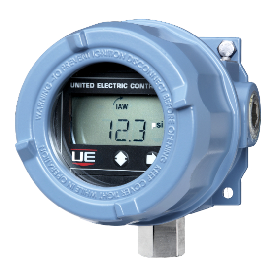
Page 3: Alarm Condition
DISPLAY FEATURES AND DIAGNOSTICS The One Series features a large, easy to read LCD display (See Figure 1). It is used for three main purposes: process indication, programming and switch status/troubleshooting. - Page 4 FOR PRESSURE AND LOCAL TEMPERATURE MODELS ALWAYS HOLD A WRENCH ON THE SENSOR HOUSING HEX WHEN MOUNTING DEVICE. DO NOT TIGHTEN BY TURNING ENCLOSURE, THIS WILL DAMAGE THE CONNECTION BETWEEN THE SENSOR AND HOUSING. FOR DIFFERENTIAL PRESSURE MODELS (ESPECIALLY LOW RANGE MODELS), MOUNT THE SENSOR LEVEL TO MINIMIZE ANY PRESSURE READING OFFSETS.
- Page 5 PART II - WIRING Removing the One Series Enclosure Cover and Display Module TO PREVENT ELECTROSTATIC DISCHARGE WIPE DOWN COVER AND ENCLOSURE OF ANY DUST BUILD-UP BEFORE REMOVING COVER. DISCONNECT ALL SUPPLY CIRCUITS BEFORE WIRING DEVICE. WIRE DEVICE IN ACCORDANCE WITH LOCAL AND NATIONAL ELECTRICAL CODES.
-
Page 6: Wiring Diagrams
(see Figure 6, Page 7). Polarity must be observed. This loop connection powers the entire One Series, including the actuation of both solid-state relays (SW1 & SW2) and the IAW OUTPUT signal. The bi-directional relays are connected via TB2 and ®... -
Page 7: Power Options
Power Supply 24 VDC The One Series may also be powered by direct connection to a 20 – 40 VDC power supply. All device functions, including SW1, SW2 and IAW™ OUTPUT are powered. In this configuration, the analog 4-20 mA output is disabled. - Page 8 For Bench Testing, connect the One Series to a power supply and a load resistor (see Figure 10). A voltmeter across the 250 Ω resistor can be used to measure the current in the loop ( Iloop = Vresistor / 250 ). At 4 mA the voltmeter will read 1 volt and at 20 mA the meter will read 5 volts.
-
Page 9: Fault Current
Output to the fail safe state and the SW1 and SW2 relays to the as-configured tripped state. In addition to the ® discrete outputs, the One Series includes a NAMUR NE 43 standard 4-20 mA output that outputs ≤ 3.6 mA in a fault condition. No Fault Displayed *21.0 mA only when the temperature... -
Page 10: Basic Programming
Programming of the One Series is accomplished using the two buttons on the faceplate (labeled 2 and g see Figure 12). Stepping down through the main menu using the left 2 button, you can access the various commands of the One Series software menu. The right button is then used to move into the command submenu for setting up or modifying the parameters. -
Page 11: Basic Features
Press the right g button to select the mode and move on to the set point. SP will appear. NOTE: The set point is the process value at which the One Series opens or closes the SW1 and SW2 switch. The Set Point is fully programmable throughout the operating range of the sensor as noted on the device nameplate. -
Page 12: Switch Mode
Resetting the Maximum & Minimum Values The One Series continuously captures the readings from the sensor and stores one minimum and maximum value since the last time they were reset. The values can be viewed at any time by removing the enclosure cover and pushing the left 2 button. The display will scroll the values and then return to the Process Display mode. -
Page 13: Advanced Features
Adjusting Display Offset The One Series is factory calibrated to 0.25% of the sensor’s maximum range at room temperature. In some installations, it may be necessary to adjust the display’s offset due to the range and position of the sensor. Chemical seals with long capillaries combined with low maximum range sensors are a common cause of offset error. - Page 14 When latch mode is on (set), the Switch changes state when the set point is crossed and remains latched until the Switch is manually reset by the user or the One Series is power cycled.
- Page 15 Press the right g button to enter the time constant and return to main menu. NOTE: The One Series typically responds to a process value change in less that 100 milliseconds when the Filter is set to off. Using this feature can lengthen the overall response time of the One Series for certain types of process value changes (pressure spikes).
- Page 16 DISPLAY MODULE CALIBRATION These serial numbers must match for proper operation. NOTE: Do not replace the One Series display module or pres- sure sensor. Swapping these amongst devices will cause a mis-match between the stored sensor calibration data and the pressure sensor.
- Page 17 HART Commands: ® All of the configurable features of the One Series that were detailed in the previous pages can be performed using a HART version 7 compatible ® communicator such as those manufactured by Yokogawa, Meriam and Emerson. The One Series 1XTXSW and 1XTX00 provide the latest available...
- Page 18 HART Commands Cont. Command Description Type Write Number of Response Preambles Common Practice Lock Device Common Practice Read Lock Device State Common Practice Write Field Stats Information Device Specific Overwrites the Max and Min values from the device. Read Field Stats Information Device Specific Reads the current Max and Min values from the device.
- Page 19 A list of fault conditions are shown below in table 6. If a fault message appears on the One Series display, a fault code can be obtained by pressing both keypad buttons 2g simultaneously. Please provide this code if calling UE Inside Sales for assistance.
-
Page 20: Troubleshooting
One Series model. Electronic switches cannot be properly tested with an ohmmeter. Instead, measure the voltage drop across the switch connected to the intended load to determine if it is open or closed. A properly functioning One Series electronic switch will exhibit the following voltage levels (see Table 8). - Page 21 Sets Digit and moves to the next PLUG 1MIN PORT 8888 24HR If OFF is selected, Set Window pressing will return to menu PLUG One Series Un-shaded = Display Toggles PORT Programming > RESET 8888 CLR? Flowchart TRIP CNT 1&2 DELAY...
-
Page 22: Dimensional Drawings
DIMENSIONAL DRAWINGS 3/4” - 14 NPT 3/4” - 14 NPT CONDUIT PORTS CONDUIT PORTS 5.7” 6.1” [144.78] [154.94] 5.3” 5.4” [134.62] [137.16] [134.62] [137.16] 1”-20 NPT 1”-20 NPT SENSOR PORT SENSOR PORT GAGE PRESSURE DIFFERENTIAL PRESSURE 3/4” - 14 NPT 3/4”... -
Page 23: Sensor Options
SENSOR OPTIONS Pressure Sensors Dual Seal with Gage Pressure Gauge Pressure Differential Pressure Sensor (Option M041) 1.06 [26.9mm] 1.06 [221mm] [26.9mm] 8.70” 1/4”-18 NPT (MALE) BOTH ENDS 1/2”-14 NPT (FEMALE) [76.2mm] DUAL SEAL ENCLOSURE 1/8" NPT [72.6mm] [61.9mm] Temperature Sensors ANNUNCIATION 2.86”... - Page 24 FRENCH WARNING TRANSLATIONS Page Warning Text Texte d’advertissement Misuse of this product may cause explosion Utilisation abusive de ce produit peut causer une explosion et des blessures. and personal injury. These instructions must be Ces instructions doivent être soigneusement lues et comprises avant l’ appareil thoroughly read and understood before unit is est installé.
- Page 25 FRENCH WARNING TRANSLATIONS CONT. Page Warning Text Texte d’advertissement Never insert any object into the pressure sensor Ne jamais insérer un objet dans l’orifice du capteur de pression. Les dommages opening. Damage to the sensor will result, affect- à la membrane de capteur se traduira, à affecter la précision. ing accuracy.
- Page 26 24 months from the date of manufacture by the Seller (36 months for the Spectra 12 and One Series products; 18 months for Temperature Sensors). Seller shall not be obligated under...
Need help?
Do you have a question about the One Series and is the answer not in the manual?
Questions and answers