Advertisement
Quick Links
Installation and Operation Instructions
Please read all instructional literature carefully and thoroughly before starting.
GENERAL
MISUSE OF THIS PRODUCT MAY CAUSE DAMAGE
TO EQUIPMENT OR PERSONAL INJURY. THESE
INSTRUCTIONS MUST BE THOROUGHLY READ AND
UNDERSTOOD BEFORE DEVICE IS INSTALLED.
PRIOR TO INSTALLATION, CHECK THE WETTED PARTS
MATERIAL FOR COMPATIBILITY TO THE PROCESS MEDIA.
Cert number
20181026-E42272
Applicable Area
North America
Markings
UL Recognized
Applicable Standards
UL 508; C22.2 No. 14
Cert number
DEMKO 11 ATEX 1105261X
Applicable Area
Europe (EU)
Markings
II 1 G Ex ia IIC T6 Ga
Applicable Standards
EN IEC 60079-0; EN 60079-11
Cert number
IECEx UL 14.0075X
Applicable Area
International
Ex ia IIC T6 Ga
Markings
-50 °C ≤ Tamb ≤ +60 °C
Applicable Standards
IEC 60079-0; IEC 60079-11
ATEX AND IEC SPECIFIC CONDITIONS OF USE: ENCLOSURE
CONTAINS ALUMINUM. CARE MUST BE TAKEN TO AVOID
IGNITION HAZARD DUE TO IMPACT OR FRICTION.
PROOF PRESSURE * LIMITS LISTED ON NAMEPLATE MUST
NEVER BE EXCEEDED, EVEN BY SURGES IN THE SYSTEM.
OCCASIONAL OPERATION OF UNIT UP TO PROOF
PRESSURE IS ACCEPTABLE, E.G., START-UP AND TESTING.
CONTINUOUS OPERATION SHOULD NOT EXCEED THE
DESIGNATED OVER RANGE ** OR MAXIMUM WORKING
PRESSURE *** RANGE.
*
Proof Pressure - the maximum pressure to which a pressure sensor
may be occasionally subjected, which causes no permanent damage
(e.g., start-up, testing). The unit may require re-gapping.
**
Over Range Pressure - the maximum pressure to which a pressure
sensor may be continuously subjected without causing damage and
maintaining set point repeatability.
***
Working Pressure Range - the pressure range in which two oppos-
ing sensors can be safely operated and still maintain set point provided
the diff erence in pressure between the low and high sides does not
exceed the designated adjustable range.
Buy: www.ValinOnline.com | Phone 844-385-3099 | Email: CustomerService@valin.com
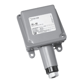
100 Series
Type H100 (Pressure Switch)
Type H100K (Diff erential Pressure Switch)
Refer to the final page for the Warranty.
THIS PRODUCT DOES NOT HAVE ANY FIELD
REPLACEABLE PARTS. ANY SUBSTITUTION OF
COMPONENTS SHALL INVALIDATE AGENCY
CERTIFICATION(S).
DEVICE MUST NOT BE ALTERED OR MODIFIED AFTER
SHIPMENT. CONSULT UE IF MODIFICATION IS NECESSARY.
The 100 Series pressure and diff erential pressure
switches are activated when a bellows, diaphragm or
piston sensor responds to a pressure change. This
response, at a pre-determined set point, actuates a
single snap-acting switch, converting the pressure
signal into an electrical signal. Control set point may
be varied by turning the internal adjustment hex. (See
Adjustment - PART II). Please refer to the datasheet
at www.ueonline.com for product specifi cations.
Date code format on nameplate is "YYWW" for year
and week.
Part I - Installation
•
Adjustable wrench
•
Screwdriver
•
Hammer (for alternate wire knockouts)
Mounting
INSTALL DEVICE WHERE SHOCK, VIBRATION AND
TEMPERATURE FLUCTUATIONS ARE MINIMAL. DO NOT
INSTALL DEVICE IN AMBIENT TEMPERATURES THAT
EXCEED PUBLISHED LIMITS ON THE NAMEPLATE.
DEVICE SHOULD BE MOUNTED TO PREVENT
MOISTURE FROM ENTERING THE ENCLOSURE.
VERTICAL MOUNTING IS RECOMMENDED.
CONSIDER THE USE OF A PRESSURE SNUBBER IF
SEVERE PRESSURE SURGES ARE EXPECTED.
FOR PRESSURE MODELS, MOUNT VIA PRESSURE
CONNECTION. ALWAYS USE A WRENCH ON PRESSURE
CONNECTION HEX. DO NOT TIGHTEN BY TURNING
THE ENCLOSURE AS THIS WILL DAMAGE THE SENSOR
AND WEAKEN WELDED JOINTS.
1
IMP100 13
Advertisement

Related Manuals for United Electric Controls 100 Series


Summary of Contents for United Electric Controls 100 Series
- Page 1 DEVICE MUST NOT BE ALTERED OR MODIFIED AFTER SHIPMENT. CONSULT UE IF MODIFICATION IS NECESSARY. PRIOR TO INSTALLATION, CHECK THE WETTED PARTS The 100 Series pressure and diff erential pressure MATERIAL FOR COMPATIBILITY TO THE PROCESS MEDIA. switches are activated when a bellows, diaphragm or piston sensor responds to a pressure change.
- Page 2 FOR DIFFERENTIAL PRESSURE MODELS, MOUNT ALL MODELS HAVE A TWO-PIECE ADJUSTABLE USING A WRENCH ON LOW AND HIGH SIDE PRESSURE PLUNGER (SEE FIGURE 1). THIS FEATURE IS CONNECTION HEX OR MOUNT AGAINST A RIGID SUPPORT CHARACTERIZED BY A 3/16” HEX SCREW INSTALLED THEN CONNECT LOW AND HIGH PRESSURE PORTS.
-
Page 3: Recommended Practices
Models Flats Approx. Gap AFTER COMPLETING SETTING ADJUSTMENT, BE SURE TO REINSTALL ENCLOSURE COVER. 171-174 2 to 2 1/2 .0085 to .0105” 183-194 1 to 1 1/2 .004 to .006” 483-494 1 to 1 1/2 .004 to .006” Re-Gapping Procedure (refer to Figure 1) 358-376 5 to 6... - Page 4 1/2 NPT 1/2 NPT 1/2 NPT 1/4 NPT Models 183-186, 483-486 Models 188-194,488-494 Models 218-376, 610-706, Models 171-174 15623-15736, 15884 1/8 NPT (Female) (Low & High) 1 15/16 1 11/16 (49.2 mm) (42.9 mm) 1/2 NPT 1/2 NPT (152.4 mm) (152.4 mm) (152.4 mm) Models 520-525, 15737...
- Page 5 French Warnings Translations Page Warning Text Texte d’Avertissement MISUSE OF THIS PRODUCT MAY CAUSE DAMAGE TO EQUIPMENT OR Une mauvaise utilisation de cet appareil peut endommager l’équipement PERSONAL INJURY. THESE INSTRUCTIONS MUST BE THOROUGHLY READ ou provoquer des blessures corporelles. Ces consignes doivent être lues AND UNDERSTOOD BEFORE UNIT IS INSTALLED.
-
Page 6: Limited Warranty
LIMITED WARRANTY LIMITATION OF SELLER’S LIABILITY Seller warrants that the device hereby purchased is, upon Seller’s liability to Buyer for any loss or claim, including liability delivery, free from defects in material and workmanship and incurred in connection with (i) breach of any warranty that any such device which is found to be defective in such whatsoever, expressed or implied, (ii) a breach of contract, (iii) workmanship or material will be repaired or replaced by Seller...
Need help?
Do you have a question about the 100 Series and is the answer not in the manual?
Questions and answers