Table of Contents
Advertisement
Quick Links
Please read all instructional literature carefully and thoroughly before starting. Refer to the final page for the listing of
Recommended Practices, Liabilities and Warranties.
GENERAL (MOUNTING and WIRING)
MISUSE OF THIS PRODUCT MAY CAUSE PERSONAL INJURY. THESE INSTRUCTIONS MUST BE THOROUGHLY
READ AND UNDERSTOOD BEFORE UNIT IS INSTALLED. SEE PRODUCT NAMEPLATE INFORMATION FOR SPE-
CIFIC AGENCY CERTIFICATIONS APPLICABLE TO YOUR PRODUCT.
CONTINUOUS OPERATION SHOULD NOT EXCEED THE DESIGNATED OVER RANGE PRESSURE OR WORKING
PRESSURE RANGE STATED WITHIN THE LITERATURE AND ON DEVICE NAMEPLATE.
INSTALLATION
MOUNTING
FOR PRESSURE AND LOCAL TEMPERATURE MODELS, ALWAYS HOLD A WRENCH ON THE SENSOR HEX WHEN
MOUNTING UNIT. DO NOT TIGHTEN BY TURNING ENCLOSURE. THIS WILL DAMAGE THE CONNECTION BETWEEN
THE SENSOR AND HOUSING.
INSTALL UNITS WHERE SHOCK, VIBRATION AND TEMPERATURE FLUCTUATIONS ARE MINIMAL. ORIENT UNIT
MAKING SURE THAT THE ELECTRICAL CONDUIT CONNECTION IS NOT FACING UP, TO PREVENT MOISTURE FROM
ENTERING ENCLOSURE. DO NOT MOUNT UNIT IN AMBIENT TEMPERATURES EXCEEDING PUBLISHED LIMITS.
FOR DIFFERENTIAL PRESSURE MODELS (ESPECIALLY LOW RANGE UNITS), MOUNT THE SENSOR LEVEL TO MINI-
MIZE ANY PRESSURE READING OFFSETS. THE OFFSET COMMAND MAY BE USED TO ZERO THE DISPLAY (SEE
PAGE 5 FOR ADDITIONAL INFORMATION).
Excela is rated for both indoor and outdoor operation, IP66 and Nema 4X, with a temperature rating of -40°C to 71°C
•
Surface mount the unit using the two (2) 1/4" clearance holes in the mounting ears
•
Pressure and Differential Pressure units can be mounted directly to process connections if they are able to sup-
port the product.
•
To pipe mount: Thread the pressure connection onto the pressure port. Use a wrench on the hex pressure con-
nection to tighten. Test for leaks. On Differential Pressure models, the Low (L) side pressure must NOT exceed the
high (H) side pressure.
•
Allow space in front of the unit to access the programming function of the product.
Over Range Pressure:
The maximum pressure to which a pressure sensor may be continuously subjected to without causing damage and maintaining setpoint repeatability.
Max Working Pressure:
The maximum that can be applied to both process ports simultaneously without affecting sensor performance. The low (L) side pressure must NOT
exceed the high (H) side pressure. Damage to the sensor may result.
WARNING: NEVER INSERT ANY OBJECT INTO THE PRESSURE SENSOR OPENING. DAMAGE TO THE SENSOR WILL
RESULT, AFFECTING ACCURACY.
Excela™ Electronic Pressure and
Temperature Switches
Discrete Input Powered
IM_1GSW-02
www.ueonline.com
U N I T E D E L E C T R I C
C O N T R O L S
Installation and Maintenance
Instructions
1-1/16" wrench for sensor hex fitting
screwdriver for mounting bolts
2 mounting bolts (1/4" Max.)
IM_1GSW-02
Tools Required
1
Advertisement
Table of Contents

Related Manuals for United Electric Controls Excela 1GSWLL


Summary of Contents for United Electric Controls Excela 1GSWLL
- Page 1 IM_1GSW-02 Excela™ Electronic Pressure and Temperature Switches U N I T E D E L E C T R I C Discrete Input Powered C O N T R O L S Installation and Maintenance Instructions Please read all instructional literature carefully and thoroughly before starting. Refer to the final page for the listing of Recommended Practices, Liabilities and Warranties.
- Page 2 Local and Remote Temperature Models For Immersion Sensing: Use of a thermowell is highly recommended to aid in maintenance. Insert the sensor housing (0.25” diameter) into the well ensuring that the housing bottoms out and will be completely immersed in the media (2.5” min.) Secure the sensor using an appropriately sized compression fitting or union connector.
-
Page 3: Alarm Condition
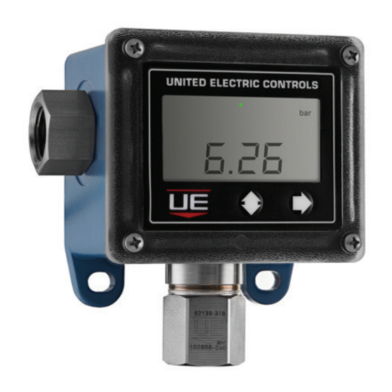
DISPLAY The Excela features a large, easy-to-read display, showing the process condition and the status of the switch. (See program- ming section for a complete description.) Setpoint and minimum/maximum process values can be easily accessed from the front of the unit while in operation. Programming and interrogating the Excela is done through two buttons on the faceplate. The Excela features a large, easy to read LCD display. - Page 4 PROGRAMMING See flowchart on page 8 NOTE: The arrow moves down the menu and the arrow moves to the right for the next selection Basic Programming Menu Unit of measure and set-points Basic Programming To use the product as a basic switch, Excela programming is simple: Video •...
-
Page 5: Latch Mode
OFFSET: Offset adjustment changes the zero point without changing the slope of the calibration line. The Excela is factory calibrated to 0.5% of sensor range at room temperature. In some applications, it may be necessary to re-calibrate the unit in the field. Offset allows the user to enter a positive (“POS”) or negative (“NEG”) offset to the display readings. - Page 6 ACCEPTABLE SUPPLY VOLTAGES AND LOADS FOR EXCELA The charts below provide a range of acceptable power supply voltages (in Volts) and series loads (in Ohms). NOTE: If you need assistance with determining the compatibility of the Excela electronic switch with your PLC, DCS, or relay, we can help.
- Page 7 EXCELA ERROR MESSAGES The Excela diagnostics are capable of detecting many possible error conditions. Some error conditions will clear automatically when the parameter returns to normal; others require the device to be powered down and restarted; and some may require repair or replacement. A list of error conditions are listed below. Possible Corrective Actions Error Condition Probable Causes...
- Page 8 Excela™ Electronic Switch Programming Flowchart Excela Installation Manual Hyperlinks Electronic Switch English Version Programming Flowchart Spanish Version Portuguese Version Display to Scroll: MAX xxxx, MIN xxxx, TRIPS XXX NOTE: while scrolling, pressing the right arrow will clear MAX/MIN/TRIPS values Display to Scroll Setpoints: RISE xxxx, FALL xxxx Both °F...
-
Page 9: Dimensional Drawings
DIMENSIONAL DRAWINGS Model 1GSWLL Gauge Pressure Sensor Model 1GSWLL Differential Pressure Sensor IM_1GSW-02 www.ueonline.com... - Page 10 Model 1GSWLL Temperature Model R Sensor Model 1GSWLL Temperature Model L Sensor IM_1GSW-02 www.ueonline.com...
-
Page 11: Recommended Maintenance Procedures
The Excela is a robust and reliable instrument that requires minimum yearly maintenance. If you have any questions related to this maintenance guide, please contact United Electric Controls at insidesales@ueonline. com or call inside sales at Tel: +1 617-923-6977 for additional information. - Page 12 Warnings: French Translations Page Warning Text Texte d’advertissement Misuse of this product may cause personal injury. These instructions Une mauvaise utilisation de ce produit peut entraîner des blessures. Ces must be thoroughly read and understood before unit is installed. instructions doivent être soigneusement lues et comprises avant l’ appareil See the product nameplate information for specific agency certifica- est installé.
-
Page 13: Limited Warranty
RECOMMENDED PRACTICES AND WARNINGS United Electric Controls Company recommends careful consideration of the following factors when specifying and installing UE pressure and temperature units. Before installing a unit, the Installation and Maintenance instructions provided with unit must be read and understood.
Need help?
Do you have a question about the Excela 1GSWLL and is the answer not in the manual?
Questions and answers