
Related Manuals for Karma Morgan Series


Summary of Contents for Karma Morgan Series
- Page 1 Powered Wheelchair Owner Manual Morgan Series (MRG-Sling Seat/MRG-Captain Seat/MRG-Kiss Seat)
- Page 2 CHANGE WITHOUT NOTICE BY KARMA. WARNING ● As a manufacturer of powered wheelchairs, KARMA endeavors to supply a wide variety of powered wheelchairs to meet the many needs of the user. However, the responsibility of final selection of the type of powered wheelchair to be used by an individual rests solely with the user and his/her healthcare professional capable of making such a selection.
- Page 3 ● For individuals with balance problems, practice mounting and dismounting activities WITH AN ASSISTANT in the presence of a qualified healthcare professional. ● If anti-tippers are standard equipped, DO NOT operate the wheelchair without anti-tippers being installed. Anti-tippers MUST BE attached at all times.
- Page 4 ● DO NOT use parts, accessories or adapters other than those authorized by Karma. Before attempting to sit in or exit the power wheelchair, turn the power OFF. This will ensure that the power wheelchair will not drive. Turn the power OFF while the wheelchair is not in use.
- Page 5 according to ISO 7176-19. Therefore, the MRG series cannot be used as seats in any vehicles. That is, KARMA recommends that users are NOT transported in any vehicle while seated in the wheelchair. In the case of accident or a sudden stop, the user could be thrown from the wheelchair and get injured.
- Page 6 BATTERIES ● The warranty and performance specifications contained in this manual are based on the use of deep cycle sealed lead acid batteries. KARMA strongly recommends their use as the power source for this unit. (Refer to chapter 6) ● Carefully read the battery and charger information prior to installing, servicing or operating your wheelchair.
- Page 7 Extreme caution is advised when it is necessary to move an UNOCCUPIED powered wheelchair up or down stairs. ● Karma recommends disassembling the wheelchair and transporting the components independently up or down stairs. Make sure to use ONLY secure, non-detachable parts on each component for hand-hold supports.
- Page 8 If you cannot contact your dealer, please contact another authorized Karma dealer for service. If all else fails, contact Karma directly via our website or give us a call and we can refer you to your new service provider.
- Page 9 For safety reasons, if there is any risk due to the user's movement in the wheelchair or other environmental factors that might cause the wheelchair to tip or the person on the wheelchair to fall off, Karma recommends that you install anti-tippers, pelvic belt, or other additional safety accessories.
-
Page 10: Table Of Contents
TABLE OF CONTENTS 1. PREFACE ........................1 2. SAFETY ........................... 2 2.1 Before Driving ...................... 2 2.2 Traffic Rules ......................2 2.3 Practice Driving ....................2 2.4 No Passengers ...................... 3 2.5 No Hauling Heavy Goods ................3 2.6 Rain .......................... 3 2.7 While Driving ...................... - Page 11 6.1 Charging the Batteries ................... 63 6.2 Charge the Batteries If Any of the Following Conditions Occurs ... 63 6.3 Be Sure to Precisely Follow the Procedures Listed Below....63 6.4 Charger ........................ 65 6.5 Batteries ....................... 65 6.6 Cleaning the Batteries ..................67 6.7 Replacing the Batteries ..................
-
Page 12: Preface
1.1 This owner's manual includes operation instructions for the aspects of the wheelchair, assembly instructions, and instructions on how to deal with possible accidents. This owner's manual is written for Karma powered wheelchair(s): MRG series (MRG Sling Seat, MRG Captain Seat and MRG KISS seat) 1.2 The symbols used in this manual are explained below. -
Page 13: Safety
2. SAFETY 2.1 Before Driving 2.1.1 The user must be familiar with the use and operation of this wheelchair before driving. 2.1.2 Therefore, please always keep these safety guidelines in mind. 2.1.3 For a visually impaired people, be sure someone accompanies you in case you need assistance. -
Page 14: No Passengers
2.3.4 Be sure you are able to control and operate your wheelchair easily and confidently before you set the speed higher. 2.4 No Passengers KARMA wheelchair is limited to only one single driver. Do not carry passengers (including children) on your wheelchair. 2.5 No Hauling Heavy Goods Do not use this wheelchair to carry or haul heavy goods. -
Page 15: Mobile Phones And Other Electric Equipment
and ice. These conditions may damage your wheelchair. 2.10.2 Avoid roads that are too narrow or by a canal/waterway without any fence/hedge. 2.10.3 Also avoid places where your wheels might get stuck, slip or not have traction. 2.10.4 Do not drive in a gale, at night or in rainy/snowy/foggy/misty weather. These conditions may cause your wheelchair to rust. -
Page 16: Maximum User Weight Limit
2.12.10 Again, descending obstacles should be done perpendicularly. (Figure 2.6) 2.12.11 Karma does not design wheelchairs to take jumps over or off obstacles. Doing so will void your warranty. WARNING ●... -
Page 17: Mrg Series Labeling
2.14 MRG Series Labeling Please carefully read all the labeling on the wheelchair before driving it. Do not remove them. Protect them for future reference. Labeling Location [Circuit Breaker] If this circuit breaker operates, reset it by pushing the button. [Finger-Pinch] Avoid it when flip back the armrest. -
Page 18: Emi/Rfi
CAUTION ● It is very important that you read this information regarding the possible effects of electromagnetic interference on your powered KARMA wheelchair. 3.1 Electromagnetic Interference From Radio Wave Sources 3.1.1 Powered vehicles may be susceptible to electromagnetic interference... -
Page 19: The Sources Of Radiated Emi Can Be Broadly Classified Into
least a 20 V/m immunity level, which would provide useful protection from the more common sources of radiated EMI. This powered vehicle model, with no further modification, has an immunity level of 20 V/m without any accessories. 3.1.2 There are a number of sources of relatively intense electromagnetic fields in our everyday environment. -
Page 20: Powered Vehicle Electromagnetic Interference (Emi)
3.3 Powered Vehicle Electromagnetic Interference (EMI) Because EM energy rapidly becomes more intense as one moves closer to the transmitting antenna (source), the EM fields from hand-held radio wave sources (transceivers) are of special concern. It is possible to unintentionally bring high levels of EM energy too close to the powered vehicle's control system while using these devices. - Page 21 3.4.5 Report all incidents of unintended movement or brake release to your powered vehicle dealer or KARMA, and note whether there was a source of EMI nearby.
-
Page 22: Parts
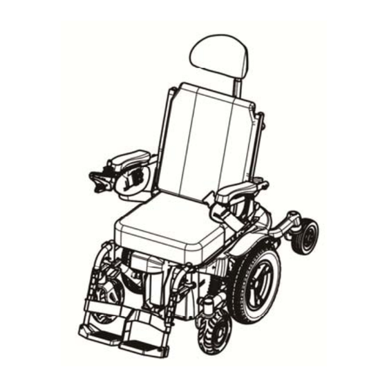
4. PARTS 4.1 MRG with Captain Seat 1. Headrest 6. Freewheel Lever 11. Footrest 2. Captain Seat(Backrest) 7. Controller(Joystick) 12.Calf Support 3. Armrest 8. Pelvic Belt 13. Footplate 4. Rear Wheel 9. Charger Socket 14. Battery Casing 5. Middle Wheel 10. Captain Seat 15. Caster... - Page 23 1. Armrest Adjusting Knob 3. Rear Battery Casing 2. Turn Signal (Optional) 4. Taillight (Optional) CAUTION: ● Standard equipments are subject to change without notice.
-
Page 24: Mrg With Sling Seat
4.2 MRG with Sling Seat 1. Headrest(Optional) 7. Running Brake 12.. Sling Seat 2. Sling Seat (Backrest) lever (Optional) 13.. Footrest 3. Armrest 8. Caster 14. Calf Support 4. Pelvic Belt 9. Side Panel 15. Footplate 5. Rear Wheel 10.Controller(Joystick) 6. Middle Wheel 11. -
Page 25: Mrg With Kiss Seat
4.3 MRG with KISS Seat 1. Headrest(Optional) 5. Rear Wheel 9. Seat 2. Backrest 6. Middle Wheel 10. Footrest 3. Armrest 7. Controller(Joystick) 11. Footplate 4. Pelvic Belt 8. Charger Socket 12. Caster CAUTION: ● Standard equipments are subject to change without notice. -
Page 26: Operation
Anything wheelchair related that requires tools should be done by your authorized Karma service provider. 5.1 Controller Cable Tie Location 5.1.1 The controller for the MRG series is packaged in the carton; after opening the carton, the controller needs to be equipped to the correct position by fastening two screws. -
Page 27: How To Operate Your Wheelchair
5.2 How to Operate Your Wheelchair VR2 Controller:Control Panel With Lighting Control No Actulator With Actulators MRG Control Panel (Figure 5-1) MRG Control Panel (Figure 5-2) 1. Battery Gauge 9. Right Turn Signal Button 2. ON/OFF Button 10. Hazards Indicator 3. - Page 28 detailed below. 5.2.2.1 To lock the wheelchair. 5.2.2.1.1While the control system is switched on, depress and hold the on/off button. 5.2.2.1.2 After one second the control system will beep. Now release the on/off button. 5.2.2.1.3 Deflect the joystick forwards until the control system beeps. 5.2.2.1.4 Deflect the joystick in reverse until the control system beeps.
- Page 29 KARMA dealers. Do not change or adjust the wiring layout of the chair for your safety. ● Please slow down your speed when using it indoor. 5.2.4 Driving Speed 5.2.4.1You can choose between 1 to 5 orange dots in the speed indicator, with 5 being the maximum speed.
- Page 30 5.2.7.1To turn the Headlight/Taillight on, press the Headlight/Taillight Button. Press the Headlight Button again to turn the headlight/taillight off. 5.2.8 Warning Signal(Hazards Light) 5.2.8.1To turn the Hazards Indicator on, press the Hazards Button. Press the Hazards Button again to turn the hazards function off. CAUTION ●...
- Page 31 CAUTION ● If the slope is bigger than 5°, either the tilting or reclining operation can only be allowed in one way direction to drive the seat back to the initial position. ● Once the slope is less than 5°, full operating functions of tilting and reclining be recovered.
- Page 32 5.2.14 Joystick 5.2.14.1 The primary function of the joystick is to control the speed and direction of the wheelchair. The further you push the joystick from the center position the faster the wheelchair will move. When you release the joystick the brakes are automatically applied. 5.2.14.2 If the wheelchair is fitted with actuators, the joystick can also be used to move and select actuators, refer to section 5.5 for more details.
- Page 33 5.2.15 Buttons 5.2.15.1 On/Off Button 5.2.15.1.1The On/Off button applies power to the control system electronics, which in turn supply power to the wheelchair’s motors. Do not use the On/Off button to stop the wheelchair unless there is an emergency. (If you do, you may shorten the life of the wheelchair drive components).
- Page 34 programmed a momentary screen may be displayed when the button is pressed. 5.2.15.4.3 Refer to section 5 for details of the momentary screen. 5.2.15.4.4 Refer to Chapter - Programming for details. 5.2.15.5 Mode Button 5.2.15.5.1 The Mode button allows the user to navigate through the available operating Modes for the control system.
- Page 35 5.2.15.9 Left Indicator Button and LED 5.2.15.9.1 This button activates and de-activates the wheelchair’s left indicator. Depress the button to turn the indicator on and depress the button again to turn it off. 5.2.15.9.2 When activated the left indicator LED will flash in sync with the wheelchair’s indicator(s).
- Page 36 5.2.17 Charger Socket 5.2.17.1 This socket should only be used for charging or locking the wheelchair. Do not connect any type of programming cable into this socket. 5.2.17.2 Refer to section 13 for more details on charging. 5.2.17.3 This socket should not be used as a power supply for any other electrical device.
- Page 37 ● When driving on an incline, the battery indicator light might move up and down. This is normal. ● Even if the batteries are used properly their capacity will decay over time, thereby reducing the drive range (maximum distance traveled per full charge). Thus, when the drive range becomes about 50% of what brand new batteries would offer, it's time to replace them with new batteries.
-
Page 38: How To Adjust Your Wheelchair
● When adjusting the footrest or the footplates, the user's legs should be supported or kept safe from possible injury. 5.3.1 Footrest : The MRG series can be mounted with several types of KARMA footrests. 5.3.1.1 Swing Away and Detach Footrest 5.3.1.1.1To swing away and detach the footrests, pull the swing-away... - Page 39 5.3.1.3 Stump Footrest 5.3.1.3.1 Stump footrest is shown as Figure 5-9 5.3.1.3.2 To swing away and detach the footrests, pull the swing-away lever (Figure 5-10), then you can swing away and/or detach the footrests. (Figure 5-11) It can make transferring in and out of the wheelchair easier.
- Page 40 5.3.1.4.2 To swing away and detach the footrests, pull the swing-away lever (Figure 5-16), then you can swing away and/or detach the footrests. (Figure 5-17) It can make transferring in and out of the wheelchair easier. 5.3.1.4.3 Footrest angle adjustment: 5.3.1.4.4Raise the footrest to an apporpriate angle to accommodate the user's leg position and flexibility.
- Page 41 lever (Figure 5-22), then you can swing away and/or detach the footrests. (Figure 5-23) It can make transferring in and out of the wheelchair easier. 5.3.1.5.3 Calf support adjustment: Use the #5 Allen Key Wrench to loosen the screw and adjust the calf ●...
- Page 42 5.3.2 Footrest Adjustment in Longitudinal (Fore/Aft) Position 5.3.2.1 Captain Seat and Sling Seat: 5.3.2.1.1Please use the #5 Allen Key wrench included in your KARMA Tool Kit to make this adjustment. Remove the screws under the seat (Figure 5-3) adjust the footrest to accommodate the user's leg position (Figure 5-31).
- Page 43 footplate. Adjust the footplate height and re-tighten the bolt. (Figure 5-35) Figure 5-35 5.3.3.2 Tube-in-Center Footplate: 5.3.3.2.1Use the #4 Allen Key Wrench and the #10 box end Wrench to loosen the bolt. (Figure 5-36) Adjust the footplate height and re-tighten the bolt. (Figure 5-37,Figure 5-38) Figure 5-36 Figure 5-37 Figure 5-38...
- Page 44 5.3.3.4 Angle Adjustable Footplate 5.3.3.4.1 Angle Adjustable Footplate is shown as Figure 5-42. 5.3.3.4.2 Use the #4 Allen Key Wrench and the #10 box end Wrench to loosen the bolt. (Figure 5-43) Adjust the footplate height and re-tighten the bolt. 5.3.3.4.3 Use the #5 Allen Key Wrench to loosen the screw.
- Page 45 5.3.4.1 MRG with Sling Seat 5.3.4.1.1In order to position the user's arms and shoulders correctly, the armrests are adjustable in height by 7 cm from 18 cm above the seat rail to 25 cm. Use the #5 Allen Key Wrench from KARMA...
- Page 46 Tool Kit to loosen the height adjustment bolts under the armrest pad (Figure 5-50). Adjust the armrest to the proper height. Finally, re-tighten the bolts. (Figure 5-51) 5.3.4.2 MRG with KISS seat Detachable T-Armrest Set Adjustment 5.3.4.2.1 Detachable T-Armrest set is shown as Figure 5-52 5.3.4.2.2 The whole armrest assembly can be removed by releasing lever A.
- Page 47 5.3.4.2.7 Press the spring button and flip the armrest back. (Figure 5-57) 5.3.4.2.8 When adjusting the whole armrest assembly upwards or downwards, use the #4 Allen Key Wrench and the #10 box end Wrench to loosen the screw used to fixing the armrest bracket. (Figure 5-58) 5.3.4.2.9 When adjusting the armrest pad upwards or downwards, use the #4 Allen Key Wrench to loosen the screw used to fixing the...
- Page 48 Table 6-1 Armrest angle adjustment table ble 6-2 Back pad angle adjustment table Flip-Back Reclining Armrest 5.3.4.2.13 Flip-Back reclining armrest is shown as Figure 5-64 5.3.4.2.14 By pulling the lock pin and turning it in 90 degree, the armrest can be lifted backwards. (Figure 5-65) Figure 5-64 Figure 5-65 5.3.4.2.15 When putting the armrest back to the working position, be sure...
- Page 49 5-66) 5.3.4.2.16 Use the #4 Allen Key Wrench and the #10 box end Wrench to remove the screws. Adjust the armrest height and re-tighten the screws. (Figure 5-67) 5.3.4.2.17 Use the #5 Allen Key Wrench to loosen the screw. Adjust the base block forwards or backwards and re-tighten the screw.
- Page 50 5.3.5 Seat Depth and Seat Width Adjustment MRG with Sling Seat (Seat Depth Adjustment) 5.3.5.1 Use the #13 box end Wrench from KARMA Tool Kit to loosen the two bolts under the seat . Remove the bolts on the other side. (Figure 5-71).
- Page 51 CAUTION ● Adjusting the seat depth will change the center-of-gravity position. For your safety, contact your KARMA wheelchair dealer for adjustment. Figure 5-74 Figure 5-75 Figure 5-76 Figure 5-77 MRG with KISS Seat (Seat Width Adjustment) KISS Seat without Tilt and Recline Options 5.3.5.9 KISS Seat without tilt and recline options is shown as Figure 5-78.
- Page 52 5.3.5.11 Use the #4 Allen Key Wrench to loosen the screws C. (Figure 5-80) 5.3.5.12 Use the #5 Allen Key Wrench to remove the screws D. Move part E and F inwards or outwards to adjust the seat width in order to meet user's needs.
- Page 53 Figure 5-84 Figure 5-85 Figure 5-86 KISS Seat with Reclining Option KISS Seat with recline option is shown as Figure 5-85 5.3.5.16 5.3.5.16.1 The procedures to adjust the the seat width are almost the same as those of KISS seat without tilting and reclineing options except step 5.3.5.17 Befoe adjusting the backsupport width, remove the screws A.
- Page 54 MRG Sling Seat without Tilting Function: 5.3.6.3 The initial seat angle is set at 2°. If the desired seat angle can be 5°, Lossen the screws at both the left side and right side from the lower hole (Figure 5-88) and insert them in the upper hole. MRG KISS Seat with Tilting Option (Including seat height adjustment):...
- Page 55 5.3.6.3.4According to table 5-1, Replace screws on plate plates Ⅳ (A, B, C or D) and plateⅤ(F1, F2, F3, F4, F5 or F6). Re-tighten all screws. (Figure 5-95) 5.3.6.4 Ensure all screw are properly tightened. Figure 5-90 Figure 5-91 Figure 5-92 Table 5‐1 : Kiss seat with tilting function ...
- Page 56 MRG KISS Seat without Tilting Option (Including seat height adjustment): 5.3.6.5 KISS Seat without Tilting option is shown as Figure 5-93 5.3.6.6 Use the #5 Allen Key Wrench to loosen the screws from P, A and D on both sides of the seat base. (Figure 5-94) Remove the screw from R2 to R1 according to table 5-2 if it is necessary.
- Page 57 Table 5‐2 : Kiss seat without tilting function Seat Angle Seat Height (Adult) Seat Height (pediatric) Ⅱ Ⅰ Ⅳ Ⅱ Ⅲ Ⅰ Ⅳ Ⅲ Ⅰ P,F1 B,1 E,1,R2 43.5 43.5 ╳ P,F1 A,2 2,R1 E,6/F,7 P,F1 A,4 2,R2 E,6/F,7 48.5 48.5 P,F2 A,4 1,R2 D,6/E,7 P,F1 B,1 F,1,R2 45.5 ╳...
- Page 58 20”, the angle can be adusted from 0°~45°. Figure 5-96 Figure 5-97 MRG with Sling Seat(Manual Recline): 5.3.7.4 Behind the backrest, there is an adjusting knob for at eat side of it. (Figure 5-98) Hold the backrest and use a 13mm open end wrench to remove knobs and nuts.
- Page 59 5.3.7.8 Seclect reclining function from the controll screen. Recline the seat by operating the joystick.(Figure 5-103) Figure 5-102 Figure 5-103 5.3.8 Headrest Adjustment 5.3.8.1MRG with Captain Seat: 5.3.8.1.1Press the button below the headrst, and adjust the location of the headrest. (Figure 5-104, Figure 5-105) Figure 5-104 Figure 5-105 Figure 5-106...
- Page 60 Figure 5-107 Figure 5-108 Figure 5-109 Figure 5-110 MRG with KISS Seat: 5.3.8.1 Adjustable headsupport is shown as Figure 5-111 and Figure 5-112. 5.3.8.2 Contour headsupport is shown as Figure 5-113 and Figure 5-114. 5.3.8.3 Use the #4 Allen Key Wrench to loosen the screws behind the headsupport.
- Page 61 Wrench to loosen the screw H. The width of headsupport can be adjusted. ( Figure 5-123) Figure 5-111 Figure 5-112 Figure 5-113 Figure 5-114 Figure 5-115 Figure 5-116 Figure 5-117 Figure 5-118 Figure 5-119 Figure 5-120 Figure 5-121 Figure 5-122...
- Page 62 Figure 5-123 Figure 5-124 Figure 5-125 5.3.9 Backsupport Height Adjustment for KISS Seat 5.3.9.1 The backsupport is shown as Figure 5-124 5.3.9.2 Use the #4 Allen Key Wrench to loosen the screws A. The plate B can be moved up or down for adjusting backsupport height. Re-tighten all screws.
- Page 63 Figure 5-129 Figure 5-130 5.3.11 Hip Supports Adjustment for KISS Seat 5.3.11.1 Hip support is shown as Figure 5-131 5.3.11.2 Upon pressing the shaft A, the hip support can be swung outwards. (Figure 5-132) 5.3.11.3 Use the #4 Allen Key Wrench to loosen the screws B. The hip support can be moved forwards or backwards.
- Page 64 Figure 5-134 Figure 5-135 Figure 5-136 5.3.12 Pommel Adjustment for KISS Seat 5.3.12.1 Pommel assembly is shown as Figure 5-137 5.3.12.2 Upon pressing the shaft A, the pommel can be swung outwards. (Figure 5-138) 5.3.12.3 Use the #4 Allen Key Wrench to loosen the screws B. The pommel can be moved leftwards or rightwards.
- Page 65 5.3.13.1 The pelvic belt is shown as Figure 5-142 5.3.13.2 Use the #5 Allen Key Wrench and the #13 box end Wrench to remove the screw and nut. The pelvic belt can be installed at point A, B or C. Re-tighten the screw. (Figure 5-143) 5.3.13.3 The pelvic belt can also be fixed at slot C to meet the user's needs.
- Page 66 transferring to. 5.3.14.7 Engage the freewheel levers and make sure that the controller is turned off. 5.3.14.8 Flip-up the footplates and swing the footrests to the side. 5.3.14.9 Shift your body weight out of the wheelchair to the place you're transferring to.
- Page 67 WARNING ● For your own security, read and obey all the instructions before proceeding the installation. If the seat assembly and the chassis are packed in different packages when delivered, follow the following steps to install the seat: Captain Seat: 5.3.16.1 Put the captain seat on the chassis (1) and move it forwards (2).(Figure 5-146) 5.3.16.2 Ensure the bolt on the chassis to slide into the slot under the seat (1).
- Page 68 Clevis Pin *60L M8*35LScrew+ M8 Nut M8*16L Screw +Spring Washer + Flat Washer M6*20L Screw +Cup Washer M6*40L Screw +Cup Washer E RING 5.3.16.7 Take the seat assembly out of the package. (Figure 5-149) 5.3.16.8 Erect the backrest to the upright position in order to make it easier to install the recline actuator.
- Page 69 5.3.16.9 Use part C to tighten the cable of recline actuator on the Aluminum tube. (Figure 5-152) CAUTION ● Make sure the cable is properly routed to prevent it from being damaged or pulled when the actuator is operated between the uppermost position and the lowermost positon.
- Page 70 5.3.16.11 Cut the tie which is used to fasten the seat frame and the fixing base before installing the fixing bracket in the fixing base. (Figure 5-154) 5.3.16.12 Use part E to fasten fixing bracket on the seat frame. There are four sets of screws and nuts.
- Page 71 Figure 5-156 Figure 5-157 5.3.16.15 Put the rear part of the seat assembly on the interface plate. (Figure 5-158) Figure 5-158 5.3.16.16 Push the seat backwards and ensure the fixing pins on the interface plate are properly seated in the slots under the seat frame.
- Page 72 Figure 5-160 5.3.16.18 Connect cables of tilt actuator, recline actuator, speed limitation, angle limitation and the controller which are under the seat. (Figure 5-161) CAUTION ● Ensure all cables are appropriately connected. Each can be identified by the color or the type of connectors. Figure 5-161 5.3.16.19 Use part G and H to fasten the seat plate on the seat frame.
- Page 73 ● After completing this installation, do operate the wheelchair to assure it works without malfunctions. 5.3.17 Transportation 5.3.17.1The wheelchair is not suitable to use as a seat in vehicles . KARMA always recommend that the user transfers to the vehicle seating. WARNING ●...
-
Page 74: Batteries And Charger
Except the joystick control panel can be operate by the occupant, other operations sould be carried out by an assistant. Anything wheelchair related that requires tools should be done by your authorized Karma service provider. 6.1 Charging the Batteries Before you attempt charging, ensure you read and understand the instruction manual supplied with the battery charger, and you choose the correct input voltage for battery charger. - Page 75 CAUTION ● Please follow the guidelines below to avoid accidents while charging. ● Be sure to only use a KARMA approved battery charger and charge the battery completely every time. The battery can be damaged if a non-genuine charger is used.
-
Page 76: Charger
● Do NOT attempt to recharge the batteries while the powered wheelchair is in operation. 6.4 Charger The battery charger supplied by Karma is for indoor use only, it must be protected from moisture and external heat source. CAUTION ● Before charging, make sure to set the 115V 230V switch to match the local AC voltage. - Page 77 ● When the batteries fail to function, for environmental and safety concerns, please contact any local recycle unit or KARMA supplier/dealer to handle them. CAUTION ● Place the powered wheelchair in a well-ventilated area where work can be performed without risking damage to carpeting or floor covering.
-
Page 78: Cleaning The Batteries
● Karma recommends that both batteries be replaced if one battery is defective. 6.6 Cleaning the Batteries If a battery is contaminated by dirty water, battery acid, dust or other soil, the battery will discharge quickly. - Page 79 thoroughly with cool water. If liquid comes into contact with eyes, flush eyes immediately and seek medical attention as soon as possible. ● The use of rubber gloves and chemical goggles are recommended when working with batteries. ● NEVER smoke or strike a match near the batteries. ●...
- Page 80 Figure 6-11 Figure 6-12 Figure 6-13 Figure 6-14 Figure 6-15 Figure 6-16 Remove the Rear Battery 6.7.1.8 Remove the two screws on the battery casing in the back of the wheelchair.(Figure 6-11) 6.7.1.9 Remove the rear battery casing(Figure 6-12) 6.7.1.10 Place the back casing aside, and pull the cables out.(Figure 6-13) 6.7.1.11 Unfasten the battery strap.
- Page 81 not protruding out of the battery box. (Figure 6-14) 6.7.2.1.3 Fixate the wires and the battery by pulling firmly on the battery strap. Fasten the strap firmly. (Figure 6-14) 6.7.2.1.4 Re-tighten the screws on the rear cover. (Figure 6-11 & 6-12) 6.7.2.2 Load the front battery: 6.7.2.2.1 Load the battery back into the battery box.(Figure 6-8).
-
Page 82: Inspection And Maintenance
● Please see the end of Section 11. Cleaning & Recycling for more information. SUGGESTION ● If necessary or if you have any question in the above procedures, ask for help from your KARMA wheelchair dealer for cleaning and replacing the batteries. 7. INSPECTION AND MAINTENANCE 7.1 Daily Check Check the following items before driving. - Page 83 Is there any abnormal motor noise? Other CAUTION ● Except the joystick control panel can be operate by the occupant, other operations sould be carried out by an assistant. Anything wheelchair related that requires tools should be done by your authorized Karma service...
-
Page 84: Regular Maintenance Record
● Visit or contact a KARMA dealer for inspection and maintenance if you find anything abnormal. 7.2 Regular Maintenance Record To make sure your wheelchair is in good condition, visit your KARMA wheelchair dealer regularly for maintenance(and keep records accordingly ) every six months after purchasing. -
Page 85: Tires
Item/Period Damage to the Electrical Cord/Cable Charging Function and LED I/Δ I/Δ I/Δ Light Charger Socket, Plug and Cords Fan Functions Properly (if I/Δ applicable) Driver's Recline Function(if Seat applicable) Tires Cracks/Surface Damage Tread Depth Abnormal Wear Pattern Wheel Tightness of Bolts and Nuts Wear or Deformation Around Tires 7.3 Tires... -
Page 86: General Maintenance
● When the tread depth is below 1 mm, the tire does not have good traction. This may lead to vehicle slippage and makes braking distances much longer. Thus, go to your Karma dealer to replace the tire as soon as possible if it has less than 1 mm tread depth. -
Page 87: Suggested Maintenance Procedures
7.6.3 Please store the wheelchair in a location where it is out of direct sunlight, rain and dew. 7.6.4 When stored for a long time, please charge the batteries to full and then disconnect the battery terminals. Please ask Karma dealer for the details. -
Page 88: Optional Accessories
CAUTION ● When loading or moving the wheelchair in a vehicle, be sure that every part that have been detached from the wheelchair is placed properly to prevent them from moving. It could damage the vehicle or the wheelchair. ● DO not detach any wiring or the steel wire. 8. -
Page 89: Troubleshooting
9. TROUBLESHOOTING Trouble or Problems with Your Wheelchair You can inspect the following before taking your wheelchair to a KARMA wheelchair dealer. Problem Checking Points and Corrective Action Is the power turned OFF? Turn ON the power. Do the batteries still have power? -
Page 90: Vrii Controller, Battery & Diagnostics Indicator
9.1 VRII Controller, Battery & Diagnostics Indicator The following table indicates what the gauge will display for any given state. Indication Status Meaning What to Do The battery needs Check the connections to charging or there is a the battery. If the 1 signal bad connection to the connections are good, try... -
Page 91: R-Net System
Indication Status Meaning What to Do and not damaged An actuator trip is If more than one actuator is 8 signals indicated. fitted check which actuator is not working correctly. Check the actuator wiring. 9.2 R-net System 9.2.1 If a system trip occurs, you can find out what has happened by counting the number of LEDs on the battery gauge that are flashing. - Page 92 A possible control system fault is indicated. Make sure that all connections are secure. The parking brakes have a bad connection. Check the parking brake and motor connections. Make sure the control system connections are secure. An excessive voltage has been applied to the control system. This is usually caused by a poor battery connection.
- Page 93 9.2.4Please paste the stickers on the controller panel according to the tables listed below. Seat Location Location Seat Location Location Type Type SL- TR KS-T SL-T KS-LT SL-R KS-TR KS-R...
-
Page 94: Specifications
10. SPECIFICATIONS (±1 cm ±0.5 kg) Model Morgan Description Sling Seat(with pelvicy belt) Captain Seat(with pelvic belt) Seat Width 430mm(17”) 480mm(19”) 460mm(18”) 510mm(20”) Seat Depth 410/430/460mm(16/17/18inch) 410mm (16”) 480mm(19”) Front Seat Height 550mm(w/cushion) 530mm 510mm Backrest Height 430mm 530mm 480mm Seat Angle 2°... - Page 95 Model Morgan Description Climbing Ability Minimum Turning 640mm Radius Overall Length (w/ 1150mm *600mm 1150mm *600mm legrest)* Width* *1300mm(with headrest) *1230mm(with head rest) Height Max. User Weight 140 kg Total Weight(W/ 116 kg 108kg Batteries) Total Weight(W/O 86 kg 78kg Batteries)
- Page 96 Model Morgan Description KISS Seat Adult Pediatric 310/335/360/385/410 Seat Width 410/435/460/485/510 ㎜ ㎜ Seat Depth 410 ㎜~510 ㎜ 310 ㎜~410 ㎜ 440~515 ㎜(without powered tilting, reclining and lifting) / Front Seat Height 460~540 ㎜(with powered tilting only) / 485 ㎜~785 ㎜(with tilting and lifting) Backrest Height 510 ㎜~560 ㎜...
- Page 97 20℃(68℉), an 140 kg driver, brand new fully charged batteries and a constant driving speed of 10 km/hr. Karma's Quality Control team sets the parameters of your central relay box (controller) for optimum performance within the regulations of EN-12184.
-
Page 98: Cleaning & Recycling
The programmer's effect on the performance quality can been seen in the above chart CAUTION ● Always keep the backrest of your seat in an upright position before driving up a slope. That is, when the backrest is tilted, do not drive it on a slope. ●... - Page 99 11.2.2 The items listed below are for reference only as local law and regulation may vary. Material Part Name Method Aluminum-alloy Frame Recyclable Various Recyclable Various Battery Recyclable Various Motor/Reduction Gear Recyclable Various Electric Parts Recyclable 11.2.3 There are many organizations in many countries you can find on the internet that will accept used goods for charity or disassemble electronic equipment and batteries to recycle them.
-
Page 100: Warranty
12.2.2 The warranty repair can be performed by authorized KARMA wheelchair dealers only. 12.2.3 KARMA is not responsible for the transportation costs for repair and replacement. 12.2.4 Replaced parts will be the property of KARMA. -
Page 101: Problems Not Covered
12.5.7 Damage or surface corrosion from environmental factors such as airborne fallout (chemicals, tree sap, et cetera), stones, hail, windstorms, lighting, floods and so on; 12.5.8 Change of any material or component parts not authorized by KARMA (Don't carry objects that may lead to the wheelchair being unbalanced) ;... -
Page 102: The Responsibilities Of The User
12.8 Transfer of Warranty Rights If you purchase a second-hand KARMA wheelchair while it is still with in the warranty period, bring the Owner's Manual and the vehicle to the dealership where the wheelchair was purchased for registration. - Page 103 Full Name: Gender: Date of Birth: Address: Model: Serial Number: Date of Purchase: Dealer's Data Name of the Store: Phone Number and Address: If you have any suggestions on how to improve our products, please don't hesitate contacting your local dealer to let us know what you think of your wheelchair.
- Page 104 Karma reserves the right to modify information herein without further notice. 110404050035 104-45056 Rev.09 2017.11(TUV)
Need help?
Do you have a question about the Morgan Series and is the answer not in the manual?
Questions and answers