Table of Contents
Advertisement
Quick Links
Advertisement
Table of Contents

Related Manuals for MSI MS-9A59


Summary of Contents for MSI MS-9A59
- Page 1 MS-9A59 Industrial Data Machine...
-
Page 2: Revision
If a problem arises with your system and no solution can be obtained from the user’s manual, please contact your place of purchase or local distributor. Alterna- tively, please try the following help resources for further guidance. ■ Visit the MSI website for technical guide, BIOS updates, driver updates, and other information: http://www.msi.com/service/download/ ■... -
Page 3: Safety Instructions
MS-9A59 Safety Instructions ■ Always read the safety instructions carefully. ■ Keep this User’s Manual for future reference. ■ Keep this equipment away from humidity. ■ Lay this equipment on a reliable flat surface before setting it up. ■ The openings on the enclosure are for air convection hence protects the equipment from overheating. -
Page 4: Chemical Substances Information
Chemical Substances Information In compliance with chemical substances regulations, such as the EU REACH Regulation (Regulation EC No. 1907/2006 of the European Parliament and the Council), MSI provides the information of chemical substances in products at: http://www.msi.com/html/popup/csr/evmtprtt_pcm.html Battery Information European Union: Batteries, battery packs, and accumulators should not be disposed of as unsorted household waste. -
Page 5: Ce Conformity
MSI will comply with the product take back requirements at the end of life of MSI-branded products that are sold into the EU. You can return these products to local collection points. -
Page 6: Table Of Contents
▍ Preface CONTENTS Copyright Notice ................. ii Trademarks ..................ii Revision ....................ii Technical Support ................ii Safety Instructions ................iii Chemical Substances Information ............. iv Battery Information ................iv CE Conformity ..................v FCC Radio Frequency Interference Statement ........v WEEE Statement ................v Chapter 1 Overview �������������������������������������������������������������������������������... - Page 7 MS-9A59 Advanced ....................3-6 Boot ......................3-12 Security ....................3-14 Chipset ....................3-18 Power .....................3-19 Save & Exit ....................3-21 Appendix WDT & GPIO ��������������������������������������������������������������������������������� A-1...
- Page 8 ▍ Preface viii...
-
Page 9: Chapter 1 Overview
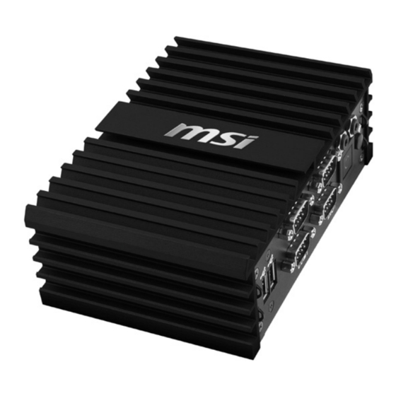
Overview Thank you for choosing the 9A59, an excellent industrial data machine from MSI. The MS-9A59 eliminates the noise and the risk of fan’s failure by wide heatsink as fanless solution. Fur- thermore, it supports VESA wall-mount interface for various scenarios like digital signage, kiosk, industrial... -
Page 10: Packing Contents
▍ Overview Packing Contents Power Adapter MS-9A59 Industrial Data Machine Power Cord Wall Mounting Brackets SATA Power & Signal Cable Driver/Utility Disc Phoenix Terminal Plugged ■ Please contact us immediately if any of the item is damaged or miss- ing. -
Page 11: System Overview
MS-9A59 System Overview Top View Front View USB 2�0 Port The USB (Universal Serial Bus) port is for attaching USB devices such as keyboard, mouse, or other USB-compatible devices. - Page 12 ▍ Overview RS232/422/485 Serial Port: COM1~COM2 The serial port is a 16550A high speed communications port that sends/ receives 16 bytes FIFOs. You can attach a serial mouse or other serial devices directly to the connector. Mode Signal TXD- TXD+ RS422 RXD- RXD+...
- Page 13 MS-9A59 DIO Port 1 This port is provided for the General-Purpose Input/Output (GPIO) pe- ripheral module. SIGNAL GPI0 GPO0 GPI1 GPO1 GPI2 GPO2 GPI3 GPO3 VCC5 Shell DIO Port 2 This port is provided for the General-Purpose Input/Output (GPIO) pe- ripheral module.
- Page 14 ▍ Overview Line-Out Jack This connector is provided for headphones or speakers. Power Button Press the power button to turn the system on or off. WLAN Antenna Connector (Optional) This connector allows you to connect an external antenna for wireless LAN.
- Page 15 MS-9A59 Gigabit LAN Jack The standard RJ-45 LAN jack is for connection to the Local Area Network (LAN). You can connect a network cable to it. USB 3�0 Port The USB 3.0 port is backward-compatible with USB 2.0 devices and supports data transfer rate up to 5 Gbit/s (SuperSpeed).
-
Page 16: System Specifications
▍ Overview System Specifications ■ Braswell N3160 QC-1.6GHz (2.24GHz for Burst) Memory ■ Single-channel DDR3L 1600MHz ■ Onboard 2GB ■ 1 Gigabit Fast Ethernet by Intel I211-ATcontroller Storage ■ 1 SATA 6Gb/s port ■ 1 mSATA slot (Supported up to 64GB) Audio ■... - Page 17 MS-9A59 Power ■ 36 watt switching power adapter ■ Input: 100~240Vac, 1.2A, 50~60Hz Supply ■ Output: 12Vdc, 3.0A ■ COM 1 (RS-232/422/485, 0V/5V/12V) ■ COM 2 (RS-232/422/485, 0V/5V/12V) Important - Before powering on the system, recheck the adapt- er to ensure safety D i m e n s i o n ■...
-
Page 18: Motherboard Jumper
▍ Overview Motherboard Jumper Important Avoid adjusting jumpers when the system is on; it will damage the motherboard. JINV1 JVDD1 JCMOS1 JATX1 JCOMP1 1-10... - Page 19 MS-9A59 Clear CMOS Jumper: JCMOS1 There is a CMOS RAM onboard that has a power supply from an external battery to keep the data of system configuration. With the CMOS RAM, the system can automatically boot OS every time it is turned on. If you want to clear the system configuration, set the jumper to clear data.
- Page 20 ▍ Overview LVDS Power Jumper: JVDD1 Use this jumper to specify the operation voltage of the LVDS interface flat panel. LVDS Inverter Power Jumper: JINV1 Use this jumper to specify the operation voltage of the interver interface flat panel. 1-12...
-
Page 21: Chapter 2 System Setup
Chapter 2 System Setup This chapter provides you with the information on hardware setup procedures. While doing the installation, be careful in holding the components and follow the installation procedures. For some components, if you install in the wrong orientation, the components will not work properly. -
Page 22: Installation Tools
▍ System Setup Installation Tools A Phillips (crosshead) screwdriver and a flathead screw- driver, can be used to do most of the installation. Choose one with a magnetic head would be better. Pliers, can be used as an auxiliary tool to connect some connectors or cables. -
Page 23: Removing The Cover
MS-9A59 Removing the Cover Place the system horizontally on a flat and steady surface. Locate and re- move the screws that secure the system cover. Slide the cover carefully sidewards and remove it from the system. -
Page 24: Installing Tpm Module
▍ System Setup Installing TPM Module Locate and remove the screws that secure the front cover. Move the front cover aside. Find the TPM module and stick its back with the double-sided tape. - Page 25 MS-9A59 Connect the TPM module. Fix the TPM module to the inner side of the chassis.
-
Page 26: Installing The Wlan Card (Optional)
▍ System Setup Installing the WLAN Card (Optional) Remove the wireless LAN antenna rubber plugs from the system. Find the antenna cable modules in the accessory box. Assemble the antenna cables to the system. - Page 27 MS-9A59 Locate the Mini PCIe slot. Remove the Mini PCIe card screw preinstalled on the motherboard. Insert the wireless LAN card into the slot at a 45-degree angle. Push the card gently downwards and fasten it with a screw.
-
Page 28: Installing The Msata Card
▍ System Setup Connect the wireless LAN cable. Follow the steps above to finish the other. Installing the mSATA Card Locate the Mini PCIe slot. Insert the mSATA card into the slot at a 45-degree angle. Push the card gently downwards and fasten it with a screw. -
Page 29: Installing The Lvds Cable (Optional)
MS-9A59 Installing the LVDS Cable (Optional) Remove the screw and LVDS brackets with a pliers. Connect the LVDS cable to LVDS connector on the motherboard. Please in- sert the LVDS cable with the right direction. Do not insert the cable with force. - Page 30 ▍ System Setup Install the LVDS cable. Fix the LVDS connector with two hexagonal screws attached. 2-10...
-
Page 31: Installing The 2.5" Ssd / Hhd
MS-9A59 Installing the 2.5” SSD / HHD Find the SATA cable module in the accessory box. Connect the power cable to the motherboard. Connect the signal cable to the motherboard. 2-11... - Page 32 ▍ System Setup Turn the cover upside down; and then, remove the sticker film to uncover the thermal paste. Loosen and remove the nuts. Put the 2.5” SSD / HDD on the cover with the screw wholes aligned and right direction. Cover Notch SATA connectors 2-12...
- Page 33 MS-9A59 Turn the cover upside down; and then, lock the screws. Connect the SATA cable module to the 2.5” SSD / HDD. Replace the cover and lock the screws. 2-13...
-
Page 34: Installing The Wlan Antenna (Optional)
▍ System Setup Installing the WLAN Antenna (Op- tional) Find the wireless LAN antennas in the accessory box. Turn clockwise to lock the antennas, anti-clockwise to unlock. Adjust the direction of the antennas to receive better wireless LAN signal. 2-14... -
Page 35: Installing The Wall Mount Brackets
MS-9A59 Installing the Wall Mount Brackets Place the system horizontally on a flat and steady surface. Locate and re- move the screws that secure the system cover. Find the wall mount bracket modules in the accessory box. 2-15... - Page 36 ▍ System Setup Insert the rubber pad in the whole. Insert the screw. Put the wall mount brackets on the system and lock the screws. 2-16...
-
Page 37: Wall Mount The Pc - Vesa Mound
MS-9A59 Wall Mount the PC - VESA Mound Align the VESA mount holes on the rear of the monitor and lock the VESA plate. Put the PC on the VEAS plate with the hooks aligned. Lock the thumb screw to fix the PC. -
Page 38: Wall Mount The Pc - Rail Mount
▍ System Setup Wall Mount the PC - Rail Mount Find the DIN rails in the accessory box. Put the DIN rails on the bracket with the hooks aligned. Lock the DIN rails with the screws attached. The PC is ready for rail mount. 2-18... -
Page 39: Chapter 3 Bios Setup
Chapter 3 BIOS Setup This chapter provides information on the BIOS Setup program and allows you to configure the system for optimum use. You may need to run the Setup program when: ■ An error message appears on the screen during the system booting up, and requests you to run SETUP. -
Page 40: Entering Setup
▍ BIOS Setup Entering Setup Power on the data machine and the system will start POST (Power On Self Test) process. When the message below appears on the screen, press <DEL> or <F2> key to enter Setup. Press <DEL> or <F2> to enter SETUP If the message disappears before you respond and you still wish to enter Set- up, restart the system by turning it OFF and On or pressing the RESET button. - Page 41 MS-9A59 Control Keys ← → Select Screen ↑ ↓ Select Item Enter Select Change Option General Help Previous Values Optimized Defaults Save & Reset Exit Getting Help After entering the Setup menu, the first menu you will see is the Main Menu.
-
Page 42: The Menu Bar
▍ BIOS Setup The Menu Bar ▶ Main Use this menu for basic system configurations, such as time, date, etc. ▶ Advanced Use this menu to set up the items of special enhanced features. ▶ Boot Use this menu to specify the priority of boot devices. ▶... -
Page 43: Main
MS-9A59 Main ▶ System Date This setting allows you to set the system date. The date format is <Day>, <Month> <Date> <Year>. ▶ System Time This setting allows you to set the system time. The time format is <Hour> <Min- ute>... -
Page 44: Advanced
▍ BIOS Setup Advanced ▶ Full Screen Logo Display This BIOS feature determines if the BIOS should hide the normal POST messag- es with the motherboard or system manufacturer’s full-screen logo. When it is enabled, the BIOS will display the full-screen logo during the boot-up sequence, hiding normal POST messages. - Page 45 MS-9A59 ▶ Super IO Configuration ▶ Serial Port 1/ 2 This setting enables/disables the specified serial port. ▶ Change Settings This setting is used to change the address & IRQ settings of the specified serial port. ▶ Mode Select Select an operation mode for the specified serial port.
- Page 46 ▍ BIOS Setup ▶ H/W Monitor These items display the current status of all monitored hardware devices/ components such as voltages, temperatures and all fans’ speeds. ▶ Thermal Shutdown This setting enables/disables the thermal shutdown function for system ther- mal protection.
- Page 47 MS-9A59 ▶ CPU Configuration ▶ Intel Virtualization Technology Virtualization enhanced by Intel Virtualization Technology will allow a plat- form to run multiple operating systems and applications in independent partitions. With virtualization, one computer system can function as multiple “Virtual” systems.
- Page 48 ▍ BIOS Setup ▶ PCI/PCIE Device Configuration ▶ Legacy USB Support Set to [Enabled] if you need to use any USB 1.1/2.0 device in the operating system that does not support or have any USB 1.1/2.0 driver installed, such as DOS and SCO Unix. ▶...
- Page 49 MS-9A59 ▶ GPIO Group Configuration ▶ GPO0 ~ GPO7 These settings control the operation mode of the specified GPIO. 3-11...
-
Page 50: Boot
▍ BIOS Setup Boot ▶ CSM Support This setting enables/disables the support for Compatibility Support Module, a part of the Intel Platform Innovation Framework for EFI providing the capability to support legacy BIOS interfaces. Important If the Operating System is going to boot in UEFI mode, disable CSM Support to speed up the boot process. - Page 51 MS-9A59 This setting allows users to set the priority of the specified devices. First press <Enter> to enter the sub-menu. Then you may use the arrow keys ( ↑↓ ) to select the desired device, then press <+>, <-> or <PageUp>, <PageDown> key to move it up/down in the priority list.
-
Page 52: Security
▍ BIOS Setup Security ▶ Administrator Password Administrator Password controls access to the BIOS Setup utility. ▶ User Password User Password controls access to the system at boot and to the BIOS Setup utility. 3-14... - Page 53 MS-9A59 ▶ Serial Port Console Redirection ▶ Console Redirection Console Redirection operates in host systems that do not have a moni- tor and keyboard attached. This setting enables/disables the operation of console redirection. When set to [Enabled], BIOS redirects and sends all contents that should be displayed on the screen to the serial COM port for display on the terminal screen.
- Page 54 ▍ BIOS Setup ▶ Bits per second, Data Bits, Parity, Stop Bits This setting specifies the transfer rate (bits per second, data bits, parity, stop bits) of Console Redirection. ▶ Flow Control Flow control is the process of managing the rate of data transmission between two nodes.
- Page 55 MS-9A59 ▶ Security Configuration ▶ TXE FW Version The setting shows the firmware information of the Intel Trusted Execution Engine(TXE). ▶ TXE HMRFPO The setting enables/disables TXE HMRFPO (Host ME Region Flash Pro- tection Override). ▶ TXE Firmware Update This setting enables/disables TXE FW update.
-
Page 56: Chipset
▍ BIOS Setup Chipset ▶ DVMT Pre-Allocated This setting defines the DVMT pre-allocated memory. Pre-allocated memory is the small amount of system memory made available at boot time by the system BIOS for video. Pre-allocated memory is also known as locked memory. This is because it is "locked"... -
Page 57: Power
MS-9A59 Power ▶ Restore AC Power Loss This setting specifies whether your system will reboot after a power failure or interrupt occurs. Available settings are: [Power Off] Leaves the computer in the power off state. [Power On] Leaves the computer in the power on state. - Page 58 ▍ BIOS Setup ** Advanced Resume Events Control ** ▶ PCIE PME This field specifies whether the system will be awakened from power saving modes when activity or input signal of onboard PCIE PME is detected. ▶ USB from S3/S4 The item allows the activity of the USB device to wake up the system from S3/ S4 sleep state.
-
Page 59: Save & Exit
MS-9A59 Save & Exit ▶ Save Changes and Reset Save changes to CMOS and reset the system. ▶ Discard Changes and Exit Abandon all changes and exit the Setup Utility. ▶ Discard Changes Abandon all changes. ▶ Load Optimal Defaults Use this menu to load the default values set by the motherboard manufacturer specifically for optimal performance of the motherboard. - Page 60 ▍ BIOS Setup 3-22...
-
Page 61: Appendix Wdt & Gpio
Appendix WDT & GPIO This appendix provides the sample codes of WDT (Watch Dog Timer) and GPIO (General Purpose Input/ Output). - Page 62 ▍ WDT & GPIO WDT Sample Code SIO_INDEX_Port equ 04Eh SIO_DATA_Port equ 04Fh SIO_UnLock_Value equ 087h SIO_Lock_Value equ 0AAh WatchDog_LDN equ 007h WDT_UNIT equ 60h ;60h=second, 68h=minute, 40h=Disabled Watchdog timer WDT_Timer equ 30 ;ex. 30 seconds Sample code: ;Enable config mode dx, SIO_INDEX_Port al, SIO_UnLock_Value dx, al...
- Page 63 MS-9A59 GPIO Sample Code GPI 0 ~ GPI 7 GPI 0 GPI 1 GPI 2 GPI 3 GPI 4 GPI 5 GPI 6 GPI 7 IO Address SIO GPIO Register Sample code GPO 0 ~ GPO 7 GPO 0...
- Page 64 ▍ WDT & GPIO dx, SIO_INDEX_Port al, SIO_GPIO_Status dx, al dx, SIO_DATA_Port al, dx ;al bit0 = GPI 0 status ; Exit SIO dx, SIO_INDEX_Port al, SIO_Lock_Value dx, al #2 : Set GPO 0 to high ; Enable config mode dx, SIO_INDEX_Port al, SIO_UnLock_Value dx, al...
Need help?
Do you have a question about the MS-9A59 and is the answer not in the manual?
Questions and answers