Page 1
PT-RZ7 PT-RZ6 
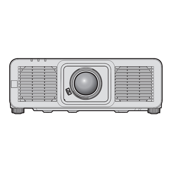
The projection lens is sold separately. Thank you for purchasing this Panasonic product. ■ This manual is common to all the models regardless of suffixes of the Model No. z for USA, Canada, Mexico, Brazil LW: White model...
Contents Contents Read this first! Installing the Function Board Before installing or removing the Function Board Chapter 1 Preparation For Intel SDM-S specification Function Board ® Installing the Function Board Precautions for use Removing the Function Board Intended use of the product Installing the SFP module Installation and handling of the laser product Removing the SFP module...
Page 3
Contents Chapter 4 Settings [DISPLAY OPTION] menu [COLOR MATCHING] Menu navigation [COLOR CORRECTION] Navigating through the menu [SCREEN SETTING] Main menu [BACKUP INPUT SETTING] Sub-menu [HDMI IN] [PICTURE] menu [DIGITAL LINK IN] [PICTURE MODE] [SLOT IN] [CONTRAST] [ON-SCREEN DISPLAY] [BRIGHTNESS] [MENU MODE] [COLOR] [BACK COLOR]...
Page 4
Contents [SIGNAL LIST] menu Updating the firmware Registering new signals Updating the firmware via LAN Renaming the registered signal Updating the firmware using the USB memory Deleting the registered signal Expanding signal lock-in range Chapter 6 Maintenance Protecting the registered signal Sub memory Light source/temperature indicators [SECURITY] menu...
Read this first! Read this first! WARNING: THIS APPARATUS MUST BE EARTHED. WARNING: T o prevent damage which may result in fire or shock hazard, do not expose this appliance to rain or moisture. T his device is not intended for use in the direct field of view at visual display workplaces. To avoid incommoding reflexions at visual display workplaces this device must not be placed in the direct field of view. T he equipment is not intended for used at a video workstation in compliance BildscharbV. The sound pressure level at the operator position is equal or less than 70 dB (A) according to ISO 7779. WARNING: 1.
Page 6
Read this first! WARNING: R ISK OF ELECTRIC SHOCK. DON’T OPEN Indicated on the projector The lightning flash with arrowhead symbol, within an equilateral triangle, is intended to alert the user to the presence of uninsulated “dangerous voltage” within the product’s enclosure that may be of sufficient magnitude to constitute a risk of electric shock to persons. The exclamation point within an equilateral triangle is intended to alert the user to the presence of important operating and maintenance (servicing) instructions in the literature accompanying the product. WARNING: Do not look at the light emitted from the lens while the projector is being used. As with any bright source, do not stare into the direct beam, RG2 IEC 62471-5:2015. Indicated on the projector (for USA and Canada) WARNING: M OUNT ABOVE THE HEADS OF CHILDREN. The use of a ceiling mount is recommended with this projector to place it above the eyes of children.
Page 7
Read this first! (for other countries or regions) This projector is the Class 1 laser product that complies with IEC 60825-1:2014. CAUTION: Use of controls or adjustments or performance of procedures other than those specified herein may result in hazardous radiation exposure. CAUTION (North/Middle/South America, Taiwan) This equipment is equipped with a three-pin grounding-type power plug. Do not remove the grounding pin on the power plug. This plug will only fit a grounding-type power outlet. This is a safety feature. If you are unable to insert the plug into the outlet, contact an electrician. Do not defeat the purpose of the grounding plug. Do not remove WARNING (USA and Canada) f Not for use in a computer room as defined in the Standard for the Protection of Electronic Computer/Data Processing Equipment, ANSI/NFPA 75.
Page 8
The battery is hazardous, KEEP new and used batteries OUT OF REACH of CHILDREN f Seek immediate medical attention if a battery is suspected to be swallowed or inserted inside any part of the body. FCC NOTICE (USA) Supplier’s Declaration of Conformity Model Number: PT-RQ7LB / PT-RQ6LB / PT-RZ7LB / PT-RZ7LW / PT-RZ6LB / PT-RZ6LW Trade Name: Panasonic Responsible Party: Panasonic Corporation of North America Address: Two Riverfront Plaza, Newark, NJ 07102-5490 General Contact: http://www.panasonic.com/support Projector Contact: 855-772-8324 or projectorsupport@us.panasonic.com This device complies with Part 15 of the FCC Rules. Operation is subject to the following two conditions: (1) This device may not cause harmful interference, and (2) this device must accept any interference received, including interference that may cause undesired operation.
Page 9
Read this first! IMPORTANT: THE MOLDED PLUG FOR YOUR SAFETY, PLEASE READ THE FOLLOWING TEXT CAREFULLY. This appliance is supplied with a molded three pin mains plug for your safety and convenience. A 13 amp fuse is fitted in this plug. Should the fuse need to be replaced, please ensure that the replacement fuse has a rating of 13 amps and that it is approved by ASTA or BSI to BS1362. Check for the ASTA mark or the BSI mark on the body of the fuse. If the plug contains a removable fuse cover, you must ensure that it is refitted when the fuse is replaced. If you lose the fuse cover, the plug must not be used until a replacement cover is obtained. A replacement fuse cover can be purchased from an Authorized Service Center. If the fitted molded plug is unsuitable for the mains socket in your home, then the fuse should be removed and the plug cut off and disposed of safely.
Page 10
Read this first! r Hazard distance (IEC 62471-5:2015) The distance from the projection lens surface, at which the emission reaches the Accessible Emission Limit (AEL) of risk group 2, is known as the hazard distance (HD) or safety distance. The area where the emission exceeds the Accessible Emission Limit of risk group 2 is called the hazard zone (HZ). Within the hazard zone, never look into the light projected from the projector. The eyes may be damaged by direct irradiation even if you look at the light just for a moment. If you are outside the hazard zone, it is considered to be safe in all circumstances except deliberately staring into the light projected from the projector. Except ET-DLE035 r Risk group The combination of the projector and the projection lens is categorized as risk group 2 when the hazard distance is 1 m (39-3/8") or less. It is categorized as risk group 3 when the hazard distance exceeds 1 m (39-3/8 ), and it " will be for professional use instead of consumer use. In case of risk group 3, there is a possibility of damaging the eyes by direct irradiation when looking into the projection light from inside the hazard zone even for a moment. In the case of risk group 2, safe use without damaging the eyes is possible in all circumstances except deliberately staring into the light projected from the projector. The combination of the projector and the projection lens which the hazard distance exceeds 1 m (39-3/8") and is categorized as risk group 3 is as follows. Projection lens Model No. Risk group ET-DLE350 Risk group 3...
Page 11
(Unit: m) Projection lens Model No. 0.23 0.23 0.25 0.25 ET-DLE350 0.18 0.18 0.20 0.20 ET-DLE450 *1 HD: Hazard Distance *2 The values of D1 to D4 will change in accordance with the lens shift amount. Each value in the table is the maximum value. Note f The value in the table is based on IEC 62471-5:2015. f Projection lens compatible with the projector may be added or changed without prior notice. For the latest information, visit the following website. https://docs.connect.panasonic.com/projector Attention f If the light projected from the projector directly enters the eyes while you are inside the hazard zone, the retinas may be damaged. Do not enter within the hazard zone during use. Alternatively, install the projector in a location where the projected light will not directly enter the eyes. ENGLISH - 11...
Page 12
Read this first! WARNING: r POWER The wall outlet or the circuit breaker shall be installed near the equipment and shall be easily accessible when problems occur. If the following problems occur, cut off the power supply immediately. Continued use of the projector in these conditions will result in fire or electric shock, or will cause visual impairment. f If foreign objects or water get inside the projector, cut off the power supply.
Page 13
Do not place containers of liquid or metal objects near the projector. f If liquid enters inside of the projector, consult your dealer. f Particular attention must be paid to children. Use the ceiling mount bracket specified by Panasonic Connect Co., Ltd. Using the ceiling mount bracket other than the specified one will result in falling accidents. f Attach the supplied safety cable to the ceiling mount bracket to prevent the projector from falling down. Installation work such as mounting the projector on the ceiling should only be carried out by a qualified technician.
Page 14
Read this first! CAUTION: r POWER When disconnecting the power cord, be sure to hold the power plug and power connector. If the power cord itself is pulled, the lead will become damaged, and fire, short-circuits or serious electric shocks will result. When not using the projector for an extended period of time, disconnect the power plug from the wall outlet.
Page 15
Read this first! CAUTION: r ACCESSORIES When not using the projector for an extended period of time, remove the batteries from the remote control. Failure to observe this will cause the batteries to leak, overheat, catch fire or explode, which may result in fire or contamination of surrounding area. r MAINTENANCE Ask your dealer about cleaning inside the projector every 20 000 hours of usage as an estimated duration.
Page 16
Read this first! Brazil Only Brasil Apenas r Manuseio de baterias usadas BRASIL Após o uso, as pilhas e/ou baterias deverão ser entregues ao estabelecimento comercial ou rede de assistência técnica autorizada. Cobrir os terminais positivo (+) e negativo (-) com uma fita isolante adesiva, antes de depositar numa caixa destinada para o recolhimento. O contato entre partes metálicas pode causar vazamentos, gerar calor, romper a blindagem e produzir fogo. (Fig. 1) Fig. 1 Fita Isolante Como isolar os terminais Fita Isolante Não desmonte, não remova o invólucro, nem amasse a bateria. O gás liberado pela bateria pode irritar a garganta, danificar o lacre do invólucro ou o vazamento provocar calor, ruptura da blindagem e produzir fogo devido ao curto circuito dos terminais. Não incinere nem aqueça as baterias, elas não podem ficar expostas a temperaturas superiores a 100 °C (212 °F). O gás liberado pela bateria pode irritar a garganta, danificar o lacre do invólucro ou o vazamento provocar calor, ruptura da blindagem e produzir fogo devido ao curto circuito dos terminais provocado internamente. Evite o contato com o liquido que vazar das baterias. Caso isto ocorra, lave bem a parte afetada com bastante água. Caso haja irritação, consulte um médico. r Remoção das baterias 1.
Page 17
AEEE Yönetmeliğine Uygundur For India Only Information on hazardous constituents as specified in the E-Waste (Management) Rules in electrical and electronic equipment. Declaration of Conformity with the requirements of the E-Waste (Management) Rules limits with respect to Lead, Mercury, Cadmium, Hexavalent chromium, Polybrominated biphenyls,Polybrominated diphenyl ethers. The content of hazardous substance with the exemption of the applications listed in the E-Waste (Management) Rules: 1. Lead (Pb) – not over 0.1% by weight. 2. Cadmium (Cd) – not over 0.01% by weight. 3. Mercury (Hg) – not over 0.1% by weight. 4. Hexavalent chromium (Cr6+) – not over 0.1% by weight. 5. Polybrominated biphenyls (PBBs) – not over 0.1% by weight. 6. Polybrominated diphenyl ethers (PBDEs) – not over 0.1% by weight. For the purpose of recycling to facilitate effective utilization of resources, please return this product to a nearby authorized collection center, registered dismantler of recycler, or Panasonic service center when disposing of this product. Customer care number ( Toll free ) : 080-6984-1333 Please see the Panasonic website for further information on collection centers, etc. or call the customer care toll-free number. https://www.panasonic.com/in/corporate/e-waste-management.html Do's & Don'ts Do's Don'ts All electrical and electronic products are required The product should not be opened by the user himself to be handed over only to the Authorized recycler. / herself, but only by authorized service personnel. The product should be handed over only to The product is not meant for re-sale to any authorized recycler for disposal.
Page 18
For details, refer to “Using the web control function” (x page 229). At least three (3) years from delivery of this product, Panasonic Connect Co., Ltd. will give to any third party who contacts us at the contact information provided below, for a charge no more than our cost of physically performing source code distribution, a complete machine-readable copy of the corresponding source code covered under GPL V2.0, LGPL V2.1 or the other licenses with the obligation to do so, as well as the respective copyright notice...
Page 19
rTerm f In this manual, the “Wireless/wired remote control unit” accessory is referred to as “Remote control”. ENGLISH - 19...
Page 20
Features of the Projector Quick Steps For details, refer to the corresponding pages. 1. Set up the projector. High image quality and versatile image expression (x page 40) ▶ With a new-generation laser light source 2. Attach the projection lens. and a unique optical system, high luminance is achieved while maintaining (x page 64)
The variance application to the U.S. Food and Drug Administration (FDA variance application) will be performed by Panasonic Connect Co., Ltd. The person responsible of the device or usage shall store the original or a copy of the FDA variance approval letter received from Panasonic Connect Co., Ltd.
Page 23
Chapter 1 Preparation — Precautions for use f Near the exhaust of an air conditioner: Depending on the conditions of use, the screen may fluctuate in rare cases due to the heated air from the exhaust vent or the hot or cooled air from the air conditioner. Make sure that the exhaust from the projector or other equipment, or the air from the air conditioner does not blow toward the front of the projector.
Chapter 1 Preparation — Precautions for use rProjection in all 360° direction is possible. 360° 360° 360° 360° tilted 360° vertically 360° horizontally (combination of vertical and horizontal) Cautions when setting up the projector f Use the adjustable feet only for the floor standing installation and for adjusting the angle. Using them for other purposes may damage the projector.
Make your password difficult to guess as much as possible. f Change your password periodically. f Panasonic Connect Co., Ltd. or its affiliate companies will never ask for your password directly. Do not divulge your password in case you receive such inquiries.
Depending on the specifications of the wireless LAN, a malicious third party may be able to break security settings by special means. Panasonic Connect Co., Ltd. asks customers to thoroughly understand the risk of using this product without making security settings, and recommends that the customers make security settings at their own discretion and responsibility.
(PT-RQ7 / PT-RQ6 only) “QUAD PIXEL DRIVE” is a technology unique to Panasonic Connect Co., Ltd. that will enhance the resolution of the projected image with the signal processing for the high resolution of up to 3 840 x 2 160 dots and quadrupling the resolution by shifting the image pixels in horizontal and vertical directions.
Chapter 1 Preparation — Precautions for use f Geometric & Setup Management Software (Geometry Manager Pro) This application software performs detailed corrections and adjustments such as the geometric adjustment which cannot be covered by the projector settings in real-time. Also, the geometric adjustment and edge blending to match the shape of the screen, and the adjustment of color and luminance can be automatically performed within simple steps by using a camera.
Chapter 1 Preparation — Precautions for use Accessories Make sure that the following accessories are provided with your projector. Numbers enclosed in < > show the number of accessories. Wireless/wired remote control unit <1> For India (N2QAYA000256) (K2CZ3YY00104) <1> 200 V - 240 V For Taiwan (K2CG3YY00145) <1>...
The optional accessories compatible with the projector may be added or changed without prior notice. The optional accessories described in this document are as of September 2024. For the latest information, visit the following website. https://docs.connect.panasonic.com/projector 30 - ENGLISH...
Chapter 1 Preparation — About your projector About your projector Remote control Front Bottom <STANDBY> button <FUNCTION> button Sets the projector to the state where the projector is turned Assigns a frequently used operation as a shortcut button. off (standby mode) when the <MAIN POWER> switch on the (x page 103) When the <FUNCTION>...
Page 32
Chapter 1 Preparation — About your projector Attention f Do not drop the remote control. f Avoid contact with liquids or moisture. f Do not attempt to modify or disassemble the remote control. f Observe the following instructions that are indicated on the caution label at the back of the remote control: g Do not use old battery with new one.
Chapter 1 Preparation — About your projector Projector body Front Side 2 3 4 Rear Bottom Projection direction Remote control signal receiver (front) Control panel (x page 34) Power indicator <ON (G)/STANDBY (R)> 10 Security slot Indicates the status of the power. This security slot is compatible with the Kensington security cables.
Page 34
Chapter 1 Preparation — About your projector r Control panel <POWER ON> button asqw buttons Sets the projector to projection mode when the <MAIN Used to select items in the menu screen, change settings, and POWER> switch on the projector is set to <ON> and the power adjust levels.
Page 35
Chapter 1 Preparation — About your projector r Connecting terminals <SERIAL IN> terminal <HDMI IN 1> terminal/<HDMI IN 2> terminal This is the RS-232C compatible terminal to externally control This is a terminal to input HDMI signal. the projector by connecting a computer. <DIGITAL LINK/LAN>...
Confirmation of operation for SFP module from other manufacturer has been performed with the items set independently by Panasonic Connect Co., Ltd., and not all the operations are warranted. For operation or performance problems caused by the SFP module, contact the respective manufacturers.
Page 37
Chapter 1 Preparation — About your projector rWhen the SFP modules are installed This is an example when the SFP module for receiving (LC connector) is installed in the SFP port 1, and the SFP module for sending and receiving (LC connector) is installed in the SFP port 2. SDI OPT 1 IN 2 IN...
Chapter 1 Preparation — Preparing the remote control Preparing the remote control Inserting and removing the batteries (ii) Fig. 1 Fig. 2 Open the cover. (Fig. 1) Insert the batteries and close the cover (insert the m side first). (Fig. 2) f When removing the batteries, perform the steps in reverse order.
Chapter 2 Getting Started — Setting up Setting up Usable outlet This projector supports AC 100 V to AC 240 V as the power supply. A grounded outlet supporting 15 A is required with either voltage. The shape of the usable outlet differs depending on the power supply. Following illustrations are examples. 2P/3W 15 A 250 V 2P/3W 16 A 250 V 2P/3W 16 A 250 V...
Chapter 2 Getting Started — Setting up Portrait setting and projecting forward Portrait setting and projecting from the rear (Using the translucent screen) Menu item Setting value Menu item Setting value [FRONT/REAR] [FRONT] [FRONT/REAR] [REAR] Set in accordance with the image Set in accordance with the image [FLOOR/CEILING] [FLOOR/CEILING]...
Chapter 2 Getting Started — Setting up Projected image and throw distance Install the projector referring to the projected image size, projection distance, etc. The projection relation between the screen and the projector differs from that of other lenses, when the Fixed- focus Lens (Model No.: ET-DLE035) is used.
Page 43
Chapter 2 Getting Started — Setting up r Fixed-focus Lens (Model No.: ET-DLE035) Projected image Screen Screen Note f This illustration is prepared on the assumption that the projected image size and position have been aligned to fit full in the screen. Projected image height Projected image width Projected image size...
Page 44
Chapter 2 Getting Started — Setting up [GEOMETRY] projection range [VERTICAL KEYSTONE] (viewed from the side) [HORIZONTAL KEYSTONE] (viewed from above) Screen Screen Vertical arc correction (viewed from the side) Horizontal arc correction (viewed from above) Projection distance Projection distance Arc radius Arc radius Screen Screen...
Page 45
Chapter 2 Getting Started — Setting up Note f When [GEOMETRY] is used, the focus of the entire screen may be lost as correction increases. f Make the curved screen a circular arc shape with one part of a perfect circle removed. f Adjustment range of the [GEOMETRY] items may not match the listed projection range depending on the projection lens.
Page 46
Chapter 2 Getting Started — Setting up Lens type Zoom Lens ET-DLE170 / ET-DLE150 / ET-DLE085 / ET-DLE020G / Projection lens Model No. ET-DLE250 / ET-DLE060 ET-DLE105 ET-DLE020 ET-DLE350 / ET-DLE450 Projected image size Height position (H) Height Width Diagonal (SD) (SH) (SW) 1.27 (50")
Page 47
Chapter 2 Getting Started — Setting up r When the image aspect ratio is 16:10 (Unit: m) Lens type Zoom Lens ET-DLE020G / Projection lens Model No. ET-DLE170 ET-DLE060 ET-DLE085 ET-DLE105 ET-DLE020 Throw ratio 1.90-2.67:1 0.310-0.331:1 0.666-0.888:1 0.867-1.08:1 1.08-1.47:1 Projected image size Projection distance (L) Height Width...
Page 48
Chapter 2 Getting Started — Setting up Lens type Zoom Lens ET-DLE170 / ET-DLE150 / ET-DLE085 / ET-DLE020G / Projection lens Model No. ET-DLE250 / ET-DLE060 ET-DLE105 ET-DLE020 ET-DLE350 / ET-DLE450 Projected image size Height position (H) Height Width Diagonal (SD) (SH) (SW) 1.27 (50")
Page 49
Chapter 2 Getting Started — Setting up r When the image aspect ratio is 4:3 (Unit: m) Lens type Zoom Lens ET-DLE020G / Projection lens Model No. ET-DLE170 ET-DLE060 ET-DLE085 ET-DLE105 ET-DLE020 Throw ratio 2.29-3.21:1 0.373-0.399:1 0.804-1.07:1 1.04-1.30:1 1.30-1.76:1 Projected image size Projection distance (L) Height Width...
Page 50
Chapter 2 Getting Started — Setting up Lens type Zoom Lens ET-DLE170/ ET-DLE150/ ET-DLE085/ ET-DLE020G / Projection lens Model No. ET-DLE250/ ET-DLE060 ET-DLE105 ET-DLE020 ET-DLE350/ ET-DLE450 Projected image size Height position (H) Height Width Diagonal (SD) (SH) (SW) 1.27 (50") 0.762 1.016 -0.12 - 0.52 -0.08 - 0.52...
Page 51
Chapter 2 Getting Started — Setting up r When the image aspect ratio is 21:9 (Unit: m) Lens type Zoom Lens ET-DLE020G / Projection lens Model No. ET-DLE170 ET-DLE060 ET-DLE085 ET-DLE105 ET-DLE020 Throw ratio 1.71-2.40:1 0.279-0.298:1 0.599-0.799:1 0.780-0.973:1 0.975-1.32:1 Projected image size Projection distance (L) Height Width...
Page 52
Chapter 2 Getting Started — Setting up Lens type Zoom Lens ET-DLE170/ ET-DLE150/ ET-DLE085/ ET-DLE020G / Projection lens Model No. ET-DLE250/ ET-DLE060 ET-DLE105 ET-DLE020 ET-DLE350/ ET-DLE450 Projected image size Height position (H) Height Width Diagonal (SD) (SH) (SW) 1.27 (50") 0.494 1.170 -0.19 - 0.37 -0.15 - 0.37...
Page 53
Chapter 2 Getting Started — Setting up For PT-RZ7 / PT-RZ6 r When the image aspect ratio is 16:10 (Unit: m) Lens type Zoom Lens ET-DLE020G / Projection lens Model No. ET-DLE170 ET-DLE060 ET-DLE085 ET-DLE105 ET-DLE020 Throw ratio 1.71-2.41:1 0.280-0.299:1 0.600-0.801:1 0.782-0.977:1 0.978-1.32:1 Projected image size...
Page 54
Chapter 2 Getting Started — Setting up Lens type Zoom Lens ET-DLE170/ ET-DLE150/ ET-DLE085/ ET-DLE020G / Projection lens Model No. ET-DLE250/ ET-DLE060 ET-DLE105 ET-DLE020 ET-DLE350/ ET-DLE450 Projected image size Height position (H) Height Width Diagonal (SD) (SH) (SW) 1.27 (50") 0.673 1.077 -0.07 - 0.44 -0.03 - 0.44...
Page 55
Chapter 2 Getting Started — Setting up r When the image aspect ratio is 16:9 (Unit: m) Lens type Zoom Lens ET-DLE020G / Projection lens Model No. ET-DLE170 ET-DLE060 ET-DLE085 ET-DLE105 ET-DLE020 Throw ratio 1.72-2.41:1 0.280-0.299:1 0.600-0.802:1 0.783-0.977:1 0.979-1.32:1 Projected image size Projection distance (L) Height Width...
Page 56
Chapter 2 Getting Started — Setting up Lens type Zoom Lens ET-DLE170/ ET-DLE150/ ET-DLE085/ ET-DLE020G / Projection lens Model No. ET-DLE250/ ET-DLE060 ET-DLE105 ET-DLE020 ET-DLE350/ ET-DLE450 Projected image size Height position (H) Height Width Diagonal (SD) (SH) (SW) 1.27 (50") 0.623 1.107 -0.10 - 0.42 -0.07 - 0.42...
Page 57
Chapter 2 Getting Started — Setting up r When the image aspect ratio is 4:3 (Unit: m) Lens type Zoom Lens ET-DLE020G / Projection lens Model No. ET-DLE170 ET-DLE060 ET-DLE085 ET-DLE105 ET-DLE020 Throw ratio 2.06-2.90:1 0.337-0.361:1 0.724-0.965:1 0.943-1.18:1 1.18-1.59:1 Projected image size Projection distance (L) Height Width...
Page 58
Chapter 2 Getting Started — Setting up Lens type Zoom Lens ET-DLE170/ ET-DLE150/ ET-DLE085/ ET-DLE020G / Projection lens Model No. ET-DLE250/ ET-DLE060 ET-DLE105 ET-DLE020 ET-DLE350/ ET-DLE450 Projected image size Height position (H) Height Width Diagonal (SD) (SH) (SW) 1.27 (50") 0.762 1.016 -0.08 - 0.50 -0.04 - 0.50...
Page 59
Chapter 2 Getting Started — Setting up r When the image aspect ratio is 21:9 (Unit: m) Lens type Zoom Lens ET-DLE020G / Projection lens Model No. ET-DLE170 ET-DLE060 ET-DLE085 ET-DLE105 ET-DLE020 Throw ratio 1.72-2.42:1 0.280-0.300:1 0.602-0.803:1 0.784-0.979:1 0.980-1.33:1 Projected image size Projection distance (L) Height Width...
Page 60
Chapter 2 Getting Started — Setting up Lens type Zoom Lens ET-DLE170/ ET-DLE150/ ET-DLE085/ ET-DLE020G / Projection lens Model No. ET-DLE250/ ET-DLE060 ET-DLE105 ET-DLE020 ET-DLE350/ ET-DLE450 Projected image size Height position (H) Height Width Diagonal (SD) (SH) (SW) 1.27 (50") 0.494 1.170 -0.19 - 0.36 -0.16 - 0.36...
Page 61
Chapter 2 Getting Started — Setting up Formula for calculating the projection distance per projection lens To use a projected image size not listed in this manual, check the projected image size SD (m) and use the respective formula to calculate projection distance. The unit of all the formulae is m.
Page 62
Chapter 2 Getting Started — Setting up r Fixed-focus Lens (Model No.: ET-DLE035) Projection distance (L1) Distance (A1) formula from Projection lens Model No. Throw ratio Aspect ratio formula the projector to the screen 0.378:1 16:9 =0.3278 x SD + 0.004 =0.2295 x SD - 0.073 0.420:1 16:10...
Chapter 2 Getting Started — Setting up r Fixed-focus Lens (Model No.: ET-DLE035) Projection distance (L1) Distance (A1) formula from Projection lens Model No. Throw ratio Aspect ratio formula the projector to the screen 0.380:1 16:10 =0.3206 x SD + 0.004 =0.1993 x SD - 0.073 0.380:1 16:9...
Do not touch the surface of the projection lens with your bare hands. f Panasonic Connect Co., Ltd. takes no responsibility for any damage or malfunction of the product resulting from the use of projection lenses which are not manufactured by Panasonic Connect Co., Ltd.. Be sure to use the specified projection lenses.
Chapter 2 Getting Started — Attaching/removing the projection lens Attention f After attaching the projection lens, turn on the projector and confirm the [LENS TYPE] setting. Change the setting if the type does not match the projection lens attached to the projector. (x page 97) Removing the projection lens Remove the projection lens using the following procedure.
Confirmation of operation for the devices of other manufacturers has been performed with the items set independently by Panasonic Connect Co., Ltd., and not all the operations are warranted. For operation or performance problems caused by the devices of other manufacturers, contact the respective manufacturers.
Chapter 2 Getting Started — Installing the Function Board For Intel SDM-S specification Function Board ® Attach the supplied SLOT adapter in advance when installing a narrow width Intel SDM Small (Intel SDM-S) ® ® specification Function Board. SLOT adapter Guide Function Board screw Fig.
Chapter 2 Getting Started — Installing the Function Board Installing the Function Board Screws (two locations) Guide rail Screws (two locations) Slot cover Fig. 1 Fig. 2 Fig. 3 Remove the slot cover. (Fig. 1) f Remove the two screws fixing the slot cover by rotating counterclockwise with a Phillips screwdriver. The removed screws are used to fix the Function Board.
Chapter 2 Getting Started — Installing the Function Board Installing the SFP module The following is an example of installation procedure for the SFP module. Please also check the operating instructions and setup guide of the SFP module. SFP modules SFP ports Circuit boards Fig.
Chapter 2 Getting Started — Installing the Function Board Removing the SFP module The following is an example of removal procedure for the SFP module. Please also check the operating instructions and setup guide of the SFP module. Lever Lever Latch SFP modules Fig.
Chapter 2 Getting Started — Connecting Connecting Before connecting f Before connecting, carefully read the operating instructions for the external device to be connected. f Turn off the power of all devices before connecting cables. f Connect cables taking care of the following descriptions. Failure to do so may result in malfunctions. g When connecting a cable to a device connected to the projector or the projector itself, touch any nearby metallic objects to eliminate static electricity from your body before performing work.
Chapter 2 Getting Started — Connecting Connecting example: AV equipment For <HDMI IN 1> / <HDMI IN 2> terminals Blu-ray disc player 蓝光光盘播放机 Note f When HDMI signal is input, switching of the setting in the [DISPLAY OPTION] menu → [HDMI IN] → [HDMI1] / [HDMI2] → [EDID SELECT] may be required depending on the connected external device or the input signal.
Page 73
Chapter 2 Getting Started — Connecting f Directly connect the projector with the external device that will output the signal without going through a distributor, etc., when inputting quad link signals. A phase difference is generated between the signals of Link 1, Link 2, Link 3, and Link 4, and the image may not be projected correctly.
Chapter 2 Getting Started — Connecting Connecting example: Computers Control computer Control computer Computer Attention f When connecting the projector to a computer or an external device, use the power cord supplied with each device and commercially available shielded cables. Note f When HDMI signal is input, switching of the setting in the [DISPLAY OPTION] menu →...
Chapter 2 Getting Started — Connecting Connecting example using DIGITAL LINK Twisted-pair-cable transmitters based on the communication standard HDBaseT such as the optional DIGITAL LINK output supported device (Model No.: ET-YFB100G, ET-YFB200G) use the twisted pair cable to transmit input images, Ethernet, and serial control signal, and the projector can input such digital signal to the <DIGITAL LINK/LAN>...
If these distances are exceeded, image may be disrupted or a malfunction may occur in LAN communication. Please note that Panasonic Connect Co., Ltd. does not support the use of the projector outside the maximum transmission distance.
Page 77
Chapter 2 Getting Started — Connecting Connecting example Connect all target projectors to the same network when using the contrast synchronization function/shutter synchronization function. Connecting terminals of the synchronization source Connecting terminals of the projector to synchronize LAN cable (straight) LAN cable (straight) Switching hub LAN cable (straight) LAN cable (straight)
Chapter 3 Basic Operations — Switching on/off the projector Switching on/off the projector Connecting the power cord Make sure that the supplied power cord is securely fixed to the <AC IN> terminal of the projector to prevent it from being removed easily. Confirm that the <MAIN POWER>...
Chapter 3 Basic Operations — Switching on/off the projector Raise the power cord holder fixing the power cord upward. (Fig. 1) f Fix the power cord holder by snapping into the projector. While holding the power cord connector, pull out the power cord from the <AC IN> terminal of the projector.
Chapter 3 Basic Operations — Switching on/off the projector f The power indicator <ON (G)/STANDBY (R)> will blink green slowly while the shutter function is in use (shutter: closed), or while the function of the [PROJECTOR SETUP] menu → [NO SIGNAL SETTING] → [NO SIGNAL LIGHTS-OUT] (x page 178) is operating and the light source is turned off.
Chapter 3 Basic Operations — Switching on/off the projector When the initial setting screen is displayed When the projector is switched on for the first time after purchase, or when the [PROJECTOR SETUP] menu → [INITIALIZE] → [FACTORY RESET] is executed, the focus adjustment screen is displayed after the projection starts, followed by the [INITIAL SETTING] screen and the [ADMINISTRATOR ACCOUNT] screen.
Page 83
Chapter 3 Basic Operations — Switching on/off the projector Initial setting (operation setting) Set the items for the operating method depending on the projector’s application and duration of usage. After completed the initial setting, you can change the settings of each item from the [PROJECTOR SETUP] menu →...
Page 84
Chapter 3 Basic Operations — Switching on/off the projector Relationship between brightness and runtime The projector can be operated with arbitrary brightness and runtime by setting [LIGHT OUTPUT] to desired setting. The relationship between the [LIGHT OUTPUT] setting, brightness, and the estimated runtime is as follows. Make the initial setting (operation setting) depending on the desired brightness of the projected image and runtime.
Page 85
Chapter 3 Basic Operations — Switching on/off the projector Initial setting (installation setting) Set [FRONT/REAR] and [FLOOR/CEILING] in [PROJECTION METHOD] depending on the installation mode. Refer to “Installation mode” (x page 40) for details. After completed the initial setting, you can change the setting from the [PROJECTOR SETUP] menu → [PROJECTION METHOD].
Page 86
Chapter 3 Basic Operations — Switching on/off the projector Initial setting (screen setting) Set the screen format (aspect ratio) and display position of the image. After completed the initial setting, you can change the settings of each item from the [DISPLAY OPTION] menu → [SCREEN SETTING].
Page 87
Chapter 3 Basic Operations — Switching on/off the projector Initial setting (EDID setting) (PT-RQ7 / PT-RQ6 only) Set the main input resolution of the image signal.The setting is reflected as the initial setting of [EDID SELECT] for <HDMI IN 1> terminal / <HDMI IN 2> terminal / <DIGITAL LINK/LAN> terminal. After completed the initial setting, you can change the setting from the following menu item.
Chapter 3 Basic Operations — Switching on/off the projector Initial setting (date and time) Set the local date and time. After completed the initial setting, you can change the setting from the [PROJECTOR SETUP] menu → [DATE AND TIME]. To set the date and time automatically, refer to “Setting the date and time automatically” (x page 180). Press as to select an item.
Page 89
Chapter 3 Basic Operations — Switching on/off the projector Setting the administrator account Set the user name and password of the account with administrator rights. Press as to select [USER NAME], and press the <ENTER> button. f The [USER NAME] screen is displayed. f The factory default setting of the user name for the administrator account is set to “dispadmin”.
Chapter 3 Basic Operations — Switching on/off the projector Making adjustments and selections Perform the image adjustment when the projected image has stabilized. It is recommended to perform the focus adjustment after 30 minutes have elapsed with the focus test pattern displayed.
Chapter 3 Basic Operations — Switching on/off the projector Switching off the projector Press the <STANDBY> button. f The [POWER OFF(STANDBY)] confirmation screen is displayed. Press qw to select [OK], and press the <ENTER> button. (Or press the <STANDBY> button again.) f Projection of the image will stop, and the power indicator <ON (G)/STANDBY (R)>...
Chapter 3 Basic Operations — Projecting Projecting Check the projection lens attachment (x page 64), external device connection (x page 71), and power cord connection (x page 79), and then switch on the power (x page 81) to start projecting. Select the video for projection, and adjust appearance of the projected image.
Page 93
Chapter 3 Basic Operations — Projecting Switching the input directly with the control panel The input of the image to project can be switched by directly specifying it with the input selection button on the control panel. Press the input selection button (<HDMI 1/2>, <DIGITAL LINK>, <SLOT>). Switches the input to HDMI.
Chapter 3 Basic Operations — Projecting f The display for the input varies depending on the installed Function Board. g [SDI [SLOT]]: 12G-SDI Terminal Board (Model No.: TY-SB01QS) g [SDI OPT1 [SLOT]] / [SDI OPT2[SLOT]]: Function Board for 12G-SDI Optical (Model No.: TY-SB01FB) g [PressIT [SLOT]]: Wireless Presentation System Receiver Board (Model No.: TY-SB01WP) g [SLOT]: Function Board by other manufacturers f PressIT is a nickname of “Wireless Presentation System”.
Chapter 3 Basic Operations — Projecting Adjusting the focus balance By changing the projected image size, the focus balance in the center and periphery of the image may be lost. f When the following projection lens is used, the focus balance in the center and periphery of the projected image can be adjusted on the projection lens side.
Page 96
Chapter 3 Basic Operations — Projecting When out of focus When using the zoom lens (Model No.: ET-DLE020G / ET-DLE020), the center and periphery of the projected image may be out of focus depending on the combination of the projector and the lens. In that case, follow the procedure below to adjust the flange back and readjust the focus balance.
Chapter 3 Basic Operations — Projecting Adjust the focus. f Insert the hexagonal wrench into the hole that can be seen from the projection lens side surface and turn the internal lens barrel slowly in the direction of the arrow to adjust the focus. f Make it focus at a position which is on the optical axis and is 0.3 m to 0.5 m from the front of the projection lens.
Chapter 3 Basic Operations — Projecting Press qw to switch the item. f The items will switch each time you press the button. Select this item when a projection lens other than the Zoom Lens (Model No.: ET-DLE020G / [NORMAL] ET-DLE020) or the Fixed-focus Lens (Model No.: ET-DLE035) is used for projection. [ET-DLE035] Select this item when the Fixed-focus Lens (Model No.: ET-DLE035) is used for projection.
Chapter 3 Basic Operations — Projecting Lens shift range The projector can adjust the position of the projected image within the lens shift range for each projection lens based on the optical center position of the image (standard projection position). Optical center position of the image is an image position based on the optical axis center of the projector body.
Page 100
Chapter 3 Basic Operations — Projecting r For PT-RZ7 / PT-RZ6 Projection lens ET-DLE150, ET-DLE170, ET-DLE250, ET-DLE350, ET-DLE060 Model No. ET-DLE450 Standard projection position Standard projection position Optical axis center Optical axis center Lens shift range 0.3 H 0.19 H 0.1 H 0.1 H Projected image width H Projected image width H...
Chapter 3 Basic Operations — Using the USB memory Using the USB memory This projector supports the attachment of the USB memory. Attach the USB memory to the <USB (DC OUT)> terminal when registering a user image or when using the data cloning function or the firmware update function, etc.
Chapter 3 Basic Operations — Operating with the remote control Operating with the remote control Using the shutter function If the projector is not used for a certain period of time during the meeting intermission, for example, it is possible to turn off the image temporarily. button Press the <SHUTTER>...
Chapter 3 Basic Operations — Operating with the remote control Switching the display position of the menu screen By directly calling up the [ON-SCREEN DISPLAY] screen without operating from the main menu screen, the display position of the menu screen (OSD) can be easily changed. button Press and hold the <ON SCREEN>...
Chapter 3 Basic Operations — Operating with the remote control Using the status function Display the status of the projector. button Press the <STATUS> button. f The [STATUS] screen is displayed. STATUS PROJECTOR TYPE PT-RQ7 SERIAL NUMBER 123456789012 PROJECTOR RUNTIME LIGHT RUNTIME 19h / 19h CONTINUOUS LIGHTING TIME 1h 23m...
Chapter 4 Settings — Menu navigation Menu navigation The on-screen menu (Menu) is used to perform various settings and adjustments of the projector. Navigating through the menu Operating procedure button Press the <MENU> button on the remote control or control panel. f The [MAIN MENU] screen is displayed.
Chapter 4 Settings — Menu navigation Press as to select a sub-menu, and press qw or the <ENTER> button to change or adjust settings. f Some items will switch in order as follows each time you press qw. f For some items, press qw to display an individual adjustment screen with a bar scale as shown below. CONTRAST ADJUST Note...
Chapter 4 Settings — Menu navigation Main menu item [SIMPLE] mode Page [DISPLAY LANGUAGE] [DISPLAY OPTION] [PROJECTOR SETUP] [TEST PATTERN] [SIGNAL LIST] [SECURITY] ― [NETWORK] Sub-menu The sub-menu of the selected main menu item is displayed, and you can set and adjust items in the sub-menu. The menu item with l in the [SIMPLE] mode column indicates that this is displayed in the menu screen (OSD) when the [DISPLAY OPTION] menu →...
Chapter 4 Settings — [PICTURE] menu [PICTURE] menu On the menu screen, select [PICTURE] from the main menu, and select an item from the sub-menu. Refer to “Navigating through the menu” (x page 106) for the operation of the menu screen. Note f On the [PICTURE] menu screen (without selecting [DEFAULT PICTURE MODE]), you can set [STORE TYPE] on the [OPTION] screen displayed by pressing the <INPUT MENU>...
Chapter 4 Settings — [PICTURE] menu [BRIGHTNESS] You can adjust the dark (black) part of the projected image. Press as to select [BRIGHTNESS]. Press qw or the <ENTER> button. f The [BRIGHTNESS] individual adjustment screen is displayed. Press qw to adjust the level. Operation Adjustment Range of adjustment...
Page 113
Chapter 4 Settings — [PICTURE] menu Note f [DEFAULT] cannot be selected when the [PICTURE] menu → [PICTURE MODE] is set to [DICOM SIM.]. f When the [DISPLAY OPTION] menu → [COLOR MATCHING] is set to anything other than [OFF], [COLOR TEMPERATURE] is fixed to [USER1].
Chapter 4 Settings — [PICTURE] menu f The [WHITE BALANCE HIGH] screen is displayed. Press as to select [RED], [GREEN], or [BLUE]. Press qw to adjust the level. Note f Adjust [COLOR TEMPERATURE] correctly. All colors will not be displayed properly unless adequate adjustment is made. If the adjustment does not look suitable, you can press the <DEFAULT>...
Page 115
Chapter 4 Settings — [PICTURE] menu Gamma mode compliant with SMPTE ST 2084 that assumes a highest luminance of 500 cd/m [HDR ST2084-500] supports HDR (High Dynamic Range). Gamma mode compliant with SMPTE ST 2084 that assumes a highest luminance of 1 000 cd/m [HDR ST2084-1000] supports HDR (High Dynamic Range).
Chapter 4 Settings — [PICTURE] menu [SYSTEM DAYLIGHT VIEW] You can correct the image to the optimal vividness even if it is projected under a bright light. Press as to select [SYSTEM DAYLIGHT VIEW]. Press qw or the <ENTER> button. f The [SYSTEM DAYLIGHT VIEW] individual adjustment screen is displayed. Press qw to switch the item.
Page 117
Chapter 4 Settings — [PICTURE] menu [OFF] Disables the dynamic contrast function. Adjusts the light source and compensates signals to a small extent. Adjusts the light source and compensates signals to a moderate extent. Adjusts the light source and compensates signals to a large extent. Set any desired correction.
Page 118
Chapter 4 Settings — [PICTURE] menu Setting item Details Adjusts the light source when the brightness level of the image [BRIGHT SIGNAL LEVEL] signal being input gets lower than the set value. The higher the (Setting of the brightness level [6%] - [50%] value, the larger the range to perform the light adjustment of the of the signal to start the light light source.
Chapter 4 Settings — [PICTURE] menu [COLOR SPACE] Set the color space used for the color representation of the image. Press as to select [COLOR SPACE]. Press qw or the <ENTER> button. f The [COLOR SPACE] individual adjustment screen is displayed. Press qw to switch the item.
Chapter 4 Settings — [PICTURE] menu Note f The following are the conditions where the setting in the [PICTURE] menu → [PICTURE MODE] is switched to the picture mode set in [DEFAULT PICTURE MODE]. g When a new signal is input g When the deleted signal is input again after the registered signal has been deleted g When the <DEFAULT>...
Chapter 4 Settings — [POSITION] menu [POSITION] menu On the menu screen, select [POSITION] from the main menu, and select an item from the sub-menu. Refer to “Navigating through the menu” (x page 106) for the operation of the menu screen. Note f When the optional DIGITAL LINK output supported device (Model No.: ET-YFB100G, ET-YFB200G) is connected to the <DIGITAL LINK/ LAN>...
Chapter 4 Settings — [POSITION] menu [DEFAULT] Displays images without changing the aspect ratio of the input signals. [THROUGH] Displays images without changing the resolution of the input signals. Displays images with the aspect ratio converted to 16:9 when standard signals are input .
. Up to three correction data can be saved. [PC-3] *1 “Geometric & Setup Management Software” can be downloaded from the following website. https://docs.connect.panasonic.com/projector/pass It is necessary to register and login to PASS to download. Note f The menu, logo, or waveform monitor display may run off the screen when [GEOMETRY] is set.
Page 124
Chapter 4 Settings — [POSITION] menu Setting [KEYSTONE] or [CURVED CORRECTION] Press as to select [GEOMETRY]. Press qw to select [KEYSTONE] or [CURVED CORRECTION]. Press the <ENTER> button. f The [GEOMETRY:KEYSTONE] or [GEOMETRY:CURVED CORRECTION] screen is displayed. Press as to select the item to adjust. Press qw to adjust.
Page 125
Chapter 4 Settings — [POSITION] menu [CURVED CORRECTION] [VERTICAL BALANCE] [HORIZONTAL BALANCE] [MAINTAIN ASPECT RATIO] Select [ON] to correct while keeping the aspect ratio. [FREE GRID] Finer adjustment is possible by selecting the points or lines to be corrected. For details of operation, refer to “Adjusting distortion with [FREE GRID]” (x page 126). Setting [CORNER CORRECTION] Press as to select [GEOMETRY].
Page 126
Chapter 4 Settings — [POSITION] menu Press asqw to adjust. Adjusting distortion with [FREE GRID] Press as to select [GEOMETRY]. Press qw to select an item other than [OFF]. Press the <ENTER> button. f The screen for the selected item is displayed. Press as to select [FREE GRID].
Page 127
Chapter 4 Settings — [POSITION] menu [WHITE] [BLACK] [RED] [GREEN] Displays the pattern of the selected color. (Factory default setting: [RED]) [BLUE] [CYAN] [MAGENTA] [YELLOW] [OFF] Does not display the pattern. 15) Press as to select [CONTROL POINTS COLOR]. 16) Press qw to switch the item. f The items will switch each time you press the button.
Page 128
Chapter 4 Settings — [POSITION] menu Press the <ENTER> button. f The screen for the selected item is displayed. Press as to select [FREE GRID]. Press qw to select [ON]. Press the <ENTER> button. f The [FREE GRID] screen is displayed. Press as to select [INITIALIZE].
Chapter 4 Settings — [ADVANCED MENU] menu [ADVANCED MENU] menu On the menu screen, select [ADVANCED MENU] from the main menu, and select an item from the sub- menu. Refer to “Navigating through the menu” (x page 106) for the operation of the menu screen. Note f On the [ADVANCED MENU] menu screen, you can set [STORE TYPE] on the [OPTION] screen displayed by pressing the <INPUT MENU>...
When the [ADVANCED MENU] menu → [QUAD PIXEL DRIVE] is set to [OFF] g When the image of 1080/100p, 1080/120p or 1920x1080/240 is displayed “Geometric & Setup Management Software” can be downloaded from the following website. https://docs.connect.panasonic.com/projector/pass It is necessary to register and login to PASS to download. [EDGE BLENDING] The overlapping area is made seamless by creating inclination in the brightness in the overlapped area when structuring a multi-display screen by combining the projected images from multiple projectors.
Page 131
Chapter 4 Settings — [ADVANCED MENU] menu 10) Press as to select [MARKER]. 11) Press qw to switch to [ON]. f A marker for image position adjustment is displayed. The position where the red and green lines overlap for the projectors to be joined will be the optimal point. Make sure to set the correction width for the projectors to be joined with the same value.
Chapter 4 Settings — [ADVANCED MENU] menu 23) Press as to select an item, and press qw to adjust the setting. Edge blending [WIDTH] (Right) Projection range [MARKER] (Red) Edge blending [START] (Right) ([MARKER] (Green)) [NON-OVERLAPPED BLACK LEVEL] [OVERLAPPED BLACK LEVEL] (Right) Note f The edge blending function cannot be used when the image of 720/120p, 1080/100p, 1080/120p or 1920x1080/240 is displayed.
Chapter 4 Settings — [ADVANCED MENU] menu [RASTER POSITION] This function will allow the position of the image to move within the displayable area arbitrarily when the input image is not using the whole displayable area. Press as to select [RASTER POSITION]. Press the <ENTER>...
Chapter 4 Settings — [DISPLAY LANGUAGE] menu [DISPLAY LANGUAGE] menu On the menu screen, select [DISPLAY LANGUAGE] from the main menu, and display the sub-menu. Refer to “Navigating through the menu” (x page 106) for the operation of the menu screen. Changing the display language You can select the language of the on-screen display.
Chapter 4 Settings — [DISPLAY OPTION] menu [DISPLAY OPTION] menu On the menu screen, select [DISPLAY OPTION] from the main menu, and select an item from the sub- menu. Refer to “Navigating through the menu” (x page 106) for the operation of the menu screen. [COLOR MATCHING] Correct the color difference between projectors when using multiple projectors simultaneously.
Page 136
Chapter 4 Settings — [DISPLAY OPTION] menu Press as to select [COLOR MATCHING]. Press qw to select [MEASURED]. Press the <ENTER> button. f The [MEASURED MODE] screen is displayed. Press as to select [MEASURED DATA]. f The adjustment condition can be reset by selecting [RESET]. For details regarding [RESET], refer to “Resetting the adjustment condition of the color matching”...
Chapter 4 Settings — [DISPLAY OPTION] menu Sets all the adjustment items of the color matching to the color value of the factory default for the [PICTURE MODE] currently selected picture mode. Set the picture mode in the [PICTURE] menu → [PICTURE MODE]. [NATIVE] Sets all the adjustment items for color matching to uncorrected value.
Page 138
Chapter 4 Settings — [DISPLAY OPTION] menu Displaying the screen marker Displays the marker on the screen for setting up and adjusting. The line marker can be used for setting up or adjusting in a simple way without displaying an image. The crosshair marker can be used to locate a position on the screen when performing color measurement with a chroma meter.
Chapter 4 Settings — [DISPLAY OPTION] menu g When [Grid Resolution] → [Display Grid Lines] in the Geometric & Setup Management Software is set to anything other than [OFF] and the grid lines are displayed. f Waveform monitor display is disabled while the crosshair marker is displayed. If the crosshair marker is displayed during waveform monitor display, the waveform monitor will be non-displayed.
Chapter 4 Settings — [DISPLAY OPTION] menu f When [AUTOMATIC SWITCHING] is set to [ENABLE], the indication in [BACKUP INPUT STATUS] will change to [INACTIVE] if the input signal is disrupted and automatically switched to the backup input. In this case, it is not possible to switch to the backup input signal until the original input signal is restored.
Page 141
Chapter 4 Settings — [DISPLAY OPTION] menu Press the <ENTER> button. f The [HDMI IN] screen is displayed. Press as to select [HDMI1] or [HDMI2]. Press the <ENTER> button. f The [HDMI1] screen or the [HDMI2] screen is displayed. Press as to select [AUTO GAMMA SELECT]. Press qw to switch the item.
Page 142
Chapter 4 Settings — [DISPLAY OPTION] menu Press qw to switch the item. f The items will switch each time you press the button. Switches to EDID corresponding to the 4K image signal (maximum 4 096 x 2 160 dots, maximum [4K/60p/HDR] vertical scanning frequency 60 Hz).
Chapter 4 Settings — [DISPLAY OPTION] menu f Select [60Hz], [50Hz], or [48Hz] when [1920x1080i] is selected for [RESOLUTION]. f Select [60Hz] or [50Hz] when anything other than following is selected for [RESOLUTION]. g [3840x2400p], [2048x1080p], [1920x1080p], [1920x1080i] 12) Press the <ENTER> button. f The confirmation screen is displayed.
Page 144
Chapter 4 Settings — [DISPLAY OPTION] menu Setting [AUTO COLOR SPACE SELECT] in [DIGITAL LINK IN] Press as to select [DIGITAL LINK IN]. Press the <ENTER> button. f The [DIGITAL LINK IN] screen is displayed. Press as to select [AUTO COLOR SPACE SELECT]. Press qw to switch the item.
Chapter 4 Settings — [DISPLAY OPTION] menu Press qw to switch the item. f The items will switch each time you press the button. [DEFAULT] Standard setting. [SCREEN FIT] Changes the EDID data according to the [SCREEN FORMAT] setting. [USER] Sets the [RESOLUTION] and [VERTICAL SCAN FREQUENCY] items to EDID. *1 PT-RZ7 / PT-RZ6 only f Proceed to Step 10) when [DEFAULT] or [SCREEN FIT] is selected.
Page 146
Chapter 4 Settings — [DISPLAY OPTION] menu [AUTO] Automatically sets the signal level. [64-940] Fixes to the standard signal level. Fixes to the expanded signal level. [4-1019] Misadjusted black level in the gray area may improve by selecting this item. Note f The optimal setting varies depending on the output setting of the connected external device.
Page 147
Chapter 4 Settings — [DISPLAY OPTION] menu Setting [4K DIVISION] in [SLOT IN] (SDI input) Set the transmission method in the 4K division when the quad link signal is input to display 4K image. Press as to select [SLOT IN]. Press the <ENTER> button. f The [SLOT IN] screen is displayed.
Page 148
Chapter 4 Settings — [DISPLAY OPTION] menu Press as to select [SDI OPT OUT]. Press qw to switch the item. f The items will switch each time you press the button. Select this item when the input signal to the <SDI OPT 1 IN> terminal or the <SDI OPT 2 IN> terminal [ENABLE] that is selected for input is to be output from the <SDI OPT OUT>...
Page 149
Chapter 4 Settings — [DISPLAY OPTION] menu Press as to select [AUTO COLOR SPACE SELECT]. Press qw to switch the item. f The items will switch each time you press the button. Select this item when the color space is to be automatically set to the one compatible with HDR (High [ENABLE] Dynamic Range) based on the Payload ID added to the image signal.
Page 150
Chapter 4 Settings — [DISPLAY OPTION] menu [AUTO] Automatically selects [12-bit] or [10-bit]. [12-bit] Fixes to [12-bit]. [10-bit] Fixes to [10-bit]. When the optional Wireless Presentation System Receiver Board (Model No.: TY-SB01WP) is installed Setting [SIGNAL LEVEL] in [SLOT IN] (PressIT input) Press as to select [SLOT IN].
Page 151
Chapter 4 Settings — [DISPLAY OPTION] menu Setting [AUTO GAMMA SELECT] in [SLOT IN] (SLOT input) Press as to select [SLOT IN]. Press the <ENTER> button. f The [SLOT IN] screen is displayed. Press as to select [AUTO GAMMA SELECT]. Press qw to switch the item. f The items will switch each time you press the button.
Page 152
Chapter 4 Settings — [DISPLAY OPTION] menu Switches to EDID corresponding to the 4K image signal (maximum 4 096 x 2 160 dots, maximum [4K/60p/HDR] vertical scanning frequency 60 Hz). This is EDID supporting HDR (High Dynamic Range). Switches to EDID corresponding to the 4K image signal (maximum 4 096 x 2 160 dots, maximum vertical scanning frequency 60 Hz).
Chapter 4 Settings — [DISPLAY OPTION] menu 11) Press qw to select [OK], and press the <ENTER> button. Note f The settings in [RESOLUTION] and [VERTICAL SCAN FREQUENCY] are displayed in [EDID STATUS]. f The resolution and vertical scanning frequency settings may also be required on your computer or video device. f The computer, video device, or projector in use may require the power to be turned off and on again after configuring settings.
Page 154
Chapter 4 Settings — [DISPLAY OPTION] menu Press qw to switch the item. f The items will switch each time you press the button. Sets to yellow. Sets to blue. Sets to white. Sets to green. Sets to peach. Sets to brown. Setting [OSD MEMORY] Set hold for the position of the menu screen (OSD) cursor.
Displays blue in the entire projection screen. [BLACK] Displays black in the entire projection screen. [DEFAULT LOGO] Displays the Panasonic logo in the projection screen. [USER IMAGE 1] Displays the image registered by the user in the projection screen. [USER IMAGE 2] If no user image is registered, [NO IMAGE] is displayed.
Chapter 4 Settings — [DISPLAY OPTION] menu [NONE] Disables the startup logo display. [DEFAULT LOGO] Displays the Panasonic logo. [USER IMAGE 1] Displays the image registered by the user in the projection screen. [USER IMAGE 2] If no user image is registered, [NO IMAGE] is displayed. You can register the user image following the instructions displayed on the screen by selecting [NO IMAGE] and pressing the <ENTER>...
The correction value in the projector can be changed using the “Geometric & Setup Management Software”. “Geometric & Setup Management Software” can be downloaded from the following website. https://docs.connect.panasonic.com/projector/pass It is necessary to register and login to PASS to download.
Page 158
Chapter 4 Settings — [DISPLAY OPTION] menu Note f When using the synchronization function through the “IPv4” protocol, set the [NETWORK] menu → [WIRED LAN] → [IP VERSION] to either [IPv4] or [IPv4 & IPv6] and assign the IP address for “IPv4”. f When using the synchronization function through the “IPv6”...
Chapter 4 Settings — [DISPLAY OPTION] menu 16) Press qw to select [OK], and press the <ENTER> button. Note f The [MULTI PROJECTOR SYNC] setting item is common with the following menu item. g The [PROJECTOR SETUP] menu → [MULTI PROJECTOR SYNC] For details on contrast synchronization function, refer to the [PROJECTOR SETUP] menu →...
Chapter 4 Settings — [DISPLAY OPTION] menu Adjusting the waveform Project the luminance adjustment signal of a commercial test disk (0 % (0 IRE or 7.5 IRE) – 100 % (100 IRE)) and adjust. Image displayable area Image position Select “Select line (luminance)” on the waveform monitor. Adjust black level.
Chapter 4 Settings — [PROJECTOR SETUP] menu [PROJECTOR SETUP] menu On the menu screen, select [PROJECTOR SETUP] from the main menu, and select an item from the sub- menu. Refer to “Navigating through the menu” (x page 106) for the operation of the menu screen. [PROJECTOR ID] The projector has an ID number setting function that can be used when multiple projectors are used side by side to enable simultaneous control or individual control via a single remote control.
Chapter 4 Settings — [PROJECTOR SETUP] menu Automatically detects the attitude of the projector by the built-in angle sensor. [AUTO] Set [AUTO] normally. [FLOOR] Select this item when installing the projector on a desk, etc. Select this item when installing the projector with the top surface of the projector facing down such as [CEILING] ceiling attachment.
Chapter 4 Settings — [PROJECTOR SETUP] menu [LENS CALIBRATION] Detect the lens shift adjustment limit value, and perform the calibration in the adjustment range. Press as to select [LENS]. Press the <ENTER> button. f The [LENS] screen is displayed. Press as to select [LENS CALIBRATION]. Press the <ENTER>...
Chapter 4 Settings — [PROJECTOR SETUP] menu [SLOT FORCED TERMINATION] Forcefully stop the power supply. Press as to select [SLOT FORCED TERMINATION]. Press the <ENTER> button. f The confirmation screen is displayed. Press qw to select [OK], and press the <ENTER> button. f The power supply to the Function Board is stopped.
Page 165
Chapter 4 Settings — [PROJECTOR SETUP] menu Setting [MAX LIGHT OUTPUT LEVEL] Adjust the maximum level to correct screen brightness according to the changes in brightness of the light source. Press as to select [OPERATION SETTING]. Press the <ENTER> button. f The [OPERATION SETTING] screen is displayed. Press as to select [MAX LIGHT OUTPUT LEVEL].
Page 166
Chapter 4 Settings — [PROJECTOR SETUP] menu Relationship between brightness and runtime The projector can be operated with arbitrary brightness and runtime by combining the settings of [MAX LIGHT OUTPUT LEVEL], [LIGHT OUTPUT], and [CONSTANT MODE] in [BRIGHTNESS CONTROL SETUP]. The relationship between the [LIGHT OUTPUT] setting, brightness, and the estimated runtime is as follows. Make the setting depending on the desired brightness of the projected image and runtime.
Synchronizes nine or more projectors using a computer and “Multi Monitoring & Control Software” *1 “Multi Monitoring & Control Software” can be downloaded from the following website. https://docs.connect.panasonic.com/projector f Proceed to Step 9) when [OFF] is selected. f Proceed to Step 11) when [PC] is selected.
Page 169
Chapter 4 Settings — [PROJECTOR SETUP] menu 12) Press qw to switch the item. f The items will switch each time you press the button. [OFF] Does not measure the brightness and color of the light source periodically. Measures the brightness and color of the light source by the brightness sensor at the time specified [ON] by [CALIBRATION TIME].
Page 170
Chapter 4 Settings — [PROJECTOR SETUP] menu f If the projector operates with [CONSTANT MODE] set to [AUTO] or [PC], measurement of the brightness and color may not be possible when the shutter function is enabled (shutter: closed) within 10 minutes after turning on the light source. If the measurement was not possible, correction of the brightness is performed approximately two minutes after the shutter function is disabled (shutter: opened).
Page 171
Chapter 4 Settings — [PROJECTOR SETUP] menu When [CONSTANT MODE] is set to [AUTO], and [LINK] is set to [GROUP A] through [GROUP D] The screen shows the status of the brightness control of synchronized projectors (up to eight units), including the projector being controlled through the on-screen menu.
Page 172
[Brightness Sensor Error] power, consult your dealer. *1 “Multi Monitoring & Control Software” can be downloaded from the following website. https://docs.connect.panasonic.com/projector Note f If the synchronized projectors are not displayed in the list, check the following: g Are there devices with the same IP address on the network?
Page 173
Chapter 4 Settings — [PROJECTOR SETUP] menu Press the <ENTER> button. f [CALIBRATION TIME] is set. Note f The [REGULAR CALIBRATION] setting will be reflected at the time when the item is switched using qw. f The [CALIBRATION TIME] setting will be reflected at the time when you enter the time and then press the <ENTER> button. f The [REGULAR CALIBRATION] setting item is common with the following menu item.
Chapter 4 Settings — [PROJECTOR SETUP] menu 12) Adjust [LIGHT OUTPUT] of each projector. f Adjust [LIGHT OUTPUT] of all the other projectors so that the brightness will be the same as the projector with the least brightness. 13) Set [CONSTANT MODE] of [BRIGHTNESS CONTROL SETUP] to [AUTO], and [LINK] to [GROUP A] in all projectors.
The no signal lights-out function is disabled in following case. g When [BACK COLOR] is set to other than [BLUE] and [BLACK], and the Panasonic logo or the image registered by the user is displayed in the projected image...
Chapter 4 Settings — [PROJECTOR SETUP] menu [NO SIGNAL SETTING] Set the operation of the function when there is no input signal. [BACKUP INPUT SETTING] Set the backup function that switches the signal to the backup input signal as seamless as possible when input signal is disrupted.
Page 177
Chapter 4 Settings — [PROJECTOR SETUP] menu f When [AUTOMATIC SWITCHING] is set to [ENABLE], and [BACKUP INPUT STATUS] shows [ACTIVE], the signal is switched to the backup input if a disruption occurs in the input signal. f When [AUTOMATIC SWITCHING] is set to [ENABLE], the indication in [BACKUP INPUT STATUS] will change to [INACTIVE] if the input signal is disrupted and automatically switched to the backup input.
Page 178
The no signal lights-out function is disabled in following cases. g When [BACK COLOR] is set to other than [BLUE] and [BLACK], and the Panasonic logo or the image registered by the user is displayed in the projected image...
Chapter 4 Settings — [PROJECTOR SETUP] menu [DISABLE] Disables the No signal shut‑off function. [10MIN.] - [90MIN.] Sets the time in increments of 10 minutes. Note f The [NO SIGNAL SHUT-OFF] setting item is common with the following menu item. g The [PROJECTOR SETUP] menu → [POWER MANAGEMENT] → [NO SIGNAL SHUT-OFF] [INITIAL STARTUP] Set the startup method when the <MAIN POWER>...
Chapter 4 Settings — [PROJECTOR SETUP] menu Note f The [TIME ZONE] setting is reset to the factory default setting when the projector is initialized by one of the following methods. However, the date and time based on the local date and time setting (Coordinated Universal Time, UTC, Universal Time, Coordinated) will be maintained without being initialized.
Page 181
Chapter 4 Settings — [PROJECTOR SETUP] menu [OFF] Disables the schedule function. Enables the schedule function. Refer to “How to assign a program” (x page 181) or “How to set a [ON] program” (x page 181) for how to set the schedule. Note f When [SCHEDULE] is set to [ON] while the [PROJECTOR SETUP] menu →...
Chapter 4 Settings — [PROJECTOR SETUP] menu Detailed settings of [COMMAND] Description [COMMAND] [HDMI1] Switches the input to HDMI1. [HDMI2] Switches the input to HDMI2. [DIGITAL LINK] Switches the input to DIGITAL LINK. [SDI [SLOT]] Switches the input to SDI. [SDI OPT1 [SLOT]] Switches the input to SDI OPT1.
Page 183
Chapter 4 Settings — [PROJECTOR SETUP] menu f The menu items in the [PROJECTOR SETUP] menu → [MULTI PROJECTOR SYNC] are the same as the following setting items. g The [PICTURE] menu → [DYNAMIC CONTRAST] → [USER] → [MULTI PROJECTOR SYNC] g The [DISPLAY OPTION] menu →...
Page 184
Chapter 4 Settings — [PROJECTOR SETUP] menu 12) Press as to select [SYNC PORT SETTING]. 13) Press the <ENTER> button. f The [SYNC PORT SETTING] screen is displayed. 14) Press qw to select a port number. f Select the same port number for all projectors to be synchronized. 15) Press as to select [STORE], and press the <ENTER>...
Page 185
Chapter 4 Settings — [PROJECTOR SETUP] menu [OFF] Select this item when the shutter synchronization function is not used. [ON] Select this item when the shutter synchronization function is used. 10) Press as to select [SYNC PORT SETTING]. 11) Press the <ENTER> button. f The [SYNC PORT SETTING] screen is displayed.
Page 186
Chapter 4 Settings — [PROJECTOR SETUP] menu Note f If the projectors to be synchronized are not displayed in the list on the [LINK STATUS] screen, check the following: g Are the LAN cables connected correctly? (x page 224) g Are there devices with the same IP address on the network? g Is the subnet mask setting the same? g Is [MODE] set to [OFF]? g Is the projectors' power supply cut off or in standby mode?
Chapter 4 Settings — [PROJECTOR SETUP] menu Press as to select [(OUT) PARITY]. Press qw to switch the item. f The items will switch each time you press the button. [NONE] [EVEN] Select the parity condition. [ODD] Setting the response Press as to select [RS-232C]. Press the <ENTER>...
After connecting the device to the <USB (DC OUT)> terminal of the projector via a USB cable or a Lightning to USB cable, enable the USB tethering function on the device (or the "Personal Hotspot" function on the iPhone). f For details of the “Smart Projector Control”, visit the following website. https://docs.connect.panasonic.com/projector [FUNCTION BUTTON] Set the function of the <FUNCTION> button on the remote control.
Page 189
Chapter 4 Settings — [PROJECTOR SETUP] menu [PROJECTOR TYPE] Displays the type of the projector. [SERIAL NUMBER] Displays the serial number of the projector. [PROJECTOR RUNTIME] Displays the runtime of the projector. [LIGHT RUNTIME] Displays the runtime of the light source 1 and the light source 2. Displays the elapsed time from when the light source is illuminated.
Page 190
Chapter 4 Settings — [PROJECTOR SETUP] menu Conversion formula for [CONSOLIDATED RUNTIME] A x 1.0 + B x 0.8 f A: Runtime of the light source with [OPERATING MODE] set to [NORMAL], [QUIET], [USER1], [USER2], or [USER3] f B: Runtime of the light source with [OPERATING MODE] set to [ECO] r [DETAILED INFORMATION] [INPUT] Displays the input used for the projected image.
Page 191
Chapter 4 Settings — [PROJECTOR SETUP] menu g [+1°] ~ [+30°]: The projector swings clockwise with the top surface facing upward and the screen set in front. g [-179°] ~ [-150°]: The projector swings clockwise with the top surface facing downward and the screen set in front. g [+180°]: The projector is horizontal with the top surface facing downward.
Chapter 4 Settings — [PROJECTOR SETUP] menu Press as to select [SAVE TO USB MEMORY]. Press the <ENTER> button. f The confirmation screen is displayed. Press qw to select [OK], and press the <ENTER> button. f The status content is saved. [ANGLE MONITOR] screen Displays the tilt angle of the projector graphically based on the angle information detected by the built-in angle sensor.
Chapter 4 Settings — [PROJECTOR SETUP] menu Press as to select [INDICATOR MODE]. Press qw to switch the item. Disables the indicator‑off function. [NORMAL] Each indicator lits or blinks depending on the status of the projector. Enables the indicator‑off function. [OFF] Keep all the indicators off regardless of the status of the projector.
Page 194
Chapter 4 Settings — [PROJECTOR SETUP] menu Registering the user image Save the image file to be registered to the projector on a USB memory. Insert the USB memory into the <USB (DC OUT)> terminal. Press as to select [USER IMAGE], and press the <ENTER> button. f The [USER IMAGE] screen is displayed.
Chapter 4 Settings — [PROJECTOR SETUP] menu Press asqw to select the text, and press the <ENTER> button to enter the text. f Up to 16 single-byte alphanumeric characters can be entered. After the name is entered, press asqw to select [OK], and press the <ENTER> button. f Changing the name of the user image is completed.
Page 196
Chapter 4 Settings — [PROJECTOR SETUP] menu Press qw to switch the item. f The items will switch each time you press the button. [OFF] Disables the CEC function. [ON] Enables the CEC function. Operating a CEC-compatible device Operate the CEC-compatible device connected to the <HDMI IN 1> terminal, <HDMI IN 2> terminal or Function Board.
Page 197
Chapter 4 Settings — [PROJECTOR SETUP] menu Setting the power link Make settings for the power link operations between the projector and CEC-compatible devices. [PROJECTOR -> DEVICE] Set the power link operation from the projector to the CEC-compatible device. Press as to select [HDMI CEC]. Press qw to select [ON].
Chapter 4 Settings — [PROJECTOR SETUP] menu Note f The connected CEC-compatible device may not support the link operation described in the manual. Not all the operations of the CEC- compatible device are guaranteed. [INITIALIZE] Return the various user data settings to the factory default settings. Press as to select [INITIALIZE].
Page 199
Chapter 4 Settings — [PROJECTOR SETUP] menu Initializing the settings by selecting the items Press as to select [INITIALIZE]. Press the <ENTER> button. f The [SECURITY PASSWORD] screen is displayed. Enter a security password and press the <ENTER> button. f The [INITIALIZE] screen is displayed. Press as to select [USER SETTINGS].
Chapter 4 Settings — [PROJECTOR SETUP] menu [FIRMWARE UPDATE] Rewriting of the firmware is possible by using a USB memory. For details of operation, refer to “Updating the firmware using the USB memory” (x page 279). [SAVE LOG] This function is used by a service person. [SERVICE PASSWORD] This function is used by a service person.
Chapter 4 Settings — [TEST PATTERN] menu [TEST PATTERN] menu On the menu screen, select [TEST PATTERN] from the main menu. Refer to “Navigating through the menu” (x page 106) for the operation of the menu screen. [TEST PATTERN] Display the test pattern. Settings such as position and size will not be reflected in test patterns.
Page 202
Chapter 4 Settings — [TEST PATTERN] menu Changing the color of the cross hatch test pattern Select the [TEST PATTERN] menu, and press the <ENTER> button. f The [TEST PATTERN] screen (list format) is displayed. Press as to select [CROSS HATCH], and press the <ENTER> button. f The cross hatch test pattern and the [TEST PATTERN] screen (toggle selection format) are displayed.
Chapter 4 Settings — [SIGNAL LIST] menu [SIGNAL LIST] menu On the menu screen, select [SIGNAL LIST] from the main menu. Refer to “Navigating through the menu” (x page 106) for the operation of the menu screen. Note f The [SIGNAL LIST] menu cannot be set when the [PROJECTOR SETUP] menu → [STORE TYPE] is set to [SHARED]. r Registered signal details Memory number: A1 (1-2)
Chapter 4 Settings — [SIGNAL LIST] menu Press the <ENTER> button. f The selected signal will be deleted. Note f A registered signal can also be deleted from [REGISTERED SIGNAL DELETE] on the [REGISTERED SIGNAL SETUP] screen. Expanding signal lock-in range Press asqw to select the signal to set.
Chapter 4 Settings — [SIGNAL LIST] menu Note f When [LOCK] is set to [ON], signal deletion and image adjustment are not available. To perform these operations, set [LOCK] to [OFF]. f A signal can be registered to the sub memory even if it is protected. f Even a protected signal will be deleted if [INITIALIZE] is executed.
Chapter 4 Settings — [SECURITY] menu [SECURITY] menu On the menu screen, select [SECURITY] from the main menu, and select an item from the sub-menu. Refer to “Navigating through the menu” (x page 106) for the operation of the menu screen. f When the projector is used for the first time Initial password: Press awsqawsq in order, and press the <ENTER>...
Chapter 4 Settings — [SECURITY] menu [CONTROL DEVICE SETUP] Enable/disable the button operations on the control panel and the remote control. Press as to select [CONTROL DEVICE SETUP]. Press the <ENTER> button. f The [CONTROL DEVICE SETUP] screen is displayed. Press as to select [CONTROL PANEL] or [REMOTE CONTROL]. [CONTROL PANEL] You can set the limitation on the control from the control panel.
Chapter 4 Settings — [SECURITY] menu Press qw to switch the item. [ENABLE] Enables button operations. [DISABLE] Disables button operations. f When [INPUT SELECT BUTTON] is selected in Step 7), the item that can be set varies depending on the selected button. Refer to “Item that can be set with [INPUT SELECT BUTTON]”...
Page 209
Chapter 4 Settings — [SECURITY] menu Press asqw to select [OK], and press the <ENTER> button. f To cancel, select [CANCEL]. Attention f The initial password is “AAAA” by the factory default setting, or after initialized by one of the following methods. g When initialized by selecting the [PROJECTOR SETUP] menu →...
Chapter 4 Settings — [NETWORK] menu [NETWORK] menu On the menu screen, select [NETWORK] from the main menu, and select an item from the sub-menu. Refer to “Navigating through the menu” (x page 106) for the operation of the menu screen. [ETHERNET TYPE] Set the transmission path of the Ethernet signal.
Page 211
Chapter 4 Settings — [NETWORK] menu Communication possible Setting Video transfer Video transfer Ethernet RS-232C (100 m (328'1")) (150 m (492'2")) [LONG REACH] ― [ETHERNET] ― ― ― *1*2 *1 Communication via a twisted-pair-cable transmitter is not available. Connect the projector to the network directly. *2 Ethernet communication is disabled when the projector is connecting with a smartphone or tablet device via USB tethering.
Chapter 4 Settings — [NETWORK] menu [EXTRON XTP] Perform the connection setting for the “XTP transmitter” of Extron Electronics. Press as to select [DIGITAL LINK]. Press the <ENTER> button. f The [DIGITAL LINK] screen is displayed. Press as to select [EXTRON XTP]. Press qw to switch the item.
Chapter 4 Settings — [NETWORK] menu 10) Press qw to select [OK], and press the <ENTER> button. f Setting for the IPv4 address is saved. 11) Press the <MENU> button. f The [WIRED LAN] screen is displayed. 12) Press as to select [IPv6 SETTINGS], and press the <ENTER> button. f The [IPv6 SETTINGS] screen is displayed.
Chapter 4 Settings — [NETWORK] menu Setting the connection key Press as to select [WIRELESS LAN]. Press qw to select [ENABLE]. Press the <ENTER> button. f The [WIRELESS LAN] screen is displayed. Press as to select [KEY]. Press the <ENTER> button. f The [KEY] screen is displayed.
Chapter 4 Settings — [NETWORK] menu [DHCP] Displays the [DHCP] setting. [IP ADDRESS] Displays the [IP ADDRESS]. [SUBNET MASK] Displays the [SUBNET MASK]. [WIRED LAN(IPv4)] [DEFAULT GATEWAY] Displays the [DEFAULT GATEWAY]. [DNS1] Displays the address of the preferred DNS server. [DNS2] Displays the address of the alternate DNS server.
Page 216
Chapter 4 Settings — [NETWORK] menu Press as to select [PASSWORD POLICY], and press the <ENTER> button. f The [PASSWORD POLICY] screen is displayed. PASSWORD POLICY Reusing passwords is not recommended. Password cannot be blank. A password consisting of at least eight half-width characters and contaning characters of at least three of the following four types is recommended.
Page 217
Chapter 4 Settings — [NETWORK] menu Changing the setting of the administrator account Change the user name and password of the account with administrator rights. Press as to select [ADMINISTRATOR ACCOUNT]. Press the <ENTER> button. f The [ADMINISTRATOR ACCOUNT] screen is displayed. Press as to select [USER NAME] in [CURRENT], and press the <ENTER>...
Chapter 4 Settings — [NETWORK] menu f The user name and password of the standard user account without administrator rights can be set in “[Account set up] (when accessed by administrator account)” (x page 233) of the web control screen. [NETWORK SECURITY] Perform the setting to protect the projector from an external attack or abuse via LAN.
Chapter 4 Settings — [NETWORK] menu [WEB CONTROL] Set to [ON] to control with the web browser. Set to [ON] to control with the <SERIAL IN> / <SERIAL OUT> terminal control command format [COMMAND CONTROL] (x page 302). Refer to “Control commands via LAN” (x page 295). [COMMAND PORT] Set the port number used for command control.
Chapter 4 Settings — [NETWORK] menu 10) Press as to select [PASSWORD CONFIRM], and press the <ENTER> button. f The [PASSWORD] screen is displayed. 11) Enter the password entered in Step 8). 12) After the password is entered, press asqw to select [OK], and press the <ENTER> button. f The [PJLink PASSWORD] screen is displayed.
Page 221
Chapter 4 Settings — [NETWORK] menu [Art-Net SETUP] Make settings to use the Art-Net function. Press as to select [Art-Net]. Press the <ENTER> button. f The [Art-Net] screen is displayed. Press as to select [Art-Net SETUP]. Press qw to switch the item. f The items will switch each time you press the button.
Page 222
Chapter 4 Settings — [NETWORK] menu Press as to select the channel to set, and pressqw to switch the item. [LIGHT OUTPUT] Adjusts the amount of light. [INPUT SELECT] Switches the input. [LENS POSITION] Moves the lens position. [LENS H SHIFT] Adjusts the lens shift in the horizontal direction.
Also, it allows a device to access the projector's web control screen via USB tethering function of the device. For details, visit the following website. https://docs.connect.panasonic.com/projector f Multi Monitoring & Control Software “Multi Monitoring & Control Software”, a software application to monitor and control multiple display devices (projector or flat panel display) connected to intranet, can be used.
Page 225
Confirmation of operation for the devices of other manufacturers has been performed with the items set independently by Panasonic Connect Co., Ltd., and not all the operations are warranted. For operation or performance problems caused by the devices of other manufacturers, contact the respective manufacturers.
Chapter 5 Operations — Network connection Press the <MENU> button to open the [NETWORK] menu from the main menu. f The [NETWORK] screen is displayed. Press as to select [WIRED LAN], and press the <ENTER> button. f The [WIRED LAN] screen is displayed. Perform the [WIRED LAN] setting.
Page 227
Confirmation of operation for the devices of other manufacturers has been performed with the items set independently by Panasonic Connect Co., Ltd., and not all the operations are warranted. For operation or performance problems caused by the devices of other manufacturers, contact the respective manufacturers.
Page 228
Chapter 5 Operations — Network connection Press qw to switch the displayed screen and display [WIRELESS LAN] (page 4/5). f The QR code is displayed. NETWORK STATUS WIRELESS LAN SSID Proj1234_xxxxxxxxxxxxx ******** AUTHENTICATION WPA2-PSK ENCRYPTION CHANGE DISPLAY KEY ENTER RETURN MENU Note f The [WIRELESS LAN] page in [NETWORK STATUS] screen is not displayed in following cases.
Chapter 5 Operations — Using the web control function Using the web control function Following operation is possible from a computer using the web control function. f Setting and adjustment of the projector f Display of the projector status f Sending E-mail messages when there is a problem with the projector The projector supports “Crestron Connected”, and the following application software of Crestron Electronics, Inc.
Page 230
Chapter 5 Operations — Using the web control function In [New username], enter the user name to be used as the administrator account. f The factory default setting of the user name for the administrator account is set to “dispadmin”. In [New password], enter the password to be set for the administrator account. f A password cannot be blank.
Page 231
Chapter 5 Operations — Using the web control function f Click [Download license] to download the open source software license. You can also download the license by clicking the Web info ( button in the upper right corner of the web control screen after logging in.(x page 243) f Screenshot of a computer The size or the display of the screen may be different from this manual depending on the OS or the web browser, or the type of computer in use.
Page 232
Chapter 5 Operations — Using the web control function Descriptions of items [Home] Web setting ( ) button Operate the basic control and check the basic status. Click to configure the web account and web security settings and to customize the web interface. [Status] Check the various status information of the projector.
Chapter 5 Operations — Using the web control function Web setting Click the Web setting ( ) button and select [Account](x page 233), [Web secure](x page 235), [Language / Color-mode](x page 242) and [Menu bar](x page 243) to display the setting screen. [Account set up] (when accessed by administrator account) [Administrator account] Set the user name and password of the administrator account.
Page 234
Chapter 5 Operations — Using the web control function [User account] Set the user name, password and the display setting of remote preview function of the standard user account without administrator rights. Click [User account]. [New username]: [Display setting] Enter the desired new user name. (Up to 16 characters in single [Remote preview] byte) [Disable]:...
Page 235
Chapter 5 Operations — Using the web control function [Web secure] (Certificate) To perform the HTTPS communication or use the control system or application software of Crestron Electronics, Inc., it is necessary to install the certificate for authentication into the projector. Click [Certificate].
Page 236
Chapter 5 Operations — Using the web control function r Flow for setting The flow for setting differs depending on which certificate is to be used as the security certificate, either the server certificate or the self-signed certificate. Generate the CRT key. When using the server certificate When using the self-signed certificate Generate the signing request.
Page 237
Chapter 5 Operations — Using the web control function Click [Perform]. f Confirm the key size and generation date and time of the current CRT key with the [Last modified] and [RSA key size] of [Current CRT key]. f When generating the CRT key for the second time or later, refer to “Regenerating the CRT key” (x page 237).
Page 238
Chapter 5 Operations — Using the web control function Click [Perform]. f Previously generated CRT key is reflected as the current CRT key. Note f When returned to the previously generated CRT key, a certificate linked to that CRT key is required. Generating the signing request When using the server certificate issued by the certification organization as a security certificate, generate a signing request necessary for application of issuing to the certification organization.
Page 239
Chapter 5 Operations — Using the web control function Enter a file name and click [Save]. f The file for signing request is saved in the specified folder. Note f The characters that can be input are as follows. g Single-byte numbers: 0 to 9 g Single-byte alphabets: A to Z, a to z g Single-byte symbols: - .
Page 240
Chapter 5 Operations — Using the web control function Generating the self-signed certificate When the server certificate issued by the certification organization is not to be used as the security certificate, it is possible to use the self-signed certificate generated in the projector. Generate the self-signed certificate after generating the CRT key.
Page 241
Chapter 5 Operations — Using the web control function Confirming the information of the self-signed certificate Confirm the information of the self-signed certificate generated by the projector. Click [Certificate] → [Self-signed certificate] → [Generated certificate information] → [Refer]. f The information of the generated self-signed certificate is displayed. The details of each item are as follows. Item Details [Common name]...
Page 242
Chapter 5 Operations — Using the web control function [Web secure] (Access error log) The error log on the web server is displayed such as access to the pages that do not exist or access with unauthorized user names or passwords. Click [Access error log].
Chapter 5 Operations — Using the web control function [Menu bar] Customize the projector information and color to be displayed on the menu bar. [Display items] [Accent color] Set the projector information (up to two items) to be displayed Set the accent color of the menu bar from the following seven on the menu bar from the following display items.
Chapter 5 Operations — Using the web control function [Home] To operate the basic control and check the status. Click [Home]. r [Preview] The input image to the projector can be simply viewed on the web control screen. [Projection state] Preview window Indicates the projection status.
Page 245
Chapter 5 Operations — Using the web control function r [Basic control] Switches the power([Standby]/[Power on]), OSD display([OFF]/[ON]) and shutter([Close]/[Open]). [Power] [Shutter] Turns off/on ([Standby]/[Power on]) the power of the projector. Switches the status of the shutter. ([Close]: Shutter function enabled; [Open]: Shutter function [OSD display] disabled) Switches the status of the on-screen display function.
Page 246
Chapter 5 Operations — Using the web control function r [Status] (Customized display) Display the status of the projector. PT-FEQ150C PT-RQ7 [Projector type] [Lighting] Displays the lighting status and runtime of light sources. Displays the type of the projector. [Serial number] [Error] Displays the serial number of the projector.
Page 247
Chapter 5 Operations — Using the web control function Status display icon The [POSITION] menu → [GEOMETRY] is set to [OFF]. The [POSITION] menu → [GEOMETRY] is set to [KEYSTONE]. The [POSITION] menu → [GEOMETRY] is set to [CORNER CORRECTION]. The [POSITION] menu → [GEOMETRY] is set to [CURVED [Geometry] CORRECTION].
Chapter 5 Operations — Using the web control function [Status] Display the status of the projector. Click [Status]. [Basic status] [Wireless LAN] [Power] Displays the settings of wireless LAN when the optional Displays the status([Standby]/[Power on]) of the power. Wireless Module (Model No.: AJ-WM50 Series) is attached. [OSD display] icon Displays the status of the on-screen display function.
Chapter 5 Operations — Using the web control function [Installation] [OSD control] Click [Installation] → [OSD control]. [OSD display] icon Switches the status of the on-screen display function. Click to go to the [Shortcut list] screen where you can display ([OFF]: Hide; [ON]: Display) the specific OSD and perform the function.
Page 250
Chapter 5 Operations — Using the web control function [Test pattern] Click the test pattern to display in the projected image from the displayed test pattern. You can also register, delete, or edit the user images. To cancel the test pattern display, click [Deselection]. Click [Installation] →...
Page 251
Chapter 5 Operations — Using the web control function r Setting the color components Selects the color components you want to display for the pattern. Click [Cut off color settng]. [Cut off color settng] Select the color components you want to display from [Red], [Green] and [Blue].
Page 252
Chapter 5 Operations — Using the web control function [Lens adjust] Click [Installation] → [Lens adjust]. [Home position] [Zoom] Moves the projection lens to the home position. (x page 252) Use the slider bar or as to adjust the zoom. The adjustment can be performed in two operating speeds by [Calibration] the position which the slide button is dragged to.
Page 253
Chapter 5 Operations — Using the web control function [Schedule] Check and set the command execution schedule for each day of the week. Click [Installation] → [Schedule]. [Schedule] [Edit] Enables/disables the schedule function. Click to open the schedule editing screen for day of the week. You can select and edit the program.
Page 254
Chapter 5 Operations — Using the web control function [Display option] Click [Installation] → [Display option]. [Startup logo] Set the display of startup logo. You can also register, delete or edit the user images. r Registering the user image Click the button of the user image number to be registered.
Page 255
Chapter 5 Operations — Using the web control function [Back color] Set the display of back color. You can also register, delete, or edit the user images. r Registering the user image Click the button of the user image number to be registered. f The file selection screen is displayed.
Chapter 5 Operations — Using the web control function [Network menu] [Network configs] Click [Network menu] → [Network configs]. For wired LAN connection [Basic set up] [IPv6] [Projector name] [Auto configuration] Enter the name of the projector. Enter the host name if it is Select [ON] to automatically assign IPv6 address.
Page 257
Chapter 5 Operations — Using the web control function For wireless LAN connection (Available only when the Wireless Module is attached to the projector) Key input box [Save] Set the connection key. Update the setting. Enter 8 to 15 characters of single-byte alphanumeric. [Ping test] Check whether the network is connected to the E-mail server, POP server, DNS server, etc.
Page 258
Chapter 5 Operations — Using the web control function [Adjust clock] Click [Network menu] → [Adjust clock]. [Local time] [Adjust clock] [Current setting] [Current setting] Displays the current time zone setting. If the setting has been Displays the current date and time setting. If the setting has changed, it will be updated when you press the [Save] button.
Page 259
Chapter 5 Operations — Using the web control function [Network secure] Perform the setting to protect the projector from an external attack or abuse via LAN. Click [Network menu] → [Network secure]. [Command-protect] [Save] Performs the setting regarding connection authentication when Update the setting.
Page 260
Chapter 5 Operations — Using the web control function [Mail set up] Click [Network menu] → [Mail set up]. [E-mail set up] Send an E-mail to preset E-mail addresses (up to two addresses) when a problem has occurred. [Mail server] [Option setting] [Permit] [Memo] Select [Enable] to use the E-mail function.
Page 261
Chapter 5 Operations — Using the web control function [Authentication set up] Set the authentication items when POP authentication or SMTP authentication is necessary to send an E-mail. [Authentication] [POP server port] Select the authentication method specified by your Internet Enter the port number of the POP server. service provider.
Page 262
Chapter 5 Operations — Using the web control function [Transmission test] Perform an E-mail sending test to the destination e-mail address. [Destination e-mail address] [E-mail test results] Displays the preset destination e-mail address. Displays the date, time, and status of the transmission. Transmission test results are displayed only after the test run [Test run]...
Page 263
Example of the E-mail sent when E-mail is set The following E-mail is sent when the E-mail settings have been established. f Example: When [E-mail content] is set to [Simple] === Panasonic projector report(CONFIGURE) === Projector Type : PT-RQ7 Serial No...
Page 264
Chapter 5 Operations — Using the web control function [PJLink setting] Set the password of PJLink. Click [Network menu] → [PJLink setting]. [New password]: [Save] Enter the desired new password. (Up to 32 half-width Update the settings. characters) [New password (re-enter)]: Enter the new password again.
Page 265
Chapter 5 Operations — Using the web control function [Crestron tools] Set the information required for connecting the control system of Crestron Electronics, Inc. to the projector, and the information to monitor/control the projector using the control system of Crestron Electronics, Inc. When the [NETWORK] menu →...
Page 266
Chapter 5 Operations — Using the web control function r [Server] Configure the setting required to access the projector assigned to a server using the control system. [Use TLS] [Authentication] Set the secure communication. Select the authentication with the connection destination used [Disable]: with the secure communication.
Page 267
Chapter 5 Operations — Using the web control function r [Auto Discovery] Set the standby process against the search protocol of the control system and the application software. [Auto Discovery] [Disable]: Disables the standby process. [Enable]: Enables the standby process and enables the automatic detection of the projector.
Chapter 5 Operations — Using the data cloning function Using the data cloning function Perform the operation of the data cloning function. Data such as the settings and adjustment values of the projector can be copied to multiple projectors via LAN or using the USB memory. r Data that cannot be copied The following settings cannot be copied.
Page 269
Chapter 5 Operations — Using the data cloning function Enter a security password and press the <ENTER> button. f The [DATA CLONING] screen is displayed. Press as to select [LAN]. Press the <ENTER> button. f The [LAN DATA CLONING] screen is displayed. Press as to select [SELECT PROJECTOR].
Chapter 5 Operations — Using the data cloning function [OFF] Permits operations of [DATA CLONING] from another projector via LAN. Does not permit the operations of [DATA CLONING] from another projector via LAN. [ON] f Data copy will not be possible when [ON] is set. When it is not necessary to copy data, set [ON] so that the data is not changed by mistake.
Page 271
Chapter 5 Operations — Using the data cloning function Press the <ENTER> button. f The confirmation screen is displayed. Press qw to select [OK], and press the <ENTER> button. f The projector automatically enters standby state and starts copying data from the USB memory to the projector.
Chapter 5 Operations — Using HDMI CEC function Using HDMI CEC function HDMI CEC function allows to operate the CEC-compatible device with the projector remote control and allows the power on/off link operations between the projector and CEC-compatible device. Connecting a CEC-compatible device Connect a CEC-compatible device to the <HDMI IN 1>...
Chapter 5 Operations — Using HDMI CEC function Note f If the operation menu of the CEC-compatible device cannot be called up from the HDMI CEC operation screen, change the menu code setting. For the operation details, refer to “Changing the menu code” (x page 196). f If you cannot operate the operation menu of a CEC-compatible device, try setting the [PROJECTOR SETUP] menu →...
The firmware of the projector can be updated via LAN or using a USB memory. Firmware that can be uploaded can be downloaded from the following website (“Panasonic Professional Display and Projector Technical Support Website”). Customer can update the firmware if a newer version than the current firmware version is published.
Page 275
When the computer has gone into sleep/pause status Acquiring the firmware Download the firmware update tool for this projector (compressed file in zip format) from the following website. https://docs.connect.panasonic.com/projector/pass f File name (example) g FirmUpdateTool_RQ7_101.zip (Update tool for PT-RQ7/PT-RQ6 with version 1.01) g FirmUpdateTool_RZ7_102.zip...
Page 276
Chapter 5 Operations — Updating the firmware Updating the firmware Extract the compressed file downloaded from the website. f The firmware update tool (executable file in exe format) is generated. File name (example) g FirmUpdateTool_RQ7_101.exe (Update tool for PT-RQ7/PT-RQ6 with version 1.01) g FirmUpdateTool_RZ7_102.exe (Update tool for PT-RZ7/PT-RZ6 with version 1.02) Double-click the executable file generated by extracting.
Page 277
Chapter 5 Operations — Updating the firmware Select [I accept]. Click [Next]. f The connection setting screen is displayed. PT-RQ7 / PT-RQ6 Enter the setting details of the projector. f Enter the details set in the projector to be updated. Item Details [IP Address] The [NETWORK] menu →...
Page 278
Chapter 5 Operations — Updating the firmware Click [Next]. f The update confirmation screen is displayed. 10) Click [Start]. f Update is started. f The light source indicator <LIGHT> and the temperature indicator <TEMP> on the projector blink red alternately while updating. f Elapsed time and rough progress can be confirmed in the update status display screen.
Only the single partition structure is supported. Acquiring the firmware Download the firmware data for this projector (compressed file in zip format) from the following website. https://docs.connect.panasonic.com/projector/pass f File name (example) g RQ7_USER_101.zip (Firmware data for PT-RQ7/PT-RQ6 with version 1.01) g RZ7_USER_102.zip...
Page 280
Chapter 5 Operations — Updating the firmware Enter a security password and press the <ENTER> button. f The [FIRMWARE UPDATE] screen is displayed. Press qw to select [OK], and press the <ENTER> button. f Update is started. f The projector goes into the standby mode once the update is started, and the light source indicator <LIGHT>...
Chapter 6 Maintenance — Light source/temperature indicators Light source/temperature indicators When an indicator lights up If a problem occurs inside the projector, the light source indicator <LIGHT> or temperature indicator <TEMP> will inform you by lighting or blinking red. Check the status of the indicators and take following measures. Attention f When switching off the projector to deal with problems, make sure to follow the procedure in “Switching off the projector”...
Page 283
Chapter 6 Maintenance — Light source/temperature indicators Temperature indicator <TEMP> Indicator status Status Solution f Wait five minutes when the power is turned on while the temperature is low (approximately 0 °C (32 °F)). f Warm-up status f Use the projector in an appropriate operating environment temperature Lighting red f Internal temperature is high f Remove any objects if they are blocking the intake/exhaust vents.
Chapter 6 Maintenance — Maintenance Maintenance Before maintenance f Make sure to turn off the power before performing the maintenance of the projector. f When switching off the projector, make sure to follow the procedures in “Switching off the projector” (x page 91). Maintenance Outer case Wipe off dirt and dust with a soft, dry cloth.
Chapter 6 Maintenance — Troubleshooting Troubleshooting Review the following points. For details, see the corresponding pages. Problems Points to be checked Page f Is the power plug firmly inserted into the outlet? ― f Is the <MAIN POWER> switch set to <OFF>? f Is the wall outlet supplying electricity? ―...
Page 286
Chapter 6 Maintenance — Troubleshooting Problems Points to be checked Page Cannot switch to the input f Is the Function Board correctly installed in the slot? of the Function Board. If the temperature inside the projector becomes high, the speed of the internal cooling fan increases automatically and the operation noise becomes loud.
Chapter 6 Maintenance — Self-diagnosis display Self-diagnosis display When an error or a warning occurs, a symbol for that is displayed in [SELF TEST] of the [PROJECTOR SETUP] menu → [STATUS]. The following list shows the alphanumeric symbol that is displayed when an error or a warning has occurred and its details.
― query Returns the name set in the [NETWORK] menu → NAME ? Projector name query xxxxx [PROJECTOR NAME]. Manufacturer name INF1 ? Panasonic Returns manufacturer name. query PT-RQ7 PT-RQ6 INF2 ? Model name query Returns model name. PT-RZ7 PT-RZ6...
Page 290
Chapter 7 Appendix — Technical information Parameter/response Class Command Control details Remark string 31 / HDMI1 32 / HDMI2 33 / DIGITAL LINK Input name of the optional 12G-SDI Terminal Board (Model No.: 34 / SDI[SLOT] TY-SB01QS) installed in <SLOT> Input name of the optional Function Board for 12G-SDI Optical Input terminal name 34 / SDI OPT1 [SLOT] INNM ?
Chapter 7 Appendix — Technical information Using Art-Net function Since the network function of the projector supports the Art-Net function, you can control the projector settings with the DMX controller and application software using the Art-Net protocol. Note f To use the Art-Net function with the projector, it is necessary to set the password of the administrator account. (x page 217) f The Art-Net function cannot be used using the “IPv6”...
Page 292
Chapter 7 Appendix — Technical information Control details r LIGHT OUTPUT This can be set in 256 steps between 100 % and 0 %. Performance Parameter Default value 100 % … … r INPUT SELECT (when [Art-Net CHANNEL SETTING] is set to [1]) Performance Parameter Default value...
Page 293
Chapter 7 Appendix — Technical information r LENS POSITION Performance Parameter Default value No operation 0-31 Move to the home position 32-63 No operation 64-255 r LENS H SHIFT, LENS V SHIFT, LENS FOCUS, LENS ZOOM Performance Parameter Default value (-) High speed 0-31 Lens adjustment (-) Low speed...
Page 294
Chapter 7 Appendix — Technical information r GEOMETRY Performance Parameter Default value 0-15 KEYSTONE 16-31 CURVED CORRECTION 32-47 PC-1 48-63 PC-2 64-79 PC-3 80-95 CORNER CORRECTION 96-111 No operation 112-255 r CUSTOM MASKING Performance Parameter Default value 0-31 PC-1 32-63 PC-2 64-95 PC-3 96-127...
Chapter 7 Appendix — Technical information r RASTER PATTERN Performance Parameter Default value No operation 0-15 16-31 WHITE 32-47 YELLOW 48-63 CYAN 64-79 GREEN 80-95 MAGENTA 96-111 112-127 BLUE 128-143 BLACK 144-159 USER IMAGE 1 160-175 USER IMAGE 2 176-191 USER IMAGE 3 192-207 USER IMAGE 4 208-223...
Page 296
Chapter 7 Appendix — Technical information Check the response from the projector. Termination Data section Blank Mode Blank Random number section symbol Command “NTCONTROL” ‘ ’ ‘1’ ‘ ’ “zzzzzzzz” (CR) example (ASCII string) 0x20 0x31 0x20 (ASCII code hex number) 0x0d Data length 9 bytes...
Page 297
Chapter 7 Appendix — Technical information When connecting in non-protect mode Connecting Following is the connection method when the [NETWORK] menu → [NETWORK SECURITY] → [COMMAND PROTECT] is set to [DISABLE]. Obtain the IP address and port number (Initial set value = 1024) of the projector and request a connection to the projector.
Page 298
Chapter 7 Appendix — Technical information Note f The projector is initially set to disconnect the session right after the response to a command received from the client, until it receives another connection request. This is the specification based on the security view point to prevent unauthorized operation of this product by a malicious third party.
Chapter 7 Appendix — Technical information <SERIAL IN> / <SERIAL OUT> terminal The <SERIAL IN> / <SERIAL OUT> terminal of the projector conforms with RS-232C so that the projector can be connected to and controlled from a computer. Connection Single projector Projector connecting terminals Computer D-Sub 9p (female)
Page 300
Chapter 7 Appendix — Technical information D-Sub 9-pin (male) Pin No. Signal name Details Outside view ― Received data Transmitted data ― Earth ― Connected internally ― Communication conditions (Factory default) Signal level RS-232C-compliant Sync. method Asynchronous Baud rate 9 600 bps Parity None Character length...
Page 301
Chapter 7 Appendix — Technical information Attention f If a command is sent after the light source starts lighting, there may be a delay in response or the command may not be executed. Try sending or receiving any command after 60 seconds. f When transmitting multiple commands, be sure to wait until 0.5 seconds has elapsed after receiving the response from the projector before sending the next command.
Page 302
Chapter 7 Appendix — Technical information Control command The following table lists the commands that can be used to control the projector using a computer. r Projector control command Parameter/response Command Details Remark (parameter) string Power on ― To check if the power is on, use the “Power query” command. Power standby STANDBY Power query...
Chapter 7 Appendix — Specifications Specifications The specifications of the projector are as follows. Display system 1-chip DLP projection system PT-RQ7, PT-RQ6 16.5 mm (0.65") x 1 (aspect ratio 16:9) Size of effective display area PT-RZ7, PT-RZ6 17 mm (0.67") x 1 (aspect ratio 16:10) 2 073 600 pixels (1 920 x 1 080 dots) Display device when [QUAD PIXEL DRIVE] is set to [OFF]...
Page 304
Chapter 7 Appendix — Specifications Video signal resolution: 480/60p, 576/50p to 4 096 x 2 160/60p Computer signal resolution: HDMI signal input 640 x 480 to 3 840 x 2 400 (non-interlace) Dot clock frequency: 25 MHz to 594 MHz SDI signal input HD-SDI signal, 3G-SDI signal, 12G-SDI signal Input compatibility...
Page 305
Chapter 7 Appendix — Specifications Power requirements 100 V - 240 V ~ (100 V - 240 V alternating current), 50 Hz/60 Hz PT-RQ7, PT-RZ7 6.8 A - 2.8 A Rated current PT-RQ6, PT-RZ6 6.1 A - 2.5 A PT-RQ7 670 W (AC 100 V - 120 V), 650 W (AC 200 V - 240 V) PT-RZ7 660 W (AC 100 V - 120 V), 640 W (AC 200 V - 240 V) Maximum power consumption...
Chapter 7 Appendix — Specifications List of compatible signals The following table specifies the image signals that the projector can project. For details of SDI signal, refer to “List of single link SDI compatible signals” (x page 311), “List of quad link SDI compatible signals”...
Page 308
Chapter 7 Appendix — Specifications Scanning freq. Compatible signal Dot clock Signal name Resolution Signal type freq. Horizontal Vertical DIGITAL (SIGNAL FORMAT) (Dots) HDMI (MHz) (kHz) (Hz) LINK 640 x 480/60 640 x 480 31.5 59.9 25.2 1024 x 768/50 1 024 x 768 39.6 50.0 51.9...
Page 309
Chapter 7 Appendix — Specifications List of plug and play compatible signals The following table specifies the image signals compatible with plug and play. Signal with l in the plug and play compatible signal column is the signal described in the EDID (extended display identification data) of the projector.
Page 310
Chapter 7 Appendix — Specifications Scanning freq. Plug and play compatible signal Signal name Resolution clock HDMI DIGITAL LINK (SIGNAL Horizontal Vertical (Dots) freq. FORMAT) (kHz) (Hz) 4K/60p 4K/30p 4K/60p 4K/30p (MHz) 1440 x 900/50 1 440 x 900 46.3 49.9 86.8 ―...
Page 311
Chapter 7 Appendix — Specifications List of single link SDI compatible signals The following table specifies the single link SDI signals that the projector can project. This is supported when the optional 12G-SDI Terminal Board (Model No.: TY-SB01QS) or the optional Function Board for 12G-SDI Optical (Model No.: TY-SB01FB) is installed in the slot.
Page 312
Chapter 7 Appendix — Specifications Scanning freq. Dot clock Signal Signal name Resolution Color freq. Format Sampling Horizontal Vertical type (SIGNAL FORMAT) (Dots) division format (MHz) (kHz) (Hz) 1 920 x 1 080 33.8 30.0 74.3 ― HD-SDI 4:2:2 10bit 1 920 x 1 080 33.8 30.0 74.3...
Page 313
Chapter 7 Appendix — Specifications Scanning freq. Dot clock Signal Signal name Resolution Color freq. Format Sampling Horizontal Vertical type (SIGNAL FORMAT) (Dots) division format (MHz) (kHz) (Hz) 3 840 x 2 160 54.0 24.0 297.0 12G-SDI Type 1 4:2:2 12bit 3 840 x 2 160 54.0 24.0...
Page 314
Chapter 7 Appendix — Specifications List of quad link SDI compatible signals The following table specifies the quad link SDI signals that the projector can project. This is supported when the optional 12G-SDI Terminal Board (Model No.: TY-SB01QS) is installed in the slot. f The content of the 4K division column is as follows.
Page 315
Chapter 7 Appendix — Specifications Scanning freq. Dot clock Signal Signal name Resolution Color freq. Format Sampling Horizontal Vertical type (SIGNAL FORMAT) (Dots) division format (MHz) (kHz) (Hz) 3 840 x 2 160 56.3 25.0 297.0 HD-SDI 4:2:2 10bit 3 840 x 2 160 56.3 25.0 297.0...
Page 316
Chapter 7 Appendix — Specifications Scanning freq. Dot clock Signal Signal name Resolution Color freq. Format Sampling Horizontal Vertical type (SIGNAL FORMAT) (Dots) division format (MHz) (kHz) (Hz) 4 096 x 2 160 54.0 24.0 297.0 HD-SDI 4:2:2 10bit 4 096 x 2 160 54.0 24.0 297.0...
Page 317
Chapter 7 Appendix — Specifications Scanning freq. Dot clock Signal Signal name Resolution Color freq. Format Sampling Horizontal Vertical type (SIGNAL FORMAT) (Dots) division format (MHz) (kHz) (Hz) 4 096 x 2 160 67.5 30.0 297.0 HD-SDI 4:2:2 10bit 4 096 x 2 160 67.5 30.0 297.0...
Ask a qualified technician to do the installation work such as mounting the projector on the ceiling. f Panasonic Connect Co., Ltd. takes no responsibility for any damage to the projector resulting from use of the Ceiling Mount Bracket not manufactured by Panasonic Connect Co., Ltd. or the inappropriate choice of location for installing the Ceiling Mount Bracket, even if the warranty period of the projector has not expired.
Page 319
Chapter 7 Appendix — Precautions for attaching the Ceiling Mount Bracket r Dimensions for the screw holes to fix the projector (projector bottom view) Unit: mm(inch) 248 (9-3/4") 125 (4-29/32") 82 (3-7/32") 234 (9-7/32") ENGLISH - 319...
Index Index [HDMI CEC] QUAD PIXEL DRIVE [HDMI IN] [QUICK STARTUP] <AC IN> terminal 33, 79 <HDMI1> button Accessories Remote control 31, 92 Adjusting adjustable feet [RASTER POSITION] <HDMI2> button [ADMINISTRATOR ACCOUNT] 88, 215 Remote control 31, 92 Read this first! [ADVANCED MENU] 109, 129 Registering new signals...
Page 321
Index <ZOOM> button Remote control 31, 94 ENGLISH - 321...
Page 322
4-1-62 Minoshima, Hakata-ku, Fukuoka 812-8531, Japan Importer: Panasonic Connect Europe GmbH English Hagenauer Strasse 43, 65203 Wiesbaden, Germany Authorized Representative in EU: Panasonic Connect Europe GmbH Panasonic Testing Centre Winsbergring 15, 22525 Hamburg, Germany Производител: Panasonic Connect Co., Ltd. 4-1-62 Minoshima, Hakata-ku, Fukuoka 812-8531, Япония...
Page 323
4-1-62 Minoshima, Hakata-ku, Fukuoka 812-8531, Japón Importador: Panasonic Connect Europe GmbH Hagenauer Strasse 43, 65203 Wiesbaden, Alemania Español Representante Autorizado para la UE: Panasonic Connect Europe GmbH Panasonic Testing Centre Winsbergring 15, 22525 Hamburgo, Alemania Fabriqué par : Panasonic Connect Co., Ltd.
Page 324
4-1-62 Minoshima, Hakata-ku, Fukuoka 812-8531, Japan Importør: Panasonic Connect Europe GmbH Norsk Hagenauer Strasse 43, 65203 Wiesbaden, Tyskland Autorisert representant i EU: Panasonic Connect Europe GmbH Panasonic Testing Centre Winsbergring 15, 22525 Hamburg, Tyskland Wyprodukowano przez: Panasonic Connect Co., Ltd.
Need help?
Do you have a question about the PT-RQ7 Series and is the answer not in the manual?
Questions and answers