Panasonic MINAS A5E Series Operating Instructions Manual
Ac servo motor & driver
Hide thumbs
Also See for MINAS A5E Series:
- Operating instructions manual (27 pages) ,
- Quick start manual (19 pages)
Table of Contents
Advertisement
Quick Links
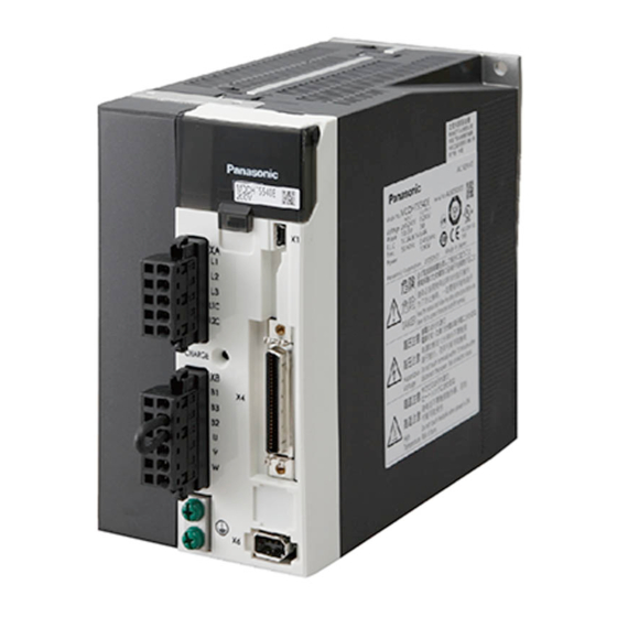
* This product image is 1.5kW type of A5E-series.
If you are the first user of this product, please be sure to read the downloaded
Operating Instructions (Overall) from our Web Site.
http://industrial.panasonic.com/ww/i_e/25000/motor_fa_e/motor_fa_e.html
Make sure to forward these Operating Instructions for safety to the final user.
<Contents>
1. Introduction ................................. B2
On Opening the Product Package .................. B2
Check of the Driver Model .............................. B2
Check of the Motor Model............................... B3
2. Installation................................... B4
Driver .............................................................. B4
Motor . .............................................................. B6
Overall Wiring (Connector type) ..................... B8
Overall Wiring (Terminal block type) .................B10
Wiring of the Main Circuit (Connector type)......... B14
Wiring method to connector ............................. B16
Wiring Diagram ............................................. B18
Wiring of connector for motor and brake ...... B19
Wiring to the Connector, X1 . ........................ B19
Wiring to the Connector, X4 . ........................ B20
Wiring to the Connector, X6 . ........................ B22
Wiring to the Connector, X7 . ........................ B22
Operating Instructions (Basic)
AC Servo Motor & Driver
[Web address of Panasonic Corporation]
page
MINAS A5E-series (400V)
• Thank you for purchasing this
Panasonic product.
• Before operating this product,
please read the instructions
carefully, and save this manual for
future use.
4. Parameter .................................. B23
Outline / Setup / Connection . ........................ B23
Composition of Parameters .......................... B25
5. Protective Functions ................ B26
Protective Function (What Is Error Code ?) ...... B26
6. Maintenance and Inspections .... B28
Composition of Peripheral Equipments ........ B32
8. Built-in Holding Brake .............. B36
9. Dynamic Brake.......................... B38
Incremental Specifications, 20-bit . .............. B39
11. Specifications ......................... B40
After-Sale Service (Repair) .......... B42
page
Advertisement
Table of Contents

Related Manuals for Panasonic MINAS A5E Series


Summary of Contents for Panasonic MINAS A5E Series
-
Page 1: Table Of Contents
* This product image is 1.5kW type of A5E-series. If you are the first user of this product, please be sure to read the downloaded Operating Instructions (Overall) from our Web Site. [Web address of Panasonic Corporation] http://industrial.panasonic.com/ww/i_e/25000/motor_fa_e/motor_fa_e.html Make sure to forward these Operating Instructions for safety to the final user. -
Page 2: Introduction
1. Introduction Check of the Motor Model 1. Introduction Contents of Name Plate On Opening the Product Package Model A C S E R V O M O T O R Rated input MSME104G1C Model No. Rated rotational speed voltage/current •... -
Page 3: Installation
2. Installation 2. Installation Driver Driver Install the driver properly to avoid a breakdown or an accident. Mounting Direction and Spacing Installation Place • Reserve enough surrounding space for effective cooling. • Install fans to provide uniform distribution of temperature in the control panel. 1) Install the driver in a control panel enclosed in noncombustible material and placed indoor • D/E/F frame is provided with a cooling fan at the bottom. where the product is not subjected to rain or direct sunlight. -
Page 4: Motor
2. Installation 2. Installation Motor Motor Install the motor properly to avoid a breakdown or an accident. 3) For the dimensions and mass of the product, which are necessary design data of the mounting section, refer to the dimensional outline drawing on the Operating In- Installation Place structions (Overall) or the Delivery Specification. -
Page 5: System Configuration And Wiring
3. System Configuration and Wiring 3. System Configuration and Wiring Overall Wiring (Connector type) Overall Wiring (Connector type) Connecting Example of D, E-frame, 400 V type : High voltage PC (to be supplied by customer) Wiring to Connector, X7 • Wiring of Main Connector (XA) Main Control •... -
Page 6: Overall Wiring (Terminal Block Type)
3. System Configuration and Wiring 3. System Configuration and Wiring Overall Wiring (Terminal block type) Overall Wiring (Terminal block type) Connecting Example of F-frame, 400 V type : High voltage PC (to be supplied by customer) Main Control • Wiring of Main Connector (XA) power supply power supply Circuit Breaker (MCCB) -
Page 7: Driver And List Of Applicable Peripheral Equipments
3. System Configuration and Wiring 3. System Configuration and Wiring Driver and List of Applicable Peripheral Equipments Driver and List of Applicable Peripheral Equipments • Select peripheral equipments for 3-phase specification according to the power Circuit Cable Cable Required Noise Applicable Rated breaker... -
Page 8: Wiring Of The Main Circuit (Connector Type)
3. System Configuration and Wiring 3. System Configuration and Wiring (Terminal block type) Wiring of the Main Circuit (Connector type) Wiring of the Main Circuit D, E-frame F-frame • Wiring should be performed by a specialist or an authorized personnel. • Wiring should be performed by a specialist or an authorized personnel. •... -
Page 9: Wiring Method To Connector
3. System Configuration and Wiring 3. System Configuration and Wiring Wiring method to connector Wiring method to connector • Follow the procedures below for the wiring connection to the Connector XA , XB , 2. Insert the cable to the connector in the following 2 methods. XC and XD . -
Page 10: Wiring Diagram
3. System Configuration and Wiring 3. System Configuration and Wiring Wiring Diagram Wiring of connector for motor and brake Compose the circuit so that the main circuit power will be shut off when an error occurs. • When the motors of <MSME (1.0 kW to 5.0 kW), MDME, MGME, MHME> are used, they are connected as shown below. -
Page 11: Wiring To The Connector, X4
3. System Configuration and Wiring 3. System Configuration and Wiring Wiring to the connector, X4 Wiring to the connector, X4 Wiring Example of Position Control Mode Wiring Example of Internal Velocity Control Mode Divider Divider − B20 − − B21 −... -
Page 12: Wiring To The Connector, X6
3. System Configuration and Wiring 4. Parameter Wiring to the connector, X6 Outline / Setup / Connection Connection to Encoder Outline of Parameter • In case of 20-bit incremental encoder This driver is equipped with various parameters to set up its characteristics and func- tions. This section describes the function and purpose of each parameter. Read and MSME 1.0kW to 5.0kW comprehend very well so that you can adjust this driver in optimum condition for your... -
Page 13: Composition Of Parameters
4. Parameter 4. Parameter Outline / Setup / Connection Composition of Parameters Setup with the PC • The parameter No. is displayed in the form of PrX.YY (X: Classification, YY: No.). • For the details on the parameters, refer to the Operating Instructions (Overall). It is possible to connect your personal computer to connector X1 of MINAS A5E using a USB cable for personal computer connection. -
Page 14: Protective Functions
5. Protective Functions 5. Protective Functions Protective Function (What Is Error Code ?) Protective Function (What Is Error Code ?) • Various protective functions are equipped in the driver. When these are triggered, the Error code Attribute Protective function motor will stall due to error, the driver will turn the Servo-Alarm output (ALM) to off (open). Main Sub History Can be cleared Immediate stop... -
Page 15: Maintenance And Inspections
6. Maintenance and Inspections 6. Maintenance and Inspections Maintenance and Inspections Maintenance and Inspections • Routine maintenance and inspection of the driver and motor are essential for Guideline for Parts Replacement the proper and safe operation. Use the table below for a reference. Parts replacement cycle varies depending on the actual operating conditions. -
Page 16: Conformity To Ec Directives And Ul Standards
115% or more than the rated current based on the time characteristics (see the CSA : Canadian Standards Association next page). Confirm that the effective current of the driver does not exceed the Pursuant to the directive 2004/108/EC, article 9(2) rated current. Set up the peak permissible current with Pr0.13 (Setup of 1st torque Panasonic Testing Centre Panasonic Service Europe, a division of limit) and Pr5.22 (Setup 2nd torque limit). Panasonic Marketing Europe GmbH Winsbergring 15, 22525 Hamburg, F.R. Germany −... -
Page 17: Composition Of Peripheral Equipments
7. Conformity to EC Directives and UL Standards 7. Conformity to EC Directives and UL Standards Composition of Peripheral Equipments Composition of Peripheral Equipments Installation Environment Noise Filter Use the servo driver in the environment of Pollution Degree 1 or 2 prescribed in When you install one noise filter at the power supply for multi-axes application, consult with IEC-60664-1 (e.g. - Page 18 7. Conformity to EC Directives and UL Standards MEMO Composition of Peripheral Equipments Noise Filter for Signal Lines Install noise filters for signal lines to all cables (power cable, motor cable, encoder cable and interface cable) Manufacturer’s Option part No. Manufacturer part No. DV0P1460 ZCAT3035-1330 TDK Corp.
-
Page 19: Built-In Holding Brake
8. Built-in Holding Brake 8. Built-in Holding Brake Outline / Specifications Outline / Specifications In the applications where the motor drives the vertical axis, this brake would be used Specifications of Built-in Holding Brake to hold and prevent the work (moving load) from falling by gravity while the power to Static Exciting Permissible... -
Page 20: Dynamic Brake
9. Dynamic Brake 10. Check of the Combination of the Driver and the Motor Outline Incremental Specifications, 20-bit This driver is designed to be used in a combination with the motor which are specified This driver is equipped with a dynamic brake for emergency stop. by us. -
Page 21: Specifications
11. Specifications 11. Specifications Basic Specifications Functions (1) Deviation counter clear (2) Command pulse inhibition + 10% Main D to 3-phase, 380 to 480V 50/60Hz Control input (3) Command dividing gradual increase switching circuit F-frame − 15% 400V (4) Damping control switching etc. Control D to Control output Positioning complete (In-position) etc. DC 24V ±15% circuit F-frame... -
Page 22: After-Sale Service (Repair)
Consult to a dealer from whom you have purchased the product for details of repair. downloaded from the following web site. When the product is incorporated to the machine or equipment you have purchased, consult to the manufacturer or the dealer of the machine or equipment. http://industrial.panasonic.com/ww/i_e/25000/motor_fa_e/motor_fa_e.html Cautions for Proper Use • This product is intended to be used with a general industrial product, but not de- signed or manufactured to be used in a machine or system that may cause personal death when it is failed. - Page 23 MEMO MEMO...
-
Page 24: Ime04
7-1-1 Morofuku, Daito, Osaka, 574-0044, Japan Phone : +81-72-871-1212 © Panasonic Corporation 2009 IME04 Printed in China Z0110-1020...
Need help?
Do you have a question about the MINAS A5E Series and is the answer not in the manual?
Questions and answers