Table of Contents
Advertisement
Quick Links
OPERATIONS MANUAL
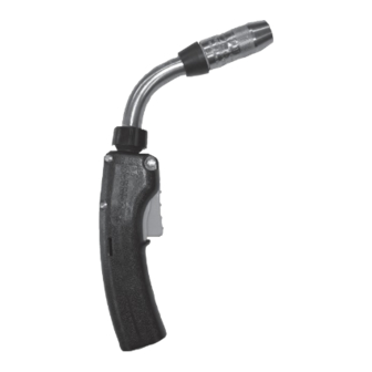
PipeWorx MIG Gun
Manufactured for Miller Global Pipe Systems
300 Amp
Part Number: 195400
SAFETY DEPENDS ON YOU!
DO NOT INSTALL, OPERATE OR REPAIR THIS
EQUIPMENT WITHOUT READING THIS OPERATING
MANUAL AND THE ARC WELDING SAFETY
PRECAUTIONS ON THE INSIDE FRONT COVER.
Bernard
®
MIG Guns are designed and built with
safety in mind, but operators must follow
prescribed safety guidelines.
Miller Electric Mfg. Co.
An Illinois Tool Works Company 1635 West Spencer
Street Appleton, WI 54914 USA
International Headquarters-USA
USA Phone: 920-735-4504 Auto-Attended USA &
Canada FAX: 920-735-4125
International FAX: 920-735-4125
European Headquarters - United Kingdom
Phone: 44 (0) 1204-593493
Fax: 44 (0) 1204-598066
MillerWelds.com
© 2023 Bernard Printed in U.S.A. DFB-OPPW-2.5
Advertisement
Table of Contents

Related Manuals for Miller Bernard PipeWorx 195400


Summary of Contents for Miller Bernard PipeWorx 195400
- Page 1 OPERATIONS MANUAL PipeWorx MIG Gun Manufactured for Miller Global Pipe Systems 300 Amp Part Number: 195400 SAFETY DEPENDS ON YOU! DO NOT INSTALL, OPERATE OR REPAIR THIS EQUIPMENT WITHOUT READING THIS OPERATING MANUAL AND THE ARC WELDING SAFETY PRECAUTIONS ON THE INSIDE FRONT COVER.
-
Page 2: Table Of Contents
TABLE OF CONTENTS SECTION 1 — SAFETY PRECAUTIONS — READ BEFORE USING 1-1 Symbol Usage 1-2 Arc Welding Hazards 1-3 California Proposition 65 Warnings 1-4 Principal Safety Standards 1-5 EMF Information SECTION 2 — CONSIGNES DE SÉCURITÉ — LIRE AVANT UTILISATION 2-1 Symboles utilisés 2-2 Dangers relatifs au soudage à... - Page 3 5-9 Rigid Strain Relief 5-10 Miller Power Pins SECTION 6 — PARTS LIST SECTION 7 — TROUBLESHOOTING 7-1 Troubleshooting Table NOTES DFB-OPPW-2.5...
-
Page 4: Section 1 - Safety Precautions - Read Before Using
SECTION 1 — SAFETY PRECAUTIONS — READ BEFORE USING Replace worn, damaged, or cracked guns or cables. Protect yourself and others from injury – read, follow, Turn off welding power source before changing contact tip or and save these important safety precautions and gun parts. - Page 5 Wear an approved welding helmet fitted with a proper shade of filter lenses to protect your face and eyes from arc rays and WELDING WIRE can injure. sparks when welding or watching (see ANSI Z49.1 and Z87.1 listed in Safety Standards). Keep hands and body away from gun tip when Wear approved safety glasses with side shields under your trigger is pressed.
-
Page 6: California Proposition 65 Warnings
1-3 California Proposition 65 Warnings WARNING: This product can expose you to chemicals For more information, go to www.P65Warnings.ca.gov. including lead, which are known to the state of California to cause cancer and birth defects or other reproductive harm. 1-4 Principal Safety Standards Safety in Welding, Cutting, and Allied Processes , American Welding Safety in Welding, Cutting, and Allied Processes , CSA Standard Society standard ANSI Standard Z49.1. -
Page 7: Section 2 - Consignes De Sécurité - Lire Avant Utilisation
SECTION 2 — CONSIGNES DE SÉCURITÉ — LIRE AVANT UTILISATION Pour écarter les risques de blessure pour vous-même et pour autrui — lire, appliquer et ranger en lieu sûr ces consignes relatives aux précautions de sécurité et UN CHOC ÉLECTRIQUE peut tuer. au mode opératoire. - Page 8 Lire et comprendre les fiches de données de sécurité et les Avertir les personnes à proximité au sujet du danger inhérent instructions du fabricant concernant les adhésifs, les au bruit. revêtements, les nettoyants, les consommables, les produits de refroidissement, les dégraisseurs, les flux et les métaux. LES FILS DE SOUDAGE peuvent provoquer L'ACCUMULATION DE GAZ risquent de des blessures.
-
Page 9: Proposition Californienne 65 Avertissements
2-3 Proposition californienne 65 avertissements AVERTISSEMENT – Ce produit peut vous exposer à des Pour plus d’informations, consulter www.P65Warnings.ca.gov. produits chimiques tels que le plomb, reconnus par l’État de Californie comme cancérigènes et sources de malformations ou d’autres troubles de la reproduction 2-4 Principales normes de sécurité... -
Page 10: Section 3 - Precauciones De Seguridad - Lea Antes De Usar
SECTION 3 — PRECAUCIONES DE SEGURIDAD — LEA ANTES DE USAR Protéjase usted mismo y a otros contra lesiones — lea, cumpla y conserve estas importantes UNA DESCARGA ELÉCTRICA puede matarlo. precauciones de seguridad e instrucciones de utilización. Siempre use guantes aislantes secos. Aíslese usted mismo del trabajo y la tierra. - Page 11 EL AMONTONAMIENTO DE GAS puede El ALAMBRE de SOLDAR puede causarle enfermarle o matarle. heridas. Mantenga las manos y el cuerpo lejos del tubo Cierre el suministro de gas comprimido de contacto de la antorcha cuando se haya cuando no lo use. presionado el gatillo.
-
Page 12: Advertencias De La Proposición 65 Del Estado De California
3-3 Advertencias de la Proposición 65 del estado de California ADVERTENCIA: Este producto puede exponerlo a químicos, Para obtener más información, acceda a incluso plomo, que el estado de California conoce como www.P65Warnings.ca.gov. causantes de cáncer, defectos de nacimiento u otros daños reproductivos. -
Page 13: Additional Information
ADDITIONAL INFORMATION Introduction Thank you for choosing Bernard. The product you have purchased has been carefully assembled and factory tested prior to shipment. Should you experience problems with installation or performance, please refer to the “Troubleshooting Guide” in this manual. Before installing, compare the equipment received against the invoice to verify that the shipment is complete and undamaged. -
Page 14: Section 4 - Installation
SECTION 4 — INSTALLATION 4-1 General Description The Bernard PipeWorx MIG Gun is designed primarily for processing mild steel electrode under GMAW (Gas Metal Arc Welding), MIG (Metal Inert Gas), MAG (Metal Active Gas), FCAW (Flux Cored Arc Welding), and MOG (Metal without Gas). The PipeWorx MIG Gun provides rapid neck interchangeability, typically during production processes. - Page 15 Contact Tips, Gas Diffusers: 1. Contact tips may be removed and rotated in gas diffuser, providing an additional wear surface and extending the service life of the product. 2. Inspect nozzle for spatter adhesion, blocked gas ports, and carburized contact surfaces. Clean as often as possible. 3.
-
Page 16: Section 5 - Maintenance And Repair
SECTION 5 — MAINTENANCE AND REPAIR See page 10 for the parts list. Disconnect gun from equipment, allow to cool, and remove electrode from liner before servicing. 5-1 Nozzle A. Removal Threaded fit nozzle can be removed by turning in a counter- clockwise direction. B. -
Page 17: Neck
Firmly secure gas diffuser with an appropriate wrench in a clockwise rotation, torque to 144 in-lbs. Be sure insulator cap is in place as shown in figure #1. 5-4 Neck A. Removal Grasp lock nut and rotate counterclockwise, rotation will free neck from end fitting. B. -
Page 18: Cable
5-7 Cable A. Inspection Replace the cable assembly if the following conditions are evident on the exterior of the cable: cuts and/or abrasions in cable jacketing exposing copper stranding, abrupt kinking of cable causing abnormal heating in area of bend, loss of control circuit function as verified through continuity tests, slippage of insulating jacket exposing copper stranding, or crushed cable. -
Page 19: Rigid Strain Relief
Torque screw to 12 in-lbs (1.4 Nm). Using the arrows on the cap to align with mating grooves, slide the cap and sleeve assembly toward the rigid strain relief until seated, and turn clockwise until engaging snap is felt. 5-10 Miller Power Pins A. Removal Remove the power pin tip that retains the liner from the power pin with the appropriate wrench. -
Page 20: Section 6 - Parts List
SECTION 6 — PARTS LIST ITEM Part # Description NS-5818C Nozzle T-045 Contact Tip DS-1 Diffuser 4523R 1840057-2 Q-Nut Insulator, Front Neck ( Includes neck and QT2-60 items #5, #7, #8 ) 1840057-1 Q-Neck Cover 1840031 Q-Neck Insulator, Rear QJL-3545 Jump Liner Handle Kit ( Includes 1880219... -
Page 21: Section 7 - Troubleshooting
SECTION 7 — TROUBLESHOOTING 7-1 Troubleshooting Table PROBLEM POSSIBLE CAUSE CORRECTIVE ACTION 1. Electrode does not feed. 1. Feeder relay. 1. Consult feeder manufacturer. 2. Broken control lead. 2. a. Test and connect spare control lead. b. Install new cable. 3. - Page 22 8. Porosity in weld. 1. Insulator worn. 1. Replace nozzle / insulator. 2. Gas diffuser damaged 2. Replace gas diffuser. 3. Extreme heat or duty cycle. 3. Replace with heavy duty consumables. 4. Solenoid faulty. 4. Replace solenoid. 5. No gas. 5.
-
Page 23: Notes
NOTES DFB-OPPW-2.5...
Need help?
Do you have a question about the Bernard PipeWorx 195400 and is the answer not in the manual?
Questions and answers
I need the part # for male and female remote connector
The part numbers for the male and female remote connectors for the Miller PipeWorx 195400 are not provided in the given context.
This answer is automatically generated