Advertisement
Quick Links
Installation Instructions
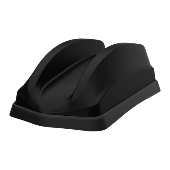
Dual Sharkee ®
FIND4/GPS[X]D4[X]/SHK[X]4[X]-6-60[-X]
SW3-1025 - v3
1. Introduction
The FIND4/GPS[X]D[X]4/SHK[X]G[X]4 series is a multi-function sharkfin style antenna with 4x4 MiMo for 4G/5G. The GPS[X]D[X]4/SHK[X]G[X]4 incor-
porates either a single or multiple GPS/ GNSS antennas with 26dB gain LNA or single or multiple L1/L5 antennas with up to 30dB LNA gain. The GPS[X]
D4 type features an M6 mounting stud for an optional comms whip. Note: The SHK[G]4 type does not have this feature. Versions are available which can
include up to 6x6 MiMo dual band WiFi 6e function. The antenna is suitable for fitment to vehicle panels up to 4mm (0.15") thick. An extended mounting kit
for thicker panels is available as an accessory.
Electrical Safety Note
The standard GPS[X]D4/SHKG4 contain single or multiple active GPS/GNSS antennas. Rated voltage: 3-5VDC Rated current (each antenna):
20mA maximum.
The GPSD54/SHKG54 contain a single active GPS/GNSS antenna. Rated voltage: 3-5VDC. Rated current: 37mA maximum.
The supply to these devices must be provided with over current protection of 1A maximum.
2. Mounting requirements and selecting location
For optimum performance, it is recommended that all versions of the antenna are fitted on a conductive (metal) panel, although it is possible to mount the
antenna on a non-conductive panel with acceptable performance for all the internal antenna functions. For GPS[X]D4 type, when a whip is to be used, the
antenna must be fitted on a conductive ground plane - recommended minimum size is 1⁄2 wave length diameter at the lowest frequency of whip operation.
To calculate this size, use formula below:
When fitting on a non-metallic panel, a ground plane plate of suitable size should be fabricated and fitted under the mounting panel. In all cases, the
earthing washer must make low resistance electrical contact with the ground plane (<0.2Ω). Select a mounting location, checking for roof curvature
to ensure that the antenna base will have a flat mounting surface if possible. The antenna should be located as far as possible from surrounding roof
mounted items (e.g light bar, air con unit). Ensure that there is adequate under panel clearance and that there is no double skin panel or cross brace
present. Measure to check for central position if applicable.
Important Note Regarding Sealing
To ensure that the antenna base is effectively sealed against the mounting surface, care must be taken regarding curvature of the mounting panel.
It is highly recommended that the antenna is installed on a clean, flat and level surface. After installation the compression of the rubber boot against
the mounting panel should be checked and if necessary, a small bead of neutral cure silicone sealant can be applied around the edge of the
mounting boot. It is important that the periphery of the antenna is sealed and that no moisture is allowed to penetrate under the antenna boot.
3. Prepare and drill hole
Up to 13 cables fitted with standard (SMA/FME) connectors, or 12 cables fitted with FAKRA type connectors can pass through a 19mm (3/4") clearance
hole. If other connector types are fitted or the number of feeds exceeds these limits, you may need to consider drilling a larger mounting hole.
Mask panel area around hole position to protect paintwork and headliner. Drill a pilot hole, and then increase to 19mm
(3/4"), ensuring that drill/cutter bit does not contact headliner. Clean area around the hole, carefully removing any burrs
and swarf. Remove paint and primer from under panel surface to ensure low resistance contact by washer and nut.
Apply some petroleum jelly or paint around the hole to prevent corrosion.
50 / frequency in MHz = 1⁄2 wavelength (m)
Example: 150MHz =100cm (39.4"); 400MHz = 38cm (15"); 900MHz =16cms (6.3").
Advertisement

Related Manuals for Panorama Antennas FIND4 Series


Summary of Contents for Panorama Antennas FIND4 Series
- Page 1 Installation Instructions Dual Sharkee ® FIND4/GPS[X]D4[X]/SHK[X]4[X]-6-60[-X] SW3-1025 - v3 1. Introduction The FIND4/GPS[X]D[X]4/SHK[X]G[X]4 series is a multi-function sharkfin style antenna with 4x4 MiMo for 4G/5G. The GPS[X]D[X]4/SHK[X]G[X]4 incor- porates either a single or multiple GPS/ GNSS antennas with 26dB gain LNA or single or multiple L1/L5 antennas with up to 30dB LNA gain. The GPS[X] D4 type features an M6 mounting stud for an optional comms whip.
- Page 2 4. Fitting the antenna Remove protective backing from underside of antenna, feed coaxial cables through panel. Position the antenna over the hole ensuring correct orientation and stick to panel by applying firm, even, downward pressure. When fitting the nut, it is important to ensure that the cables are held centrally whilst the nut is correctly started on the threads.
- Page 3 7. Notices CAUTION Consider relevant RF exposure rules. Ensure that the antenna is installed to provide a minimum separation distance of at least 20 cm (8”) from all persons during use. DO NOT • operate the transmitter when someone is within 20 cm (8”)of the antenna. •...
Need help?
Do you have a question about the FIND4 Series and is the answer not in the manual?
Questions and answers