
Related Manuals for PHP 55AG


Summary of Contents for PHP 55AG
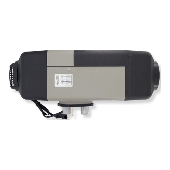
- Page 1 ® 55AG AIR HEATER Technical Description Installation Instructions Operating Instructions Troubleshooting...
-
Page 3: Table Of Contents
Table of Contents Introduction Heater Warnings Speci cations Heater Kit List Main Components and Operating Concepts Heater Mounting Fuel System Electrical Connections Operating Switch Instructions Exhaust & Combustion Air Intake Connections Heater Ducting Heater Operation Maintenance Troubleshooting Fault Code Chart Heater Components... -
Page 4: Introduction
Introduction Thank you for purchasing our 55AG heater. The 55AG heater is designed to provide cabin heating for trucks, RVs, Vans/Buses, and Mobile Workshops by using on-board gasoline fuel and battery systems. Operation is simple and the heater provides a safe and reliable alternative to engine idling or need for electrical plugins This heater is designed to operate continuously at altitudes up to 5,000 m (16,404’) above... -
Page 5: Heater Warnings
Heater Warnings Special Notes Note: Highlight areas requiring special attention or clari cation. Caution Indicates that personal injury or damage to equipment may occur unless speci c guidelines are followed. Warning Indicates that serious or fatal injury may result if speci c guidelines are not followed. Warning - Asphyxiation Hazards Warning - Installation Hazards •... -
Page 6: Speci Cations
Speci cations Principal Dimensions 148 mm 425 mm 90 mm 90 mm 162 mm 25 mm 24 mm 25 mm 151 mm Performance Specifications Heating Mode (Variable) High Range Low Range Heating Capacity kW/hr (BTUs/hr) 5.0 (6,824) 1.4 (4,777) 0.66 (0.17) 0.19 (0.05) Fuel Consumption L/hr (US Gal/hr) Air Flow M^3/min (CFM) -
Page 7: Heater Kit List
Heater Kit List Description Part Number 5 kW Air Heater P55A-T888 Description Part Number Operating Switch P65A-X388 Description Part Number Heater Mounting Plate & Seal U65A-X702 Description Part Number Wiring Harness P55A-X303 4.5M (15’) Power Harness, 20A Fuse 6M (20’) Switch Harness 4.5M (15’) Fuel Pump Harness U65D-X305 Description... - Page 8 Heater Kit List Description Part Number Fuel Metering Pump P55A-T410 Fuel Pump Holder U65D-X407 Black Rubber Fuel Line, 4.5mm ID x 0.5M U65D-X414 4.5mm ID x 50mm Fuel Line Connectors U65D-X409 Clear Nylon Fuel Line, 8M (26’),1.5 - 2.0 mm ID U65D-X403 Small Fuel Line Clamps, 9-11 mm x 9mm wide U65D-X401...
-
Page 9: Main Components And Operating Concepts
Main Components and Operating Concept Main Components 1) Process Air Blower 6) Blower Motor C. Combustion Air 2) Control Unit 7) Glow Pin E. Exhaust Gas 3) Combustion Air Blower 8) Fuel Metering Pump F. Fresh Air Intake 4) Combustion Chamber & Heat Exchanger 9) Operating Switch H. -
Page 10: Heater Mounting
Heater Mounting Heater Location Typically, air heaters are mounted inside a tool compartment with the OEM HVAC System. However, the heater may be mounted anywhere inside the cabin provided you adhere to the following conditions: • Combustion air intake, exhaust and fuel inlet connections must be on outside of the vehicle. - Page 11 Heater Mounting Mounting • A mounting plate and hardware are provided with the truck heater kit. • Refer to Figures M2 & M3 for assembly orientation. Note: If the mounting plate will not be used, the heater ange can be used as a template to mark where the individual components openings should be made.
- Page 12 Heater Mounting Figure M3 Figure M4 4” x 5” Rectangle Ø3” x 2 2 1/8”...
-
Page 13: Fuel System
Fuel System Overview The 55AG fuel pump and fuel system are the heart of the heater. The fuel pump not only delivers fuel to the heater but also controls the amount of fuel delivered. The pump is designed to operate like an electric solenoid and works using electric pulses. - Page 14 Fuel System Connecting the Fuel System Caution Fuel systems in gasoline vehicles are sealed and electronically monitored to contain fuel vapors. When integrating the heater, you must ensure that you do not disrupt the integrity of the fuel system. Installation should only be completed by a competent technician familiar with the fuel system of the vehicle. Due to the in nite variations of fuel systems used in Gasoline powered vehicles, it is impossible to provide a standard fuel pickup device or procedure that works for every application.
- Page 15 Fuel System Auxiliary Fuel Port Method In some instances, the vehicle may have an auxiliary fuel port. It is possible to use this as fuel tank access. Consult the vehicle dealer for appropriate connections to adapt to our 4.5 mm rubber fuel line. Tee Into Fuel Line Method (NOT RECOMMENDED) Parking Heater Products recommends against Teeing into the vehicles fuel line.
- Page 16 Fuel System Auxiliary Fuel Tank Method Auxiliary fuel tanks can be used in some cases as a solution for di cult to access fuel tanks. However, these are not certi ed for on-road use. Standard Fuel Pickup Method (Metal tank only) Standard fuel pickup pipes can be installed in larger metal tanks only.
- Page 17 Fuel System Fuel Filter • An optional fuel lter is provided with your installation kit. • If used, it should be replaced every two years. • Mount between the fuel pump and tank. • Mount on an incline to allow air to pass through. •...
-
Page 18: Electrical Connections
Electrical Connections Electrical System Installation The heater harness has all the electrical connections preassembled for easy installation. Route cables using either an existing cable passage or drill holes as required. Seal the hole around the cables and make sure they are protected from cha ng and pinching. Below is a summary of the wiring connections required. - Page 19 Electrical Connections 55AG Wiring Diagram Figure E2 ECU Interfaces The following represents the wiring connector locations for the ECU. The connectors are constructed to ensure that it is impossible to connect in error. Figure E3 Socket X1 Fan Motor Socket X2...
-
Page 20: Operating Switch Instructions
Operating Switch Instructions The 55AG is provided with a multi-functional operating switch. It is capable of manual and timer controlled switching of the heater and conveys heater operational parameters and diagnostics. Mount the operating switch in a suitable location using panel mount method shown in Figure S1 Route the switch harness from the heater to the Operating Switch and connect. - Page 21 Operating Switch Instructions Buttons & Display Icons Buttons: ON / OFF On / O Control Adjust heat settings < Toggle through menu > Adjust heat settings Toggle through menu Select Menu settings Icons: Heating Mode Fan Mode Not Used Program Mode Clock Settings...
- Page 22 Operating Switch Instructions Set Time of Day / Day of Week: 1. Press “OK” Icons Displayed and heat symbol ashing 2. Press “>” or “<” repeatedly to select “Clock” Icon Clock Icon ashes 3. Press “OK” Days of week are displayed 4.
- Page 23 Operating Switch Instructions On / O Control 1. Press “OK” Icons Displayed and heat symbol ashing 2. Press “>” or “<” repeatedly to select “Heat” Icon Heat Icon ashes Press “OK” Heater commences start up mode Current Power Level Setting or Target Temperature Setting of heater is displayed.
- Page 24 Operating Switch Instructions Adjusting Power Mode With heater operating in “Power Mode”, Press “>” or “<” to adjust setting from 1-7 1 is lowest and 7 is highest Display will show current target Power Mode setting Heater will continue to operate in this heat output level.
- Page 25 Operating Switch Instructions 3. Press “OK” Fan Speed Setting is displayed 4. Press “>” or “<” to adjust fan speed setting 1-7 Fan Speed Setting is displayed 5. Press the “On / O ” Button to switch o the fan Home Screen displayed Programmed Startup The operating switch has the ability to automatically start the heater using programmed start up and shut...
- Page 26 Operating Switch Instructions 5. Press “OK” to select desired pro le setting Status “On” or “O ” displayed. 6. Press “>” or “<”to select “ON” or “OFF” Status “On” or “O ” displayed. 7. Press “OK” Run Time displayed 8. Press “>” or “<” to adjust run time for this pro le. 10 -990 minutes Run Time displayed 9.
- Page 27 Operating Switch Instructions 13. Press “OK” Days of Week settings are displayed. “Mo” ashing 14. Press “>” or “<”to adjust between “On” or “O ” to activate or deactivate programmed start for that day. “O ” or “On” displayed 15. Press “OK” to proceed to next day Days of Week settings are displayed.
- Page 28 Operating Switch Instructions Fuel System Priming On initial start up after installing the heater, the system has the ability to conduct a fuel system priming function. 1. Press “OK” Icons Displayed and heat symbol ashing 2. Press “>” or “<” repeatedly to select “Clock” Icon Clock Icon ashes 3.
-
Page 29: Exhaust & Combustion Air Intake Connections
Exhaust & Combustion Air Intake Connections Figure A1 25mm Combustion Air Intake 24mm Exhaust Min. 0.4M (8”) Min. 0.4M (8”) Max. 1.0M (39”) Max. 2.0M (78”) Figure A2 Direction of travel... - Page 30 Exhaust & Combustion Air Intake Connections The combustion air intake tube channels clean air into the heater. The exhaust tube channels exhaust safely away from the heater and vehicle. It also assists in providing a required amount of back pressure required to balance the combustion process. Connect the combustion air intake tube and exhaust as shown in Figure A1 Exhaust Considerations: •...
-
Page 31: Heater Ducting
Heater Ducting Hot Air Ducting Distribute heat e ciently throughout the cabin by using the high temperature, 90mm ex-ducting and rotatable outlet and return air inlet provided in the installation kit. IMPORTANT NOTE: The heater uses a temperature sensor on the inlet side of the heater to regulate the cabin temperature. Use return air ducting for best heating regulation and e ciency. -
Page 32: Heater Operation
Heater Operation 55AG Operation Note: It is important to understand that this heater does not simply turn on and turn o . Rather, it has a sophisticated operating system similar to a household furnace to provide reliable heating comfort. The operator should familiarize themselves with the normal operation of the heater. - Page 33 Heater Operation “Vent Mode” Runs the blower fan only to provide cabin ventilation. The operator can adjust the fan speed in a range from 1-7. Note: Running the fan in vent mode for extended periods will diminish the life expectancy of the motor. Automatic Start Times The heater can has the capability of starting and running automatically with pre de ned start up and run times.
- Page 34 Heater Operation Safety Systems The heater is equipped with several control features to protect itself and the operator. Systems Check: The heater will not attempt to start if one of the components is detected by the control unit to be defective.
-
Page 35: Maintenance
Maintenance • Switch heater ON at least once monthly for 10 minutes • Clear combustion air supply and the exhaust system after longer standstill periods. • Ensure that the vehicle batteries are maintained • Inspect and clean all electrical connections and apply dielectric grease. •... -
Page 36: Troubleshooting
Self Diagnostics The 55AG has an automatic built in error code detection system. When the heater detects a fault, it should display a two-digit error code on the Operating Switch. Refer to the Fault Codes section of this manual for further direction. - Page 37 Troubleshooting Fuel Ensure you are supplying a good quality fuel. Fuel is not frozen or gelled Fuel system falls within parameters outlined in installation section. All connections are secure and there are no air leaks Try removing the fuel line at the heater during start up to ensure that fuel is being delivered. Check for fuel lter or fuel metering pump blockage.
-
Page 38: Fault Code Chart
Fault Code Chart Fault Code Cause of trouble Remedy Failure to start on two attempts Check for combustion issues (see manual section) Failure to start on three attempts Check for combustion issues (see manual section) Failure to recognize start, ame sensor Check for combustion issues (see manual section) temperature not high enough. - Page 39 Fault Code Chart Fault Code Cause of trouble Remedy Blower Motor Open Circuit Replace as necessary Blower Motor Short Circuit Replace as necessary Blower Speed Too Slow Replace as necessary Blower Speed Too High Replace as necessary Blower Speed Measurement Fault Replace as necessary Glow Pin Short Circuit Should be approximately 0.7...
-
Page 40: Heater Components
Heater Components 55AG Replacement Parts Heater Casing... - Page 41 Heater Components 55AG Replacement Parts Item Description Part Number ECU (Control Unit) P55A-T301 Glow Pin / Flame Sensor P55A-T102 Blower Assembly P55A-T101 Blower Gasket P55A-X104 Burner Insert P55A-X103 Burner Tube P55A-X102 Burner “O” Ring P55A-X105 Heat Exchanger P55A-X106 Overheat Sensor...
- Page 44 ® Vancouver Toronto Dallas help@dksi.com 877-508-3900 DKSI.com PHP-092024-TM55A-REV00...
Need help?
Do you have a question about the 55AG and is the answer not in the manual?
Questions and answers