
Related Manuals for PHP PH21A


Summary of Contents for PHP PH21A
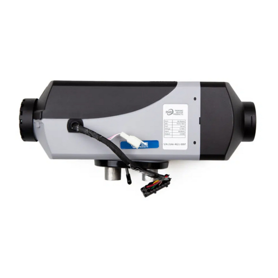
- Page 1 ® PH21A AIR HEATER Technical Description Installation Instructions Operating Instructions Troubleshooting...
-
Page 2: Table Of Contents
Table of Contents Introduction Heater Warnings Specifications Heater Kit List Main Components and Operating Concept Heater Mounting Fuel System Electrical Connections Operating Switch Exhaust & Combustion Air Intake Connections Heater Ducting Heater Operation Maintenance Troubleshooting Fault Code Chart Heater Components... -
Page 3: Introduction
Introduction Thank you for purchasing our PH21A heater kit. The PH21A heater is designed to provide cabin heating for trucks, off-highway equipment, RVs and boats by using on-board diesel fuel and battery systems. Operation is simple and the heater provides a safe and reliable alternative to engine idling or need for electrical plug ins. -
Page 4: Heater Warnings
Heater Warnings Special Notes Note: Highlight areas requiring special attention or clarification. Caution Indicates that personal injury or damage to equipment may occur unless specific guidelines are followed. Warning Indicates that serious or fatal injury may result if specific guidelines are not followed. Warning - Asphyxiation Hazards Warning - Installation Hazards •... -
Page 5: Specifications
Specifications Principal Dimensions 116 mm 335 mm (4.57”) (13.19”) Ø60 mm Ø60 mm 123 mm (2.36”) (2.36”) (4.84”) Ø25 mm Ø24 mm (0.98”) (0.95”) Performance Specifications Heating Mode Super High Medium 2.0 (6,850) 1.5 (5,800) 1.1 (4,437) 0.9 (3,072) Heating Capacity kW/hr (BTUs/hr) 0.21 (0.07) 0.16 (0.06) 0.12 (0.04) -
Page 6: Heater Kit List
Heater Kit List Description Part Number 2Kw Air Heater P21A-T801 Description Part Number Operating Switch P65A-X310 Mount Bracket Description Part Number Heater Mounting Plate & Seal U65A-X702 Description Part Number Wiring Harness 4.5M (15’) Power Harness, 20A Fuse P65A-X303 4.5M (15’) Fuel Pump Harness 6M (20’) Switch Harness Description Part Number... - Page 7 Heater Kit List Description Part Number Fuel Metering Pump P21A-T401 Fuel Pickup Tube & Fuel Tube Hardware Kit U65D-X405 Fuel Pump Holder U65D-X407 Black Rubber Fuel Line, 4.5mm ID x 0.5M U65D-X414 4.5mm ID x 50mm Fuel Line Connectors U65D-X409 Clear Nylon Fuel Line, 8M (26’),1.5 - 2.0 mm ID U65D-X403 Small Fuel Line Clamps, 9-11 mm x 9mm wide...
-
Page 8: Main Components And Operating Concept
Main Components and Operating Concept 1) Process Air Blower 6) Blower Motor C. Combustion Air 2) Control Unit 7) Glow Pin E. Exhaust Gas 3) Combustion Air Blower 8) Fuel Metering Pump F. Fresh Air Intake 4) Combustion Chamber & Heat Exchanger 9) Operating Switch H. -
Page 9: Heater Mounting
Heater Mounting Heater Location Typically, air heaters are mounted inside a tool compartment with the OEM HVAC System. However, the heater may be mounted anywhere inside the cabin provided you adhere to the following conditions: • Combustion air intake, exhaust and fuel inlet connections must be on outside of the vehicle. - Page 10 Heater Mounting Mounting • A mounting plate and hardware are provided with the truck heater kit. • Refer to Figures M2 & M3 for assembly orientation. Note: If the mounting plate will not be used, the heater flange can be used as a template to mark where the individual components openings should be made.
- Page 11 Heater Mounting Figure M3 Heater Flange Wiring Harness Seal Exhaust Combustion air Fuel Line...
- Page 12 Heater Mounting Figure M4 4” x 5” Rectangle Ø3” x 2 2 1/8”...
-
Page 13: Fuel System
Fuel System The PH21A fuel pump and fuel system are the heart of the heater. The fuel pump not only delivers fuel to the heater but also controls the amount of fuel delivered. The pump is designed to operate like an electric solenoid and works using electric pulses. - Page 14 Fuel System Figure F2 Figure F3 Fuel Pump Mounting • Using the bracket and rubber mount provided, install fuel pump as shown in Figure F2. • Isolating the pump with the rubber holder helps to minimize noise created during operation. •...
- Page 15 Fuel System Fuel Pick-Up Pipe Installation (Drill Option) • Drill mounting holes in tank to accommodate pick-up pipe as shown in Figure F4 • Drill the two (1/4”) holes first as shown in Figure F5. • Drill a 7/8” hole as shown in Figure F6. •...
-
Page 16: Electrical Connections
Electrical Connections Electrical System Installation The heater harness has all the electrical connections pre-assembled for easy installation. • Route cables using either an existing cable passage or drill holes as required. • Seal the hole around the cables and make sure they are protected from chaffing and pinching. •... - Page 17 Electrical Connections Main Harness Wiring Legend Terminal Wire Color Function Terminal Wire Color Function Main Power “ + ” Open Brown / White Switch Green / Red Fuel Metering Pump Blue / White Switch Brown Fuel Metering Pump Yellow Switch Open Open Open...
- Page 18 Electrical Connections Operating Switch Wiring Figure E5 Brown Brown Brown / White Black Yellow Red / White Grey Blue / White Grey / Red Viewed from wire side of connectors Female Male...
-
Page 19: Operating Switch
Operating Switch Instructions Overview: The PHP Operating Switch allows you to regulate cabin temperature, set operating mode, monitor heater operations and access diagnostic information. Operation Buttons & Display Icons: Altitude Cabin Temperature Combustion Efficiency Fuel Reservoir Temperature Setting Battery Operating Switch... - Page 20 Operating Switch Instructions ON / Off Control: ON / Off Control: On / Off Control: Press and hold the Operating Switch for 3 seconds to turn the heater either ON or OFF. Press & Hold Press and hold the Operating Switch for 3 seconds to turn the heater either ON or OFF.
- Page 21 Operating Modes: The heater has two different operating modes. Operating Modes: Operating Modes: The heater has two different operating modes. “Power Mode” Controls the heat output level. The heater has two different operating modes. Operating Switch Instructions “Power Mode” Controls the heat output level. “Automatic Mode”...
- Page 22 Operating Switch Instructions Auxiliary Fuel Reservoir Monitor If an auxiliary fuel reservoir is used; Auxiliary Fuel Reservoir Monitor: Press & Hold If an auxiliary fuel reservoir is used; Operating Switch can monitor fuel levels to advise when refueling is necessary. Operating Switch can monitor fuel levels to advise when refueling is necessary.
-
Page 23: Exhaust & Combustion Air Intake Connections
Exhaust & Combustion Air Intake Connections The combustion air intake tube channels clean air into the heater. The exhaust tube channels exhaust safely away from the heater and vehicle. It also assists in providing a required amount of back pressure required to balance the combustion process. Connect the combustion air intake tube and exhaust as shown in Figure A1 Exhaust Considerations: •... - Page 24 Exhaust & Combustion Air Intake Connections Figure A1 25mm Combustion Air Intake 24mm Exhaust Min. 0.4M (8”) Min. 0.4M (8”) Max. 1.0M (39”) Max. 2.0M (78”) Figure A2 Direction of travel...
-
Page 25: Heater Ducting
Heater Ducting Hot Air Ducting Distribute heat efficiently throughout the cabin by using the high temperature, 60mm flex-ducting and rotatable outlet and return air inlet provided in the installation kit. IMPORTANT NOTE: The heater uses a temperature sensor on the inlet side of the heater to regulate the cabin temperature. Use return air ducting for best heating regulation and efficiency. -
Page 26: Heater Operation
Heater Operation Starting The Heater Note: It is important to understand that this heater does not simply turn on and turn off. Rather, it has a sophisticated operating system similar to a household furnace to provide reliable heating comfort. The operator should familiarize themselves with the normal operation of the heater. - Page 27 Heater Operation Shut Down Process Caution The heater should only be controlled using the operating switches provided. Switching the heater off by interrupting it’s power source will bypass the heater’s normal cool down process and will cause stress and premature wear of the combustion components. Switching Off –...
- Page 28 Heater Operation Voltage: If the lower or upper voltage limit is reached, the heater will turn OFF after a 20 second delay. Fan Speed: The fan speed is continuously monitored. If the fan motor does not start or if the speed deviates by more than 40%, the heater will turn OFF after 60 seconds.
-
Page 29: Maintenance
Maintenance • Switch heater ON at least once monthly for 10 minutes • Clear combustion air supply and the exhaust system after longer standstill periods. • Ensure that the vehicle batteries are maintained • Inspect and clean all electrical connections and apply dielectric grease. •... -
Page 30: Troubleshooting
Self Diagnostics The PH21A has an automatic built in error code detection system. When the heater detects a fault, it should display a two-digit error code on the Operating Switch. Refer to the Fault Codes section of this manual for further direction. - Page 31 Troubleshooting Fuel Ensure you are supplying a good quality diesel fuel. Fuel is not frozen or gelled Fuel system falls within parameters outlined in installation section. All connections are secure and there are no air leaks Try removing the fuel line at the heater during start up to ensure that fuel is being delivered. Check for fuel filter or fuel metering pump blockage.
-
Page 32: Fault Code Chart
Fault Code Chart Error Code Description of Error Diagnostic Instruction & Correct Action & Repair Communications Error Check all wiring to heater. Reboot ECU by removing main fuse for 5 minutes. Replace ECU as necessary Failed Ignition Heater does not start successfully within start up period. (Two attempts) Refer to Combustion Issues in manual. -
Page 33: Heater Components
Heater Components... - Page 34 Heater Components PH21A Replacement Parts Note: Refer to Kit List section for additional part listing. Item Description Part Number Blower Motor Assembly P21A-T101 Blower Gasket E20A-X102 P21A-T301 Temperature Sensor P65A-X104 Glow Pin Screen (Includes Insert Tool) P65A-X102 Glow Pin (Includes Split Socket)
- Page 36 ® Vancouver Toronto Dallas help@dksi.com 877-508-3900 DKSI.com PHP-032022-TM21A-REV2...
Need help?
Do you have a question about the PH21A and is the answer not in the manual?
Questions and answers