
Related Manuals for PHP PHP-40A


Summary of Contents for PHP PHP-40A
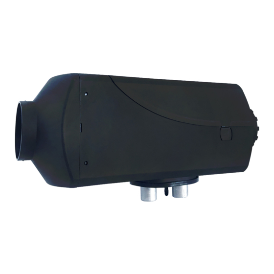
- Page 1 ® PHP-40A AIR HEATER Technical Description Installation Instructions Operating Instructions Maintenance & Troubleshooting...
-
Page 2: Table Of Contents
Table of Contents Introduction Heater Warnings Specifications Heater Kit List Main Components and Operating Concept Heater Mounting Fuel System Electrical Connections Operating Switch Exhaust & Combustion Air Intake Connections Heater Ducting Heater Operation Maintenance Troubleshooting Fault Code Chart... -
Page 3: Introduction
Introduction Thank you for purchasing our PHP-40A heater kit. The PHP-40A heater is designed to provide cabin heating for larger truck sleepers, off-highway equipment, RVs and boats by using on-board diesel fuel and battery systems. Operation is simple and the heater provides a safe and reliable alternative to engine idling or need for electrical plug ins. -
Page 4: Heater Warnings
Heater Warnings Special Notes Note: Highlight areas requiring special attention or clarification. Caution Indicates that personal injury or damage to equipment may occur unless specific guidelines are followed. Warning Indicates that serious or fatal injury may result if specific guidelines are not followed. Warning - Asphyxiation Hazards Warning - Installation Hazards •... -
Page 5: Specifications
Specifications Principal Dimensions Performance Specifications Heating Mode Super High Medium Heating Capacity kW/hr (BTUs/hr) 4.0 (13,500) 3.5 (11,800) 2.1 (7,100) 1.0 (3,412) Fuel Consumption L/hr (US Gal/hr) 0.5 (0.13) 0.4 (0.10) 0.3 (0.08) 0.11 (0.03) Air Flow - CFM Power Consumption - watts Power Consumption at Start - watts ≤... -
Page 6: Heater Kit List
Heater Kit List Description Part Number 4Kw Air Heater P40A-T802 Heater Only Description Part Number Operating Switch P65D-T303 2 Sided Mounting Tape Description Part Number Mounting Plate U65A-X702 Mounting Plate Seal U65A-X701 Description Part Number Wiring Harness 3.2M (10.5’) Power Harness, 30A Fuse 2.5M (8’) Fuel Pump Harness 2M (6’) Switch Harness Description... - Page 7 Heater Kit List Description Part Number Fuel Pickup Tube & Fuel Tube Hardware Kit U65D-X405 - Compression Fitting - Large Flat Washer - Small Flat Washer - Large Rubber Gasket - Large Hex Nut - Brass Hex Nut - Brass Securing Body Fuel Metering Pump P20A-T401 Fuel Pump Holder...
-
Page 8: Main Components And Operating Concept
Application of the PHP-23A Air Heater The PHP-23A Air Heater is designed to be used as an auxiliary and sometimes primary heater in car, trucks, RVs, boats, buses, construction and farm equipment. The heater provides heat using the vehicles fuel and battery power without the need for the vehicle engine to waste fuel by idling just to provide heat. -
Page 9: Heater Mounting
Failure to comply with the regulations, safety instructions, installation instructions or having repairs performed by unauthorized persons or use of aftermarket parts voids the heater warranty and relieves the manufacturer, distributors, dealers, and installation technicians from any and all liabilities. The installer is responsible for all damages to the property or person that arises from faulty installation of the heater. - Page 10 Heater Mounting Mounting • A mounting plate and hardware are provided with the truck heater kit. • Refer to Figures M2 & M3 for assembly orientation. Note: If the mounting plate will not be used, the heater flange can be used as a template to mark where the individual components openings should be made.
- Page 11 Heater Mounting Figure M3 Heater Flange Wiring Harness Seal Exhaust Combustion air Fuel Line...
- Page 12 Heater Mounting Figure M4 4” x 5” Rectangle Ø3” x 2 2 1/8”...
-
Page 13: Fuel System
Fuel System The PHP-40A fuel pump and fuel system are the heart of the heater. The fuel pump not only delivers fuel to the heater but also controls the amount of fuel delivered. The pump is designed to operate like an electric solenoid and works using electric pulses. - Page 14 Fuel System Figure F2 Figure F3 Fuel Pump Mounting • Using the bracket and rubber mount provided, install fuel pump as shown in Figure F2. • Isolating the pump with the rubber holder helps to minimize noise created during operation. •...
- Page 15 Fuel System Fuel Pick-Up Pipe Installation (Drill Option) • Drill mounting holes in tank to accommodate pick-up pipe as shown in Figure F4 • Drill the two (1/4”) holes first as shown in Figure F5. • Drill a 7/8” hole as shown in Figure F6. •...
-
Page 16: Electrical Connections
Electrical Connections Electrical System Installation The heater harness has all the electrical connections preassembled for easy installation. • Route cables using either an existing cable passage or drill holes as required. • Seal the hole around the cables and make sure they are protected from chaffing and pinching. •... - Page 17 Electrical Connections Main Harness Wiring Legend Open end view of main heater harness connector Note: There are no corresponding numbers on the connector. Numbers are for reference only. Terminal Wire Color Function White Switch Blue Switch Yellow Fuel Pump Red / White Main Power “+”...
-
Page 18: Operating Switch
Operating Switch Figure E2 The PHP-40A is provided with a multifunctional controller. It is capable of manual and timer controlled switching of the heater and conveys heater operational parameters and diagnostics. Refer to the Operating Switch Instructions for operational details. - Page 19 It also facilitates troubleshooting by providing diagnostic codes. Overview: The PHP Control Switch allows you to set and regulate temperature, set operating mode, timed shutdown and timed startup functions. It also facilitates troubleshooting by providing diagnostic codes. Operation Buttons and Display Icons:...
- Page 20 Operating Switch PHP Gen II Air Heater Control Switch - Operation Instructions Operating Modes: Operating Modes: The heater is designed to function in two different operating modes. The heater is designed to function in two different operating modes. “Gear” mode (Manual) allows you to control the heater output mode in 4 operating levels.
- Page 21 Operating Switch PHP Gen II Air Heater Control Switch - Operation Instructions Timed Shutdown (Heater must be operating) To set the timed shutdown (Operating Duration): Count down time will be displayed. Start the heater Activate the Timed Shutdown Status mode using the Operating Status button menu.
- Page 22 PHP Gen II Air Heater Control Switch - Operation Instructions Timer Functions: The Heater Control Switch displays the current operating time using a 24 hour clock. Operating Switch It can also be used to automatically turn the heater on then off at a desired preset time.
- Page 23 Operating Switch PHP Gen II Air Heater Control Switch - Operation Instructions Set Automatic Start Time Once your Clock Time has been set and you have pressed Upper Dot in Colon ONLY appears Flashing You will be able to set the Automatic Start Time.
- Page 24 Operating Switch PHP Gen II Air Heater Control Switch - Operation Instructions Additional Features - Heater in Off Mode Fuel Pump Priming Running Blower Only Upon initial installation and before heater has be run Press and Hold 3 Seconds it is possible to fill the fuel line / bleed air out of the system using the controller.
-
Page 25: Exhaust & Combustion Air Intake Connections
Exhaust & Combustion Air Intake Connections The combustion air intake tube channels clean air into the heater. The exhaust tube channels exhaust safely away from the heater and vehicle. It also assists in providing a required amount of back pressure required to balance the combustion process. Connect the combustion air intake tube and exhaust as shown in Figure A1 Exhaust Considerations: •... - Page 26 Exhaust & Combustion Air Intake Connections Figure A1 25mm Combustion Air Intake 24mm Exhaust Min. 0.4M (8”) Min. 0.4M (8”) Max. 1.0M (39”) Max. 2.0M (78”)
-
Page 27: Heater Ducting
Heater Ducting Hot Air Ducting Distribute heat efficiently throughout the cabin by using the high temperature, 60mm flex-ducting and rotatable outlet components provided in the installation kit. • Route ducting with smooth bends to avoid crushing. • Ensure ducting components will not come in contact with combustible materials •... -
Page 28: Heater Operation
Heater Operation Starting The Heater Note: It is important to understand that this heater does not simply turn on and turn off. Rather, it has a sophisticated operating system similar to a household furnace to provide reliable heating comfort. The operator should familiarize themselves with the normal operation of the heater. - Page 29 Heater Operation Shut Down Process Caution The heater should only be controlled using the operating switches provided. Switching the heater off by interrupting it’s power source will bypass the heater’s normal cool down process and will cause stress and premature wear of the combustion components. Switching Off –...
- Page 30 Heater Operation Voltage: If the lower or upper voltage limit is reached, the heater will turn OFF after a 20 second delay. Fan Speed: The fan speed is continuously monitored. If the fan motor does not start or if the speed deviates by more than 40%, the heater will turn OFF after 60 seconds.
-
Page 31: Maintenance
Maintenance • Switch heater ON at least once monthly for 10 minutes • Clear combustion air supply and the exhaust system after longer standstill periods. • Ensure that the vehicle batteries are maintained • Inspect and clean all electrical connections and apply dielectric grease. •... -
Page 32: Troubleshooting
Visual inspection of hot air ducting to ensure there are no blockages. Self Diagnostics The PHP-20A has an automatic built in error code detection system. When the heater detects a fault, it should display a two-digit error code on the Operating Switch. Refer to the Fault Codes section of this manual for further direction. - Page 33 Troubleshooting Fuel Ensure you are supplying a good quality diesel fuel. Fuel is not frozen or gelled Fuel system falls within parameters outlined in installation section. All connections are secure and there are no air leaks Try removing the fuel line at the heater during start up to ensure that fuel is being delivered. Check for fuel filter or fuel metering pump blockage.
-
Page 34: Fault Code Chart
Fault Code Chart Error Code Description of Error Diagnostic Instruction & Correct Action & Repair High Voltage Voltage at main connector pins 4 & 8 must be less than 16.0 volts Repair vehicle electrical system as required Low Voltage Voltage at main connector pins 4 & 8 must be more than 10.5 volts Repair wiring connections or vehicle electrical system as required Fuel Pump Check fuel pump wiring connections &... - Page 35 ® Unit B -1465 Kebet Way Port Coquitlam, British Columbia, Canada V3C 6L3 help@dksi.com 877-508-3900 www.parkingheaterproducts.com...
Need help?
Do you have a question about the PHP-40A and is the answer not in the manual?
Questions and answers