
Related Manuals for PHP PH51W


Summary of Contents for PHP PH51W
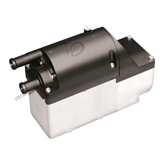
- Page 1 ® PH51W COOLANT HEATER Technical Description Installation Instructions Operating Instructions Troubleshooting and Parts...
-
Page 3: Table Of Contents
Table of Contents Introduction Heater Warnings Specifications Heater Components and Operating Concept Heater Kit List Heater Mounting Exhaust & Combustion Air Intake Connections Heater Plumbing Fuel System Electrical Connections Operating Switch Heater Operation Maintenance, Troubleshooting & Parts Heater Components... -
Page 4: Introduction
Introduction Thank you for purchasing our PH51W heater kit. The PH51W heater is designed to preheat your engine by using on-board diesel fuel and battery systems. Operation is simple and the heater provides a safe and reliable alternative to cold engine starting or need for electrical plug ins. -
Page 5: Heater Warnings
Heater Warnings Special Notes Note: Highlight areas requiring special attention or clarification. Caution Indicates that personal injury or damage to equipment may occur unless specific guidelines are followed. Warning Indicates that serious or fatal injury may result if specific guidelines are not followed. Warning - Asphyxiation Hazards Warning - Installation Hazards •... -
Page 6: Specifications
Specifications se note: Principal Dimensions er Dimensions Water inlet Fuel Water outlet supply line Combustion air Exhaust Performance Specifications Heating Medium Water / Ethylene Glycol Mixture Fuel Diesel Heating Output High – 4.2 KW (14,400 BTU) Low – 2.2 KW (7,500 BTU) Fuel Consumption High –... -
Page 7: Heater Components And Operating Concept
Main Components and Operating Concept Main parts of PH51W water heaters 1. Heat Exchanger 4. Glow Pin 2. Integrated Coolant Pump Assembly 5. Fuel Metering Pump 3. Combustion Air Blower Basic Operation of Heater • Fuel is delivered to the heater via the heater’s fuel pump. -
Page 8: Heater Kit List
Heater Kit List Part Number Description P51W-T801 Heater P65D-X302 Standard Operating Switch P65D-X301 Operating Switch-7 day Timer (option) P51W-X703 Heater Mounting Bracket P65W-X303 Wiring Harness 5M (16’) Power Harness, 20A Fuse 2.5M (9’) Fuel Pump Harness 5M (16’) Switch Harness, 5A Fuse 2.5M (8’) Remote Sensor Harness U65D-X508 Flexible Stainless-Steel Exhaust,... - Page 9 Heater Kit List P51W-X710 Installation Hardware U65D-X706 “L” Brackets U65D-X707 “Z” Mounting Bracket U65D-X502 26 – 28 mm Exhaust Clamp U65D-X701 28 mm “P” Routing Clamp Tek Mounting Screws M6 x 25 mm U65D-X521 11-25 mm hose clamp M6-1 x 25 Hex Head Screw M6-1 Hex Nuts 6mm Wave washers 6mm Flat Washer...
-
Page 10: Heater Mounting
Heater Mounting Mounting Considerations • Protect from road spray • Mount below engine coolant level to avoid air blockage. • Keep coolant hoses short to maximize flow and minimize heat loss. • Keep power wiring short to minimize voltage drop. •... -
Page 11: Exhaust & Combustion Air Intake Connections
Exhaust & Combustion Air Intake Connections The combustion air intake channels clean air into the heater. It can be eliminated if not required to ensure clean air intake. The exhaust tube channels exhaust safely away from the heater and vehicle. It also assists in providing a required amount of back pressure required to balance the combustion process. - Page 12 Exhaust & Combustion Air Intake Connections Exhaust emission pipe Combustion air input hose Exhaust tail pipe Max 1.5 m Min 0.2 m Max 2 m Warning - Fire Hazard The exhaust is hot, keep a minimum of 5 cm (2”) clearance from any heat sensitive material. Warning - Asphyxiation Hazards Route exhaust beyond the skirt of the cab and outside of the frame area.
-
Page 13: Heater Plumbing
Therefore, the technician must exercise professional judgment to achieve a safe and quality installation. It is important to try to optimize the coolant flow to get the best heat distribution and heater operation. Engine PH51W heater Radiator Heater core Engine cooling system Installation Procedure: •... - Page 14 Heater Plumbing Plumbing Guidelines: • Use 3/4” hoses to optimize coolant flow. • Keep the pick up and return points as far apart as possible. • Take coolant from a high pressure point of the engine (ie. back of block) •...
-
Page 15: Fuel System
Fuel System The PH51W fuel pump and fuel system are the heart of the heater. The fuel pump not only delivers fuel to the heater but also controls the amount of fuel delivered. The pump is designed to operate like an electric solenoid and works using electric pulses. - Page 16 Fuel System *Figure F3 *Figure F2 15 ° to vertical Fuel Pump Mounting • Using the bracket and rubber mount provided, install fuel pump as shown. (Figure F2) • Isolating the pump with the rubber holder helps to minimize noise created during operation. •...
- Page 17 Fuel System *Figure F5 *Figure F6 Ø22 mm (7/8”) 2 x 6mm (1/4”) 24mm (0.93”) Fuel Pick-Up Pipe Installation (Drill Option) • Drill mounting holes in tank to accommodate pick-up pipe as shown in Figure F4 • Drill the two (1/4”) holes first. (Figure F5) •...
-
Page 18: Electrical Connections
Electrical Connections Electrical System Installation • Route cables using either an existing cable passage or drill holes as required. • Seal the hole around the cables and make sure they are protected from chaffing and pinching. • Cut each harness section to length and install terminals and connectors as required. •... - Page 19 Electrical Connections PH51W Wiring Diagram Battery Main Fuse (12v = 20A, 24A = 15A) Switch Fuse 5A Control Switch Fuel Metering Pump Electronic Control Unit Combustion Air Blower Motor Glow Pin Flame Sensor Inlet Temperature Sensor Outlet Temperature Sensor Water Pump...
-
Page 20: Operating Switch
Route the switch harness from the heater to the Operating Switch and connect. Overview: The PHP Control Switch allows you to turn the heater on and off, regulate temperature, set operating mode, Parking Heater Products timed shutdown and timed start-up functions. It also facilitates troubleshooting by providing diagnostic 7 - Day Timer Operation Instructions codes. - Page 21 Time Single Programmed Start Down Multiple Programmed Starts Days On / Off Control: PHP Gen I Timer Instructions.doc Sept. 9, 2020 Press To start heater Displays and heater will begin start-up Heater will operate for 120 minutes or until switched off manually.
- Page 22 After 10 seconds without activity, current setting is saved. Press To adjust settings PHP Gen I Timer Instructions.doc Sept. 9, 2020 Remains displayed to indicate that program is activated and will operate the heater at the desired start time, once for 120 Minute run times.
- Page 23 Operating Switch Establishing Multiple Programmed Start Times 1. Press Two times Flashes 2. Press Once Flashes and shows Day, Hours, Mins, and d00 (d00 is the first Startup Selection, followed by d01, d02, etc). Settings for each Startup Selection d00, d01, d02, d03, etc. 3.
- Page 24 2. Once the timer switches the heater on through a programmed start time, it can only be switched off manually after one minute of run time. PHP Gen I Timer Instructions.doc 3. Once activated, Programmed Start Times will remain active and repeat weekly until they are Sept.
- Page 25 Remains displayed to indicate that program is allow program to exit. activated and will operate the heater until the set time. To Cancel Delayed Shutdown: Press Once Press Once to cancel delayed Disappears shutdown and stop heater PHP Gen I Timer Instructions.doc Sept. 9, 2020...
- Page 26 Operating Switch Self Diagnostics: will flash and an error code will be displayed If the heater’s controller detects a fault during operation, on the timer. If multiple faults are detected, they will circulate on the screen display. Fault Code Table Item Fault Code Indication The power supply voltage too high...
- Page 27 Displays Parameter Number and current value Press To toggle through the parameter settings Displays Parameter Number and changed value PHP Gen I Timer Instructions.doc Sept. 9, 2020 Press To adjust current settings Returns to previous display mode Press To save parameter setting changes and...
- Page 28 Whether to use wire control temperature Remote Sensor Connection as the environment temperature 0- Disabled 1- Enabled Initialize the timer parameters Initialize the timer parameters 0-don’t Initialize 1- Initialize Display Fahrenheit or Celsius 0-Display Celsius 1-Display Fahrenheit PHP Gen I Timer Instructions.doc Sept. 9, 2020...
-
Page 29: Heater Operation
Heater Operation Pre-Start • Check all fuel, electrical and plumbing connections. • Refill the engine coolant. • Bleed air from the coolant system & top up coolant. Start Up Upon signal from the operating switch, the heater conducts a sequenced start procedure. •... - Page 30 Heater Operation Safety Systems • ECU monitors operations through temperature sensor, overheat sensor and flame sensor. • Heater will shut down the heater in case of a malfunction. • ECU conducts circuit check on start up. • Heater will shut down after two consecutive, unsuccessful, 90 second attempts. •...
-
Page 31: Maintenance, Troubleshooting & Parts
Note: Batteries have significantly reduced capacity in cold weather Troubleshooting: The PH51W is equipped with self diagnostic capabilities. In the event of failure, an error code will be displayed on the operating switch. Refer to the Fault Code Diagnostic Chart for direction. In addition, consider our basic troubleshooting steps. - Page 32 Maintenance, Troubleshooting & Parts Fault Code Chart Error Code Fault description Remedy / Solution (Or Flashes) Over voltage cutout • Check vehicle charging system • Voltage must be less then 16v (32v) Under voltage cutout • Check voltage at heater during start up. •...
-
Page 33: Heater Components
Heater Components Heater assembly PH51W Heater Assembly... - Page 34 O Ring for Heat Exchanger, PHP, 5 kW Small Body, Coolant P51W-X112 Gasket for Heat Exchanger, PHP, 5 kW Small Body, Coolant P51W-T601 Water Pump with Housing, PHP, 5 kW Small Body, Coolant, 12 V P51W-F601 Water Pump with Housing, PHP, 5 kW Small Body, Coolant, 24 V P51W-X706...
- Page 38 ® Vancouver Toronto Dallas help@dksi.com 877-508-3900 DKSI.com PHP-122022-TM51W-REV01...
Need help?
Do you have a question about the PH51W and is the answer not in the manual?
Questions and answers