Table of Contents
Advertisement
Available languages
Available languages
Quick Links
Leggere attentamente le istruzioni prima di installare e utilizzare l'apparecchiatura.
Read the instructions carefully before installing and using the appliance.
Vor der Installation und Nutzung des Geräts müssen die Anleitungen aufmerksam durchgelesen werden.
Lire attentivement les instructions avant d'installer et d'utiliser l'appareil.
Léanse atentamente las instrucciones antes de instalar y utilizar el aparato.
Il mancato rispetto delle istruzioni fa decadere la garanzia del fabbricante.
In the event of failure to comply with the instructions, the manufacturer's warranty shall cease to apply.
Die Missachtung der Anleitungen hat den Verfall der vom Hersteller gewährten Garantie zur Folge.
Le non respect des instructions entraîne l'invalidation de la garantie du fabricant.
La inobservancia de las instrucciones provoca la invalidación de la garantía otorgada por el fabricante.
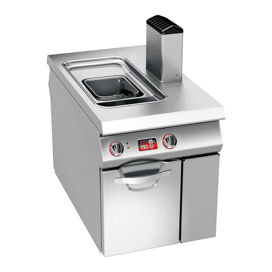
FRIGGITRICE GAS
GAS FRYER
GAS-FRITEUSE
FRITEUSE À GAZ
FREIDORA GAS
MANUALE D'USO E INSTALLAZIONE
USE AND INSTALLATION MANUAL
BEDIEN- UND INSTALLATIONSHANDBUCH
MANUEL D'UTILISATION ET D'INSTALLATION
MANUAL DE USO E INSTALACIÓN
06WFR3GD
10WFR4GD
Italiano
English
Deutsch
Français
Español
Rev.1
10/2017
3019702
IT
GB
DE
FR
ES
Advertisement
Chapters
Table of Contents

Related Manuals for Angelo Po 06WFR3GD


Summary of Contents for Angelo Po 06WFR3GD
- Page 1 Die Missachtung der Anleitungen hat den Verfall der vom Hersteller gewährten Garantie zur Folge. Le non respect des instructions entraîne l'invalidation de la garantie du fabricant. La inobservancia de las instrucciones provoca la invalidación de la garantía otorgada por el fabricante. FRIGGITRICE GAS GAS FRYER 06WFR3GD GAS-FRITEUSE 10WFR4GD FRITEUSE À GAZ FREIDORA GAS MANUALE D’USO E INSTALLAZIONE...
- Page 2 Cautela - Avvertenza Importante Non usare prodotti che contengono sostanze Verificare quotidianamente che i dispositivi dannose e pericolose per la salute delle per- di sicurezza siano perfettamente installati ed efficienti. sone (solventi, benzine, ecc.). Cautela - Avvertenza Cautela - Avvertenza La pavimentazione, in prossimità...
-
Page 3: Table Of Contents
Accessori a richiesta, 6 Accessori, dotazione, 6 Elettrovalvola gas, regolazione, 21 Accessori, installazione, 16 Alimentazione, trasformazione, 20 Filtraggio olio, 10 Allacciamento elettrico (06WFR3GD), 18 Fumi, allacciamento scarico, 20 Allacciamento elettrico (10WFR4GD), 19 Gas, allacciamento, 18 Allacciamento gas, 18 Gas, controllo pressione, 13... - Page 4 Sostituzione ugello spia pilota, 24 Regolazione aria primaria bruciatore, 23 Spegnimento e accensione bruciatori, 9 Regolazione elettrovalvola gas, 21 Spia pilota, sostituzione ugello, 24 Ricerca guasti, 13 Ripristino apparecchiatura, 11 Tabella segnalazione allarmi, 14 Trasformazione alimentazione, 20 Scarico fumi, allacciamento, 20 Trasporto, 15 Scopo del manuale, 3 Segnalazioni allarmi, tabella, 14...
-
Page 5: Informazioni Generali
INFORMAZIONI GENERALI ISTRUZIONI E AVVERTENZE PER IL LETTORE Per rintracciare facilmente gli argomenti specifici di parte: contiene tutte le informazioni ne- cessarie ai destinatari omogenei, cioè tutti gli interesse, consultare l’indice analitico posto all’ini- operatori esperti e autorizzati a movimentare, zio del manuale. -
Page 6: Informazioni Tecniche
MODALITÀ DI RICHIESTA ASSISTENZA Per qualsiasi esigenza rivolgersi alle agenzie Per ogni richiesta di assistenza tecnica, indicare i o alla sede centrale Angelo Po i cui riferimenti dati riportati sulla targhetta di identificazione ed il sono riportati nella sezione contatti del sito in- tipo di difetto riscontrato. - Page 7 DISPOSITIVI DI SICUREZZA Anche se l’apparecchiatura è completa di tutti i di- spositivi di sicurezza, in fase di installazione e allac- 06WFR3GD ciamento essi dovranno, se necessario, essere integrati con altri in modo da rispettare le leggi vi- genti in materia.
- Page 8 SEGNALI DI SICUREZZA E INFORMAZIONE L'illustrazione indica la posizione dei segnali appli- cati sull'apparecchiatura. A)Targa identificazione fabbricante e apparec- chiatura B)Pericolo generico: prima di effettuare qualsiasi tipo di intervento, leggere attentamente il manua- C)Pericolo generico: durante il lavaggio dell'appa- recchiatura non dirigere getti d'acqua in pressio- ne sulle parti interne.
-
Page 9: Sicurezza
SICUREZZA ISTRUZIONI E AVVERTENZE DI SICUREZZA Il fabbricante, in fase di progettazione e costruzio- vorati da tutti i fenomeni di contaminazione, è ne- ne, ha posto particolare attenzione agli aspetti che cessario pulire accuratamente gli elementi che possono provocare rischi alla sicurezza e alla salu- vengono a contatto direttamente o indirettamente te delle persone che interagiscono con l'apparec- con gli alimenti e tutte le zone limitrofe. -
Page 10: Uso E Funzionamento
USO E FUNZIONAMENTO ISTRUZIONI E AVVERTENZE PER L’USO E FUNZIONAMENTO Importante Gli utilizzatori, oltre ad essere autorizzati ed Prima dell’uso verificare che i dispositivi di opportunamente documentati, formati ed sicurezza siano perfettamente installati ed addestrati, se necessario, al primo uso, do- efficienti. - Page 11 ACCENSIONE E SPEGNIMENTO BRUCIATORI Per l'accensione e lo spegnimento procedere nel modo indicato per entrambi i bruciatori. Importante Prima dell'utilizzo effettuare un ciclo di cot- tura a vuoto ad una temperatura compresa fra 150 ÷ 165 °C. Accensione 1 - Aprire il rubinetto alimentazione gas . 2 - Ruotare la manopola (A) (pos.
- Page 12 AVVIAMENTO E ARRESTO CICLO COTTURA Per questa operazione procedere nel modo indicato. Avviamento 1 - Accendere i bruciatori (vedi pag. 9). 2 - Premere il tasto (A) e successivamente il tasto (B) per eseguire la fase di "melting" dell'olio. Quando viene raggiunta la temperatura di pre- riscaldamento si attiva il segnale acustico.
- Page 13 Importante Per identificare il termostato intervenuto, controllare quale bruciatore si è spento e agire sul pulsante corrispondente. 4 - Richiudere il portello (A). 06WFR3GD IDM-39611601100.tif INATTIVITÀ PROLUNGATA DELL’APPARECCHIATURA Se l'apparecchiatura rimane inattiva per un lungo perfici in acciaio inox; tempo, procedere nel modo indicato: 4 - eseguire tutte le operazioni di manuten- 1 - chiudere il rubinetto alimentazione gas;...
-
Page 14: Manutenzioni
– Sostituire l'olio quando produce fumo tra 160 ÷ LARE MINISTERO DELLA SANITÀ n. 1 deII'11 180 °C oppure quando assume un colorito scuro. gennaio 1991. – Usare periodicamente un polarimetro per misu- – Il massimo carico consigliato. per vasca, è di 1 rare la percentuale di composti polari (valore max consentito 25 g/100 g in conformità... -
Page 15: Guasti
PULIZIA VASCA, SUPPORTO CESTELLI E ACCESSORI Per questa operazione procedere nel modo indica- 1 - Spegnere e lasciare raffreddare l'apparecchia- tura (vedi pag. 9). 2 - Agire sull'interruttore sezionatore per disattiva- re l'alimentazione elettrica. 3 - Smontare il supporto cestelli (A) e pulirlo. 4 - Scaricare e filtrare l'olio (vedi pag. - Page 16 Importante Per qualsiasi esigenza rivolgersi alle agen- zie o alla sede centrale Angelo Po i cui rife- rimenti sono riportati nella sezione contatti del sito internet http://www.angelopo.com. Inconvenienti Cause Rimedi Fuga occasionale dovuta a Chiudere il rubinetto alimentazione Odore di gas.
-
Page 17: Movimentazione E Installazione
MOVIMENTAZIONE E INSTALLAZIONE ISTRUZIONI E AVVERTENZE PER LA MOVIMENTAZIONE E INSTALLAZIONE Importante Tutte le operazioni di movimentazione e di Colui che è autorizzato ad eseguire queste installazione dovranno essere eseguite nel operazioni dovrà, se necessario, organizza- rispetto della legislazione vigente in mate- re un “piano di sicurezza”... - Page 18 INSTALLAZIONE APPARECCHIATURA Tutte le fasi di installazione devono essere conside- rate sin dalla realizzazione del progetto generale. Prima di iniziare tali fasi, oltre alla definizione della zona di installazione, chi è autorizzato ad eseguire queste operazioni dovrà, se necessario, attuare un “piano di sicurezza”...
- Page 19 LIVELLAMENTO Agire sui piedi di appoggio (A) per livellare l'appa- recchiatura. IDM-39610800800.tif MONTAGGIO APPARECCHIATURE IN BATTERIA Per montare le apparecchia- ture in batteria (fianco a fian- co) procedere nel modo indicato. 1 - Sfilare le manopole (A). 2 - Svitare le viti (C) e smonta- re i cruscotti (B).
- Page 20 (aperto o chiuso). ALLACCIAMENTO ELETTRICO (06WFR3GD) Importante L'allacciamento deve essere effettuato da personale autorizzato e qualificato, nel ri- spetto delle leggi vigenti in materia e con...
- Page 21 Utilizzare un cavo con caratteristiche non infe- riori al tipo H05RN-F. Importante In fase di allacciamento fare attenzione al collegamento dei cavi di neutro e di terra; se non è effettuato correttamente il brucia- tore non si accende. 6 - Serrare il pressacavo (F). 7 - Rimontare il coperchio (D) e fissarlo con le viti (C) ad operazione ultimata.
- Page 22 ALLACCIAMENTO SCARICO FUMI 1 - Posizionare l'apparecchiatura sotto la cappa Importante (A) (vedi figura). Effettuare l’allacciamento nel rispetto delle Importante leggi vigenti in materia utilizzando il mate- riale appropriato e prescritto. L'accensione del ventilatore dell'impianto di aspirazione forzata deve comportare Allacciamento sotto cappa ad aspirazione forzata l'apertura automatica del rubinetto di ali- Per questa operazione procedere nel modo indicato.
-
Page 23: Regolazioni
COLLAUDO APPARECCHIATURA 3 - verificare la regolare accensione e combustio- Importante ne del bruciatore; 4 - verificare e, se necessario, regolare la pressio- Prima della messa in servizio, deve essere eseguito il collaudo dell'impianto, al fine di ne e la portata del gas al minimo e al massimo valutare le condizioni operative di ogni sin- (vedi pag. - Page 24 Eseguire questa operazione nel modo indicato su 7 - Accendere il bruciatore (vedi pag.9) e regolare entrambe le elettrovalvole gas. la vite (G) fino a leggere sul manometro la pres- sione indicata nella tabella iniettori in fondo al Metano manuale. 1 - Chiudere il rubinetto alimentazione gas 8 - Verificare la stabilità...
-
Page 25: Sostituzione Parti
REGOLAZIONE ARIA PRIMARIA BRUCIATORE Per questa operazione procedere nel modo indica- 8 - Richiudere il portello (A). 1 - Chiudere il rubinetto alimentazione gas . Distanza (D) Famiglia di gas 2 - Aprire il portello (A). (mm) 3 - Smontare la protezione (B). II (G 25/20-25mbar) 4 - Allentare la vite di bloccaggio (C). - Page 26 SOSTITUZIONE UGELLO BRUCIATORE IDM-39611602200.tif Per questa operazione procedere nel modo indica- 4 - Svitare l'ugello (C) e sostituirlo con quello adat- to al tipo di gas utilizzato (vedi tabella in fondo 1 - Chiudere il rubinetto alimentazione gas . al manuale). 2 - Aprire il portello (A).
- Page 28 Caution - warning Important Never use products containing substances Make a daily check that the safety devices harmful or hazardous for health (solvents, are properly installed and in good working order. Make a daily check that the safety petroleum spirits, etc.). devices are properly installed and in good working order.
- Page 29 Optional accessories, 6 Decommissioning the appliance, 24 Description of controls, 8 Packaging and unpacking, 15 Procedure for requesting service, 4 Electrical connection (06WFR3GD), 18 Purpose of the manual, 3 Electrical connection (10WFR4GD), 19 Replacement of the burner nozzle, 24 Faults, troubleshooting, 13...
- Page 30 Service, procedure for requesting, 4 Technical data, 5 Standard accessories, 6 Testing of the appliance, 21 Starting and stopping the cooking cycle, 10 Transport, 15 Switching the burner on and off, 9 Troubleshooting, 13 Table of alarm indications, 14 Unpacking and packaging, 15 - 2 - English...
-
Page 31: General Information
GENERAL INFORMATION INSTRUCTIONS AND WARNINGS FOR THE READER To find the specific topics of interest to you quickly, 2nd part: contains all the information neces- refer to the index at the start of the manual. sary for special categories of reader, i.e. all This manual is subdivided into two parts. -
Page 32: Technical Information
For all requirements contact the agents or the When requesting service, state the data provide on headquarters of Angelo Po which can be the nameplate and provide a description of the fault. found in the contacts section of the website ht- tp:// www.angelopo.com. - Page 33 SAFETY DEVICES Although the appliance is complete with all safety devices, during installation and connection addi- 06WFR3GD tional devices must be added if necessary to com- ply with the relevant legal requirements. The illustration shows the position of the devices...
- Page 34 SAFETY AND INFORMATION SIGNS The illustration shows the position of the signs fitted on the appliance. A)Nameplate with manufacturer and appliance data B)General hazard: read the manual carefully be- fore carrying out any procedure. C)General hazard: when washing the appliance do not point pressurised water jets at internal parts.
-
Page 35: Safety
SAFETY INSTRUCTIONS AND WARNINGS FOR SAFETY During design and construction, the manufacturer rounding zones must be cleaned thoroughly. For has paid special attention to factors which may cau- these operations, use only food-approved deter- se risks to the health and safety of the people inte- gents, and never use flammable products or pro- racting with the appliance. -
Page 36: Use And Operation
INSTRUCTIONS FOR USE INSTRUCTIONS AND WARNINGS FOR USE AND OPERATION Important Besides being authorised and appropriate- Before use, check that the safety devices ly documented, and if necessary,instructed are properly installed and in good working and trained, users,on first usage, have to order. - Page 37 SWITCHING THE BURNER ON AND OFF The lighting and turning off procedure is as de- scribed below for both burners. Important Before use, perform a cooking cycle with- out food at a temperature between 150 ÷ 165°C. Lighting 1 - Turn on the gas supply tap 2 - Turn the knob (A) clockwise (pos.
- Page 38 STARTING AND STOPPING THE COOKING CYCLE To carry out this operation, proceed as follows. Starting 1 - Light the burners (see page 9) 2 - Press key (A) and then key (B) to activate the oil "melting" procedure. When the preheating temperature is reached the beeper sounds.
- Page 39 To identify the thermostat that has been tripped, check which burner has cut out and press the corresponding button. 4 - Close the hatch (A). 06WFR3GD IDM-39611601100.tif LENGTHY DOWNTIMES OF APPLIANCE If the appliance is to be out of use for a lengthy pe- 3 - Spread a film of edible oil over the stain- riod, proceed as follows.
-
Page 40: Servicing
– Change the oil when it fumes between 160 ÷ – The recommended batch load is 1 Kg for single 180°C or when it becomes dark in colour. well. – Use a polarimeter regularly to measure the per- centage of polarised compounds. SERVICING INSTRUCTIONS AND WARNINGS FOR SERVICING Keep the appliance at peak efficiency by carrying... -
Page 41: Fault
CLEANING THE WELL, BASKET SUPPORT AND ACCESSORIES To carry out this operation, proceed as follows. 1 - Switch the appliance off and leave it to cool (see page 9). 2 - Turn off the circuit-breaker to disconnect it from the electrical mains. 3 - Remove the basket support (A) and clean it. - Page 42 Important For all requirements contact the agents or the headquarters of Angelo Po which can be found in the contacts section of the web- site http://www.angelopo.com. Inconvenienti Cause Rimedi Occasional leak because Turn off the gas supply tap and Smell of gas.
-
Page 43: Handling And Installation
HANDLING AND INSTALLATION INSTRUCTIONS AND WARNINGS FOR HANDLING AND INSTALLATION Important All handling and installation operations If necessary, the person authorised to carry should be carried out in accordance with out these operations must organise a "safe- current legislation on health and safety at ty plan"... - Page 44 INSTALLATION OF THE APPLIANCE All installation stages must be considered right from production of the general layout. Before starting these stages, as well as deciding the place of instal- lation, if necessary, the person authorised to carry out these operations must organise a "safety plan" to protect the people directly involved, and he must also ensure strict compliance with all legal requirements, especially those relating to mobile work-sites.
- Page 45 LEVELLING Adjust the floor-mounted feet (A) to level the appli- ance. IDM-39610800800.tif ASSEMBLY APPLIANCES IN BANKS To assemble appliances in banks (side by side) proceed as described below. 1 - Pull off the knob (A). 2 - Undo the screws (C) and remove the control pan- els (B).
- Page 46 (on or off) must be obvious at a glance. ELECTRICAL CONNECTION (06WFR3GD) Important The connection must be made by author- ised, skilled personnel, in accordance with the relevant legal requirements, using ap- propriate and specified materials.
- Page 47 Important When connecting, take care over the con- nection of the neutral and earth wires; if they are not connected correctly, the burn- er does not light. 6 - Tighten the cable gland (F). 7 - Replace the lid (D) and fix it with the screws (C) on completion of the operation.
- Page 48 CONNECTION OF FUME EXHAUST VENT Important Important Make the connection in compliance with The gas supply tap must open automatical- ly when the fan of the extraction system is the relevant legal requirements, using ap- switched on. propriate and recommended materials. Connecting to a fan extractor hood To carry out this operation, proceed as follows.
-
Page 49: Adjustment
TESTING OF THE APPLIANCE 3 - Check that the burner is switching on correctly Important and its combustion. 4 - Check the gas pressure and flow-rate at mini- Before it is put into service, the system must be tested to check the operating conditions mum and maximum settings and adjust if nec- of every single component and identify any essary (see page 13). - Page 50 Carry out this operation as described on both the 6 - Turn the gas supply tap back on. gas solenoid valves. 7 - Light the burner (see page 9) and turn the screw (G) until the pressure gauge shows the Natural gas pressure recommended in the table of injectors 1 - Turn off the gas supply tap.
-
Page 51: Replacing Parts
ADJUSTING BURNER PRIMARY AIR To carry out this operation, proceed as follows. 8 - Close the hatch (A). 1 - Turn off the gas supply tap 2 - Open the hatch (A). Distance (D) Gas family 3 - Remove the guard (B). (mm) 4 - Undo the locking screw (C). - Page 52 REPLACEMENT OF THE BURNER NOZZLE IDM-39611602200.tif To carry out this operation, proceed as follows. 4 - Unscrew the nozzle (C) and replace it with the 1 - Turn off the gas supply tap one suitable for the type of gas in use (see table 2 - Open the hatch (A).
- Page 54 Vorsicht – Achtung Wichtig Verwenden Sie keine Produkte, die Stoff e en- Stellen Sie jeden Tag durch Kontrollen si- thalten, welche für die menschliche Gesun- cher, dass die Sicherheitsvorrichtungen fa- chgerecht installiert sind und einwandfrei dheit schädlich gefährlich sind funktionieren. (Lösemittel, Benzin, usw.).
- Page 55 INHALTSVERZEICHNIS Ref. Kapitel Seite 1 ALLGEMEINES..............3 2 TECHNISCHE INFORMATIONEN........4 3 SICHERHEIT ..............7 1. TEIL 4 GEBRAUCH UND BETRIEB..........8 5 WARTUNG............... 12 6 DEFEKTE................. 13 7 HANDHABUNG UND INSTALLATION ......15 8 EINSTELLUNGEN ............21 2. TEIL 9 USTAUSCH VON BAUTEILE ..........
- Page 56 Umstellung der Gasversorgung, 20 Sicherheitsvorrichtungen, 5 Verpackung und Auspacken, 15 Starten und Stoppen des Garzyklus, 10 Zubehörausstattung, 6 Stromanschluss (06WFR3GD), 18 Zweck des Handbuchs, 3 Stromanschluss (10WFR4GD), 19 Tabelle der Fehlermeldungen, 14 Technische Daten, 5 Testlauf zur Abnahme des Geräts, 21 Transport, 15 Typenschild für Hersteller und Gerät, 3...
-
Page 57: Allgemeines
ALLGEMEINES ANWEISUNGEN UND WARNHINWEISE FÜR DEN LESER Konsultieren Sie das Sachregister, das am Anfang des 2. Teil: Diese Informationen wenden sich an eine Handbuchs zu finden ist, um leichter unter bestimmten bestimmte Zielgruppe. Sie sind für erfahrene Be- Themen von besonderem Interesse nachschlagen zu diener bestimmt, die für Handhabung, Transport, können. -
Page 58: Technische Informationen
Geben Sie bei jedem Kontakt mit dem Kunden- Handelsvertretungen oder den Hauptsitz des dienstzentrum nicht nur den aufgetretenen Scha- Unternehmens Angelo Po, die entsprechenden den, sondern auch die Daten an, die auf dem Kontaktdaten sind auf der Webseite http:// Typenschild angeführt sind. - Page 59 Siehe Tabellen und "Anschlussschema" am Ende des Handbuchs. SICHERHEITSVORRICHTUNGEN Das Gerät wird zwar mit sämtlichen planmäßigen Sicherheitsvorrichtungen geliefert, es kann jedoch 06WFR3GD notwendig sein, während Installation und An- schluss ggf. weitere ergänzende Maßnahmen zu ergreifen, um den Anforderungen der einschlägi- gen geltenden Gesetze zu entsprechen.
- Page 60 SICHERHEITSHINWEISE UND INFORMATIONEN Die Abbildung zeigt die Anordnung der aufgekleb- ten Sicherheitshinweise auf das Gerät. A)Typenschild mit Angabe des Herstellers und der Gerätekenndaten B)Allgemeine Gefahr: Vor Ausführung irgendei- nes Eingriffs zuerst das Handbuch aufmerksam lesen. C)Allgemeine Gefahr: Beim Waschen des Geräts den Wasserstrahl nicht direkt auf die inneren Tei- le richten.
-
Page 61: Sicherheit
SICHERHEIT ANWEISUNGEN UND WARNHINWEISE FÜR DIE SICHERHEIT Der Hersteller hat bei Entwicklung und Fertigung die- den Nahrungsmitteln in Berührung kommen sowie ses Produkts besondere Sorgfalt auf Aspekte verwen- die angrenzenden Zonen, akkurat gereinigt wer- det, die eine Gefahr für die Sicherheit und die den. -
Page 62: Gebrauch Und Betrieb
GEBRAUCH UND BETRIEB ANWEISUNGEN UND WARNHINWEISE FÜR DIE GEBRAUCH UND BETRIEB Wichtig Die Anwender müssen nicht nur befugt und an- die vorgesehenen Leistungen zu erhalten. gemessen informiert, ausgebildet und geschult Überprüfen Sie vor dem Gebrauch, ob die Sicher- sein sondern ggf. auch beim ersten Einsatz des heitsvorrichtungen installiert sind und einwand- Gerätes bestimmte Handgriffe simulieren, um frei funktionieren. - Page 63 EIN- UND AUSSCHALTEN DES BRENNERS Verfahren Sie zum Zünden und Abschalten der bei- den Brenner folgendermaßen: Wichtig Vor dem Gebrauch einen Leer-Garzyklus bei einer Temperatur zwischen 150 ÷ 165°C vornehmen. Zündung 1 - Öffnen Sie den Gashahn 2 - Drehen Sie den Schalter (A) (Pos. 1), um die Stromversorgung einzuschalten.
- Page 64 STARTEN UND STOPPEN DES GARZYKLUS Für diesen Vorgang in der angegebenen Weise verfahren. Starten 1 - Die Brenner einschalten (siehe S. 9). 2 - Die Taste (A) und dann die Taste (B) drücken, um die "Melting"-Phase für das Öl vorzuneh- men.
- Page 65 Zum Identifizieren des ausgelösten Ther- mostaten kontrollieren, welcher Brenner sich ausgeschaltet hat, und die entspre- chende Taste drücken. 4 - Schließen Sie die Klappe (A). 06WFR3GD IDM-39611601100.tif LÄNGERER STILLSTAND DES GERÄTS Verfahren Sie folgendermaßen, falls das Gerät län- mittelöl auf die Edelstahlflächen auf.
-
Page 66: Wartung
– Das Korbaufhängergestell zum Abtropfen des – Das Öl auswechseln, wenn es zwischen i 160 ÷ Frittierguts benutzen. 180 °C Rauch produziert oder wenn es eine – Wird die Benutzung des Geräts für kurze Zeit un- dunkle Farbe annimmt. terbrochen, die Öltemperatur niedriger schalten –... -
Page 67: Defekte
REINIGUNG DES BECKENS, DES KORBGESTELLS UND DES ZUBEHÖRS Für diesen Vorgang in der angegebenen Weise verfahren. 1 - Das Gerät (siehe S. 9) ausschalten und abküh- len lassen. 2 - Mit dem Trennschalter die Stromzufuhr unter- brechen. 3 - Das Korbgestell (A) ausbauen und reinigen. 4 - Das Öl ablassen und filtrieren (siehe S. - Page 68 Wichtig Bei Rückfragen wenden Sie sich bitte an die Han- delsvertretungen oder den Hauptsitz des Unter- nehmens Angelo entsprechenden Kontaktdaten sind auf der Webseite http:// www.angelopo.com unter „Kontakt“ zu finden. Probleme Ursachen Lösungen Beim Löschen der Flamme Schließen Sie den Gashahn und Gasgeruch.
-
Page 69: Handhabung Und Installation
HANDHABUNG UND INSTALLATION ANWEISUNGEN UND WARNHINWEISE FÜR DIE INSTALLATION UND HANDHABUNG Wichtig Beachten Sie die Hinweise des Herstellers, Die für diese Operationen autorisierte Person die direkt auf der Verpackung, auf dem Gerät wird bei Bedarf einen "Sicherheitsplan" auf- selbst oder in der Gebrauchsanweisung zu stellen müssen, um die Unversehrtheit der finden sind, wenn Sie das Gerät handhaben direkt an dem Vorgang beteiligten Personen... - Page 70 INSTALLATION DES GERÄTS Es müssen sämtliche Phasen der Installation, schon von der Umsetzung des allgemeinen Projekts an, berücksichtigt werden. Die für diese Operationen au- torisierte Person wird vor Einleitung dieser Phasen den Installationsstandort bestimmen und bei Bedarf einen "Sicherheitsplan" aufstellen, um die Unver- sehrtheit der direkt am Vorgang beteiligten Personen zu gewährleisten und die gesetzlichen Bestimmun- gen zu befolgen.
- Page 71 NIVELLIEREN Regulieren Sie die Füße (A), um das Gerät wasser- waagengerecht aufzustellen. IDM-39610800800.tif MONTAGE BEI REIHENAUFSTELLUNG Verfahren Sie folgenderma- ßen, um Geräte (nebeneinan- der) einer Reihe aufzustellen. 1 - Den Schalter (A) abziehen. 2 - Die Schrauben (C) aus- schrauben und die Blen- den (B) ausbauen.
- Page 72 Er muss in einer leicht zugänglichen Position installiert werden und sein Zustand (offen oder ge- schlossen) muss sofort erkennbar sein. STROMANSCHLUSS (06WFR3GD) Wichtig Der Anschluss muss von autorisiertem Fach- personal in Einklang mit den einschlägigen gesetzlichen Bestimmungen und unter Ver- wendung von geeignetem und vorschrifts- mäßigem Material ausgeführt werden.
- Page 73 Wichtig Bei der Ausführung des Anschlusses auf den Anschluss des Neutral- und des Schutzleiters achten. Wenn diese An- schlüsse nicht richtig ausgeführt werden, kann der Brenner nicht gezündet werden. 6 - Die Zugentlastung (F) festziehen. 7 - Abschließend den Deckel (D) wieder anbringen und mit den Schrauben (C) befestigen.
- Page 74 ANSCHLUSS DES RAUCHABZUGS Wichtig Den Anschluss in Einklang mit den einschlä- 1 - Das Gerät unter der Haube (A) positionieren. gigen gesetzlichen Bestimmungen und unter Wichtig Verwendung des hierfür geeigneten und vor- geschriebenen Materials ausführen. Die Einschaltung des Ventilators der Ab- sauganlage musst das automatische Öff- Anschluss unter...
-
Page 75: Einstellungen
TESTLAUF ZUR ABNAHME DES GERÄTS 3 - Sicherstellen, dass Zündung und Verbrennung Wichtig beim Brenner ordnungsgemäß funktionieren. 4 - Überprüfen Sie Gasdruck und –durchsatz bei mi- Vor der Inbetriebnahme muss ein Testlauf der Anlage durchgeführt werden, um den nimaler und maximaler Zufuhr und regulieren Sie, Betriebszustand jeder einzelnen Kompo- falls notwendig, die Einstellungen (siehe S. - Page 76 Diesen Vorgang in der angegebenen Weise bei bei- 6 - Öffnen Sie den Gashahn wieder. den Gasmagnetventilen ausführen. 7 - Den Brenner zünden (siehe S.9) und die Schraube (G) regeln, bis am Druckmesser der Methan Wert in der Düsentabelle (am Ende des Hand- 1 - Schließen Sie den Gaszufuhrhahn.
- Page 77 EINSTELLUNG DER PRIMÄRLUFT DES BRENNERS Für diesen Vorgang in der angegebenen Weise 8 - Schließen Sie die Klappe (A). verfahren. 1 - Schließen Sie den Gaszufuhrhahn Abstand (D) Gasfamilie 2 - Öffnen Sie die Klappe (A). (mm) 3 - Die Schutzabdeckung (B) entfernen. II (G 25/20-25mbar) 4 - Die Klemmschraube (C) lockern.
- Page 78 AUSWECHSELN DER BRENNERDÜSE IDM-39611602200.tif Für diesen Vorgang in der angegebenen Weise 4 - Schrauben Sie die Düse (C) heraus und erset- verfahren. zen Sie sie mit dem für den betreffenden Gas- typ geeigneten Ersatzteil (siehe Tabelle am 1 - Schließen Sie den Gaszufuhrhahn Ende des Handbuches).
- Page 80 Attention Important Ne pas utiliser de produits qui contiennent Vérifier quotidiennement que les disposi- des substances dangereuses pour la santé tifs de sécurité soient parfaitement instal- lés et efficaces. des personnes (solvants, essences, etc.). Attention Attention Le sol, à proximité de l’appareil, pourrait être Avant toute intervention, couper l’alimenta- glissant.
- Page 81 Appareils en batterie, montage, 17 nement, 8 Assistance, demande, 4 Instructions et avertissements pour l’utilisation, 11 Instructions et avertissements pour l’entretien, 12 Branchement électrique (06WFR3GD), 18 Instructions et avertissements pour la manutention et l’ins- Branchement électrique (10WFR4GD), 19 tallation, 15 But du manuel, 3 Instructions et avertissements pour les réglages, 21...
- Page 82 Sécurité, dispositifs de, 5 Pannes, dépannage, 13 Signalisations des alarmes, tableau, 14 Pression du gaz, contrôle, 13 Signaux de sécurité et information, 6 Raccordement du gaz, 18 Tableau signalisations des alarmes, 14 Raccordement évacuation des fumées, 20 Transformation de l’alimentation, 20 Réglage air primaire du brûleur, 23 Transport, 15 Réglage de l’électrovalve du gaz, 21...
- Page 83 INFORMATIONS GENERALES INSTRUCTIONS ET AVERTISSEMENTS POUR LE LECTEUR Pour retrouver facilement les sujets qui vous inté- 2e partie: elle contient toutes les informa- ressent, consulter l’index analytique au début du tions nécessaires aux destinataires homogè- manuel. nes, c’est-à-dire tous les opérateurs experts Ce manuel est divisé...
- Page 84 DEMANDE D’ASSISTANCE Pour toute exigence, s’adresser aux agences Pour toute demande d’assistance technique, indi- ou au siège centra Angelo Po dont les référen- quer les données reportées sur la plaque d’identifi- ces sont reportées dans la section contacts du cation et le type de défaut relevé.
- Page 85 DISPOSITIFS DE SÉCURITÉ Même si l’appareil est complet de tous les disposi- tifs de sécurité, lors de l’installation et du raccorde- 06WFR3GD ment, ils devront, si nécessaire, être intégrés avec d’autres pour respecter les lois en vigueur. L’illustration indique la position des dispositifs A)Robinet d’alimentation du gaz: pour ouvrir et...
- Page 86 SIGNAUX DE SÉCURITÉ ET INFORMATION L’illustration indique la position des signaux appli- qués sur l'appareil A)Plaque d'identification du fabricant et de l'ap- pareil B)Danger générique: avant tout type d’interven- tion, lire attentivement ce manuel. C)Risque générique: pendant le lavage de l’appa- reil ne pas diriger de jets d’eau sous pression sur les pièces intérieures.
- Page 87 SÉCURITÉ INSTRUCTIONS ET MISES EN GARDE POUR LA SÉCURITÉ Le fabricant, lors de la conception et de la fabrica- Pour maintenir l’hygiène et protéger les aliments de tion, a fait très attention aux aspects qui peuvent tous les phénomènes de contamination, il faut net- provoquer des risques à...
- Page 88 UTILISATION ET FONCTIONNEMENT INSTRUCTIONS ET AVERTISSEMENTS POUR L'UTILISATION ET FONCTIONNEMENT Important Les utilisateurs, en plus d’être autorisés et Avant l’utilisation, vérifier si les dispositifs documentés de façon appropriée, formés et de sécurité sont parfaitement installés et entraînés, si nécessaire, lors de la première efficaces.
- Page 89 ALLUMAGE ET EXTINCTION DU BRULEUR Pour l’allumage et l’extinction des brûleurs, procé- der comme suit pour les deux brûleurs. Important Avant l'utilisation effectuer un cycle de cuisson à vide à une température comprise entre 150 ÷ 165°C. Allumage 1 - Ouvrir le robinet d’alimentation du gaz 2 - Tourner la manette (A) (pos.
- Page 90 MISE EN MARCHE ET ARRÊT DU CYCLE DE CUISSON Pour cette opération, procéder comme suit. Mise en marche 1 - Allumer les brûleurs (voir page 9). 2 - Presser la touche (A) puis la touche (B) pour ef- fectuer la phase de "melting" de l'huile. Quand la température de préchauffage est atteinte, le signal sonore se met en marche.
- Page 91 Pour identifier le thermostat qui est interve- nu, voir quel brûleur s’est éteint et agir sur le bouton correspondant. 4 - Refermer la porte (A). 06WFR3GD IDM-39611601100.tif INUTILISATION PROLONGÉE DE L’APPAREIL Si l'appareil reste inactif pendant longtemps, procé- 3 - Étaler un voile d’huile alimentaire sur les der comme suit.
- Page 92 – Quand on interrompt l’utilisation de l’appareil – Remplacer l’huile si elle produit de la fumée entre pour une brève période, réduire la température 160 ÷ 180° C ou lorsqu’elle devient foncée. de l’huile au minimum ou éteindre pour éviter des –...
- Page 93 NETTOYAGE DE LA CUVE, DU SUPPORT DES PANIERS ET DES ACCESSOIRES Pour cette opération, procéder comme suit. 1 - Eteindre et laisser refroidir l’appareil (voir page 9). 2 - Agir sur l’interrupteur sectionneur pour désacti- ver l’alimentation électrique. 3 - Démonter le support paniers (A) et le nettoyer. 4 - Vider et filtrer l’huile (voir page 10).
- Page 94 Important Pour toute exigence, s’adresser aux agen- ces ou au siège centra Angelo Po dont les références sont reportées dans la section contacts du site internet http://www.ange- lopo.com. Inconvénients Causes Solutions Fuite occasionnelle due à Fermer le robinet d’alimentation Odeur de gaz.
- Page 95 MANUTENTION ET INSTALLATION INSTRUCTIONS ET AVERTISSEMENTS POUR LA MANUTENTION ET L’INSTALLATION Important Effectuer la manutention et l’installation en Celui qui est autorisé à effectuer ces opéra- respectant les informations fournies par le tions devra, si nécessaire, organiser un fabricant, reportées directement sur l’em- “plan de sécurité”...
- Page 96 MISE EN PLACE DE L’APPAREIL Toutes les phases de mise en place doivent être prises en considération, dès la réalisation du projet général. Avant de commencer ces phases, outre la définition de la zone de mise en place, celui qui est autorisé...
- Page 97 MISE À NIVEAU Agir sur les pieds d’appui (A) pour mettre de niveau l’appareil. IDM-39610800800.tif MONTAGE DES APPAREILS EN BATTERIE Pour monter les appareils en batterie (les uns à côté des autres), procéder comme suit. 1 - Enlever la manette (A). 2 - Dévisser les vis (C) et démonter les tableaux de commandes (B).
- Page 98 état (ouvert ou fermé). BRANCHEMENT ÉLECTRIQUE (06WFR3GD) Important Le branchement doit être fait par du per- sonnel autorisé et qualifié, conformément aux lois en vigueur à ce sujet en utilisant le matériel approprié...
- Page 99 Important Au moment du branchement, faire attention à la connexion des câbles de neutre et de terre ; si elle n'est pas effectuée correcte- ment, le brûleur ne s'allume pas. 6 - Serrer le collier (F). 7 - Remonter le couvercle (D) et revisser les vis (C) lorsque l’opération est terminée.
- Page 100 RACCORDEMENT ÉVACUATION DES FUMÉES 1 - Positionner l’appareil sous la hotte (A). Important Important Effectuer le raccordement conformément aux lois en vigueur à ce sujet en utilisant le L’allumage du ventilateur du système d’as- matériel approprié et prescrit. piration forcée doit entraîner l’ouverture automatique du robinet d’alimentation gaz.
- Page 101 ESSAI DE L’APPAREIL 3 - Vérifier l'allumage régulier et la combustion du Important brûleur. 4 - Vérifier et, si nécessaire, régler la pression et le Avant la mise en service, l’essai de l’instal- lation doit être fait pour évaluer les condi- débit du gaz au minimum et au maximum (voir tions opérationnelles...
- Page 102 Effectuer cette opération sur les deux électrovalves nis sur demande). du gaz, comme indiqué. 6 - Rouvrir le robinet d’alimentation du gaz 7 - Allumer le brûleur (voir page 9) et régler la vis Méthane (G) jusqu'à lire sur le manomètre la pression re- 1 - Fermer le robinet d’alimentation du gaz.
- Page 103 RÉGLAGE AIR PRIMAIRE DU BRÛLEUR Pour cette opération, procéder comme suit. 8 - Refermer la porte (A). 1 - Fermer le robinet d’alimentation du gaz 2 - Ouvrir la porte (A). Distance (D) Famille de gaz 3 - Démonter la protection (B). (mm) 4 - Desserrer la vis de blocage (C).
- Page 104 REMPLACEMENT DE LA BUSE DU BRULEUR IDM-39611602200.tif Pour cette opération, procéder comme suit. 4 - Dévisser la buse (C) et la remplacer par celle 1 - Fermer le robinet d’alimentation du gaz adaptée au type de gaz utilisé (voir tableau à la 2 - Ouvrir la porte (A).
- Page 106 Precaución - advertencia Important No usar productos que contengan sustan- Controlar periódicamente que los equipos cias nocivas y/o peligrosas para la salud de de seguridad se encuentren en perfecto es- tado y estén correctamente instalados. las personas (disolventes, bencinas, etc.). Precaución - advertencia Precaución - advertencia El pavimento, cerca del equipo, podría ser...
- Page 107 Búsqueda de averías, 13 Identificación fabricante y equipo, 3 Conexión a la salida de humos, 20 Instalación de accesorios, 16 Conexión eléctrica (06WFR3GD), 18 Instalación del equipo, 16 Conexión eléctrica (10WFR4GD), 19 Instrucciones y advertencias para el lector, 3 Control de la presión del gas, 13...
- Page 108 Nivelación, 17 Seguridad, dispositivos de, 5 Señalización de las alarmas, tabla de, 14 Objetivo del manual, 3 Señalizaciones de seguridad e información, 6 Sustitución inyector quemador, 24 Período prolongado de inactividad del equipo, 11 Sustitución inyector testigo piloto, 24 Presión del gas, control de la, 13 Prueba de funcionamiento del equipo, 21 Tabla de señalización de las alarmas, 14 Puesta en marcha y detención del ciclo de cocción, 10...
-
Page 109: Informaciones De Carácter General
INFORMACIONES DE CARÁCTER GENERAL INSTRUCCIONES Y ADVERTENCIAS PARA EL LECTOR Para ubicar fácilmente los temas específicos de inte- 2a parte: contiene todas las informaciones ne- rés, consúltese el índice analítico que se encuentra al cesarias para destinatarios homogéneos, esto inicio del manual. es, todos los operadores expertos y autorizados Este manual comprende dos partes. -
Page 110: Informaciones De Carácter Técnico
MODALIDAD PARA REQUERIR ASISTENCIA Para cualquier necesidad, diríjase a las agen- Para solicitar asistencia técnica deberán indicarse cias o a la sede central de Angelo Po, cuyos los datos reproducidos en la placa de identificación referentes se indican en la sección de contac- y el tipo de desperfecto que se ha verificado. - Page 111 DISPOSITIVOS DE SEGURIDAD Aunque el equipo cuente con todos los dispositivos de seguridad, en los casos en que así lo determi- 06WFR3GD nen las leyes vigentes en materia, se deberá com- plementar con otros dispositivos en las fases de instalación y enlace.
- Page 112 SEÑALIZACIONES DE SEGURIDAD E INFORMACIÓN La ilustración indica la posición de las señalizacio- nes fijadas en el equipo. A)Placa de identificación fabricante y aparato B)Peligro genérico: antes de efectuar cualquier tipo de intervención léase atentamente el ma- nual. C)Peligro genérico: durante el lavado del aparato no dirigir chorros de agua a presión hacia sus partes internas.
-
Page 113: Seguridad
SEGURIDAD INSTRUCCIONES Y ADVERTENCIAS PARA LA SEGURIDAD Durante las fases de diseño y producción el fabricante taminación, es necesario limpiar prolijamente los ha prestado especial atención a los factores que pue- elementos que entran en contacto directa o indirec- den provocar riesgos en cuanto a seguridad y salud tamente con los alimentos y las zonas aledañas. -
Page 114: Uso Y Funcionamiento
USO Y FUNCIONAMIENTO INSTRUCCIONES Y ADVERTENCIAS PARA EL USO Y FUNCIONAMIENTO Important Los utilizadores, además de estar autori- Antes del uso, controlar que los dispositi- zados y oportunamente documentados, vos de seguridad estén instalados de for- formados y adiestrados, si fuera necesa- ma correcta y eficaz. - Page 115 ENCENDIDO Y APAGADO DEL QUEMADOR Para el encendido y el apagado, efectuar en ambos quemadores las siguientes operaciones. Important Antes del uso efectúe un ciclo de cocción en vacío a una temperatura comprendida entre 150 ÷ 165 °C. Encendido 1 - Abrir el grifo de alimentación del gas 2 - Girar el mando (A) (pos.
- Page 116 PUESTA EN MARCHA Y DETENCIÓN DEL CICLO DE COCCIÓN Para efectuar esta operación, aplicar las siguientes instrucciones. Puesta en marcha 1 - Encienda los quemadores (véase pág. 9). 2 - Presione la tecla (A) y a continuación la tecla (B) para activar la fase de "melting" del aceite. Al alcanzarse la temperatura de precalenta- miento se activa el aviso sonoro.
- Page 117 4 - Cierre la portezuela (A). 06WFR3GD IDM-39611601100.tif PERÍODO PROLONGADO DE INACTIVIDAD DEL EQUIPO En caso de que el equipo deba permanecer inacti- ble una capa delgada de aceite comestible.
-
Page 118: Mantenimiento
– Sustituya el aceite cuando produzca humo entre 160 – La carga máxima recomendada es de 1 kilogra- ÷ 180 °C, o bien cuando adquiera un color oscuro. mos por cuba. – Usar periódicamente un polarímetro para medir el porcentaje de compuestos polares. MANTENIMIENTO INSTRUCCIONES Y ADVERTENCIAS PARA EL MANTENIMIENTO Mantener el equipo en condiciones de máximo ren-... -
Page 119: Averías
LIMPIEZA DE CUBA, SOPORTE CESTOS Y ACCESORIOS Para efectuar esta operación, aplicar las siguientes instrucciones. 1 - Apague y deje enfriar el aparato (véase pág. 2 - Opere con el interruptor aislador para interrum- pir la alimentación eléctrica. 3 - Desmontar el soporte cestos (A) y limpiarlo. 4 - Descargue y filtre el aceite (véase pág. - Page 120 Important Para cualquier necesidad, diríjase a las agencias o a la sede central de Angelo Po, cuyos referentes se indican en la sección de contactos del sitio web http://www.ange- lopo.com. Inconvenientes Causas Remedios Fuga ocasional debida al Cerrar el grifo de alimentación del Olor de gas.
-
Page 121: Desplazamiento E Instalación
DESPLAZAMIENTO E INSTALACIÓN INSTRUCCIONES Y ADVERTENCIAS PARA EL DESPLAZAMIENTO Y LA INSTALACIÓN Important Todas las operaciones de movimiento e La persona autorizada para efectuar estas instalación tendrán que realizarse respe- operaciones deberá, si fuera necesario, or- tando la legislación vigente en materia de ganizar un "plan de seguridad", a fin de sal- salud y seguridad en el trabajo. - Page 122 INSTALACIÓN DEL EQUIPO Durante la realización del proyecto general, deben ser consideradas todas las fases de la instalación. Antes de comenzar dichas fases, además de esta- blecer la zona de instalación, la persona autorizada a efectuar estas operaciones deberá, si fuera nece- sario, aplicar un "plan de seguridad"...
- Page 123 NIVELACIÓN Operar con las patas de apoyo (A) para nivelar el equipo. IDM-39610800800.tif MONTAJE DE EQUIPOS EN BATERÍA Para montar los equipos en batería (uno al lado del otro) aplicar las siguientes instruc- ciones. 1 - Retire el mando (A). 2 - Desenroscar los tornillos (C) y desmontar los pa- neles de mando (B).
- Page 124 (abierto o cerrado). CONEXIÓN ELÉCTRICA (06WFR3GD) Important La conexión deberá asignarse al personal autorizado y experto, que deberá respetar...
- Page 125 Utilizar un cable con características no inferio- res a aquél de tipo H05RN-F. Important Durante las operaciones de enlace se debe- rá prestar especial atención a la conexión de los cables de neutro y de tierra ya que, en caso de no ser correctamente efectuada, el quemador no se encenderá.
- Page 126 CONEXIÓN A LA SALIDA DE HUMOS 1 - Colocar el aparato debajo de la campana (A) Important (véase figura). Lleve a cabo la conexión respetando las leyes Important vigentes en materia y utilice siempre el mate- rial adecuado y previsto por el constructor. El ventilador de la instalación de aspiración forzada deberá...
-
Page 127: Regulaciones
PRUEBA DE FUNCIONAMIENTO DEL EQUIPO 3 - Controle el correcto encendido y combustión Important del quemador. 4 - Controlar y, si fuera necesario, regular la pre- Antes de la puesta en servicio debe efec- tuarse la prueba de funcionamiento del sis- sión y el caudal del gas al mínimo y al máximo tema, a fin de evaluar las condiciones (véase pág. - Page 128 Ejecute esta operación de la manera indicada, pro- 6 - Vuelva a abrir la llave de alimentación del gas. cediendo respecto de ambas electroválvulas gas. 7 - Encienda el quemador (véase pág. 9) y opere con el tornillo (G) hasta obtener que el manóme- Metano tro indique la presión conforme con las indicacio- 1 - Cerrar el grifo de alimentación del gas.
- Page 129 REGULACIÓN AIRE PRIMARIO QUEMADOR Para efectuar esta operación, aplicar las siguientes 8 - Cierre la portezuela (A). instrucciones. 1 - Cerrar el grifo de alimentación del gas Distancia (D) Familia gas 2 - Abra la portezuela (A). (mm) 3 - Desmontar la protección (B). II (G 25/20-25mbar) 4 - Afloje el tornillo de fijación (C).
- Page 130 SUSTITUCIÓN INYECTOR QUEMADOR IDM-39611602200.tif Para efectuar esta operación, aplicar las siguientes 4 - Desenrosque el inyector (C) y cámbielo por instrucciones. otro que sea adecuado para el tipo de gas utili- 1 - Cerrar el grifo de alimentación del gas. zado (véase tabla al final del manual).
- Page 131 /h 1,32 m /h 0,79 Kg/h 0,78 Kg/h 06WFR3GD N. 2 10/11 1,16 m /h 1,35 m 30W/220V 1~N. /60Hz SCHEDA ALLACCIAMENTI (06WFR3GD) - CONNECTION CARD (06WFR3GD) - ANSCHLUSSSCHEMA (06WFR3GD) - FICHE DES RACCORDEMENTS (06WFR3GD) - FICHA DE ENLACES (06WFR3GD) IDM-39611602402.tif...
- Page 132 Bruciatori Consumo gas Allacciamento elettrico Burner - Brenner Gas consumption - Gasverbrauch Modello Electrical connection Consommation de gaz - Consumo de gas Bruleur - Quemadores Model - Modelle Stromanschluss Modèle - Modelo Branchement électrique 5,5 kW G25.3 Conexión eléctrica G25.1 10WFR4GD N.
- Page 133 SCHEMA ELETTRICO (06WFR3GD) - ELECTRIC DIAGRAM (06WFR3GD) - SCHALTBILD (06WFR3GD) - SCHÉMA ÈLECTRIQUE (06WFR3GD) - ESQUEMA ELÉCTRICO (06WFR3GD) 06WFR3GD 230V/1N 220V/1N IDM-39611602700.tif 1)Morsettiera - Terminal board - Klemmenleiste - Bornier - Tablero scher Anzünder - Allumeur électronique - Encendedor electrónico...
- Page 134 SCHEMA ELETTRICO (10WFR4GD) - ELECTRIC DIAGRAM (10WFR4GD) - SCHALTBILD (10WFR4GD) - SCHÉMA ÈLECTRIQUE (10WFR4GD) - ESQUEMA ELÉCTRICO (10WFR4GD) 10WFR4GD 230V/1N 220V/1N IDM-39611602600.tif 1) Morsettiera - Terminal board - Klemmenleiste - Bornier - Tablero de bornes 12) Interruttore (vasca destra) - Switch (right well) - Schalter (rechte Wanne) - In- 2) Interruttore (vasca sinistra) - Switch (left well) - Schalter (linke Wanne) - Inter- terrupteur (cuve droite) - Interruptor (cuba derecha) rupteur (cuve gauche) - Interruptor (cuba izquierda)
- Page 135 Tabella iniettori bruciatore (06WFR3GD) - Burner injector table - Tabelle der Brennerdüsen Tableau des injecteurs des brûleurs - Tabla inyectores quemador pen mbar Qn max kW p (3) mbar ø (4) ø (5) ø (6) Qn min kW p (7) mbar ø...
- Page 136 Tabella iniettori bruciatore (06WFR3GD) - Burner injector table - Tabelle der Brennerdüsen Tableau des injecteurs des brûleurs - Tabla inyectores quemador pen mbar Qn max kW p (3) mbar ø (4) ø (5) ø (6) Qn min kW p (7) mbar ø...
- Page 137 Tabella iniettori bruciatore (06WFR3GD) - Burner injector table - Tabelle der Brennerdüsen Tableau des injecteurs des brûleurs - Tabla inyectores quemador pen mbar Qn max kW p (3) mbar ø (4) ø (5) ø (6) Qn min kW p (7) mbar ø...
- Page 138 Tabella iniettori bruciatore (10WFR4GD) - Burner injector table - Tabelle der Brennerdüsen Tableau des injecteurs des brûleurs - Tabla inyectores quemador pen mbar Qn max kW p (3) mbar ø (4) ø (5) ø (6) Qn min kW p (7) mbar ø...
- Page 139 Tabella iniettori bruciatore (10WFR4GD) - Burner injector table - Tabelle der Brennerdüsen Tableau des injecteurs des brûleurs - Tabla inyectores quemador pen mbar Qn max kW p (3) mbar ø (4) ø (5) ø (6) Qn min kW p (7) mbar ø...
- Page 140 Tabella iniettori bruciatore (10WFR4GD) - Burner injector table - Tabelle der Brennerdüsen Tableau des injecteurs des brûleurs - Tabla inyectores quemador pen mbar Qn max kW p (3) mbar ø (4) ø (5) ø (6) Qn min kW p (7) mbar ø...
- Page 141 Tabella caratteristiche gas - Table of gas characteristics - Tabelle der Gas-Eigenschaften Tableau des caractéristiques du gaz - Tabla características gas Potere calorifero inferiore (Hi) Famiglia Tipo di gas Indice Wobbe (MJ/m Net calorific value (Hi) Group Gas type Wobbe index (MJ/m Unterer Heizwert (Hi) Familie Gastypen...
- Page 142 Angelo Po Grandi Cucine S.p.A. con socio unico - Sede Centrale s.s. Romana Sud 90/F - 41012 Carpi (Mo) - Italy Tel: +39 059 639411 Fax: +39 059 642499 www.angelopo.com IT - È vietata la riproduzione, anche parziale, di questo documento senza il consenso del fabbricante. Egli è impegnato in una politica di continuo mi- glioramento e si riserva il diritto di modifi care questa documentazione senza l’obbligo di preavviso purché...
Need help?
Do you have a question about the 06WFR3GD and is the answer not in the manual?
Questions and answers