Table of Contents
Advertisement
Quick Links
Advertisement
Table of Contents

Related Manuals for Angelo Po 0G1FR3GD


Summary of Contents for Angelo Po 0G1FR3GD
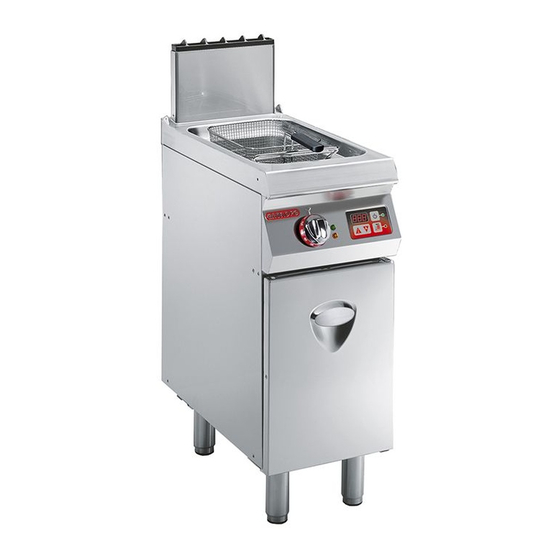
- Page 1 0G1FR3GD GAS FRYER USE AND INSTALLATION MANUAL 3016690...
- Page 2 Contact for Sales or Service: Angelo Po Catering Equipment Unit 4, 15-17 Heatherdale Road. Ringwood, Victoria 3134. Telephone: (03) 9874 0440 Facsimile: (03) 9874 0330...
-
Page 3: Table Of Contents
CONTENTS ref. chapters page 0 INFORMATION FOR THE READER ........2 1 GENERAL INFORMATION ..........2 2 TECHNICAL INFORMATION ..........3 3 SAFETY ................5 PART 4 USE AND OPERATION ............6 5 SERVICING ..............10 6 FAULT ................11 7 HANDLING AND INSTALLATION........ -
Page 4: Constructor And Appliance Identification
INFORMATION FOR THE READER To find the specific topics of interest to you quickly, re- part: contains all the information necessary fer to the index at the start of the manual. for special categories of reader, i.e. all skilled op- This manual is subdivided into two parts. -
Page 5: Appliance, General Description
) Voltage. ) Power. ) Frequency. 10) Test voltage indicator frame. PROCEDURE FOR REQUESTING SERVICE Contact one of the authorised service centres for all When requesting service, state the data provide on requirements. the nameplate and provide a description of the fault. TECHNICAL INFORMATION GENERAL DESCRIPTION OF THE APPLIANCE The fryer, referred to from now on as the appliance, is... -
Page 6: Accessories, Standard
TECHNICAL DATA See tables and "Connection chart" at the back of the manual. SAFETY DEVICES Although the appliance is complete with all safety de- vices, during installation and connection additional devices must be added if necessary to comply with the relevant legal requirements. The illustration shows the position of the devices. -
Page 7: Safety
OPTIONAL ACCESSORIES The appliance can be equipped with the following ac- cessories on request. A)Type B11 tall fume exhaust vent. B)Type B11 tall flue with draught damper device. C)Oil filter. D)Oil drain container. E)Gas conversion kit. F) Set of baskets (KCFR12). IDM-3960331050_1.tif SAFETY SAFETY REGULATIONS... -
Page 8: Controls, Description
USE AND OPERATION RECOMMENDATIONS FOR USE Important The rate of accidents deriving from the use of Use only as intended by the constructor and appliances depends on many factors which never tamper with any device to obtain per- cannot always be foreseen and controlled. formance levels outside the rated specifica- Some accidents may be caused by unpredict- tions. -
Page 9: Burner, Switching On And Off
ture. function). disables the beeper when in use. )Temperature maintenance light: lights up to in- dicate that the temperature maintenance function )Preheating button: activates and deactivates the function which has been activated and the appliance is waiting to maintains the temperature at 100°C (melting start the cooking cycle. -
Page 10: Cooking, Starting And Stopping
STARTING AND STOPPING COOKING To start and stop the appliance, proceed as follows. Starting 1 - Light the burners (see page 7). 2 - Press key (A) and then key (B) to activate the oil "melting" procedure. N.B.: when the preheating temperature is reached the beeper sounds;... -
Page 11: Appliance, Lengthy Downtimes
RESETTING THE APPLIANCE If the safety thermostat is tripped, the appliance has to be restored to the initial working conditions as follows. 1 - Allow the oil to cool to 30-40°C. 2 - Open the hatch (A). 3 - Press the button (B) of the safety thermostat to re- store the gas supply. -
Page 12: Cleaning, Recommendations For
SERVICING RECOMMENDATIONS FOR SERVICING Keep the appliance at peak efficiency by carrying out necessary, clean: the well (see page 11); the scheduled servicing procedures recommended the burner (see page 10); by the constructor. Proper servicing will allow the best the appliance and the surrounding environment performance, a longer working life and constant (see page 10). -
Page 13: C Checking Gas Pressure
CLEANING THE WELL To carry out this operation, proceed as follows. 1 - Switch the appliance off and leave it to cool (see page 7). 2 - Turn off the circuit-breaker to disconnect it from the electrical mains. 3 - Remove the basket support structure (A). 4 - Drain and filter the oil (see page 8). -
Page 14: Alarms, Indications Table
Fault Causes Remedies Occasional leak because flame Turn off the gas supply tap and Smell of gas. has gone out. ventilate the room. Check that the ignition devices are in good working order. Light by hand with a naked light. The spark ignition devices are not working. -
Page 15: Handling And Installation
HANDLING AND INSTALLATION RECOMMENDATIONS FOR HANDLING AND INSTALLATION Important When handling and installing the appliance If necessary, the person authorised to carry comply with the information provided by the out these operations must organise a "safe- constructor directly on the packaging, on ty plan"... -
Page 16: Appliance, Installation
INSTALLATION OF THE APPLIANCE All installation stages must be considered right from pro- duction of the general layout. Before starting these stag- es, as well as deciding the place of installation, if necessary, the person authorised to carry out these oper- ations must organise a "safety plan"... -
Page 17: Flue Deflector, Installation
INSTALLATION OF THE FLUE DEFLECTOR 1 - Insert the pivots (1) and (2) both in the holes FIG.A of the deflector (5) and in the upper holes of the flue (8) (see Fig.A). 2 - Fix the pivots (1) and (2) by means of nuts (6) and washer (7). -
Page 18: Connection, Electrical
GAS CONNECTION To make the connection, connect the mains line to the appliance's connection pipe, fitting a shut-off tap (A), to allow the gas supply to be cut off when necessary. Important The tap (A), not supplied with the appliance, must be installed in an easily accessible position and its status (on or off) must be obvious at a glance... -
Page 19: Conversion Of Gas Supply
CONVERSION OF THE GAS SUPPLY The constructor has tested the appliance with its own mains gas, identified by the sticker applied to the nameplate. If the type of gas to be connected is different from that used for testing, proceed as follows. 1 - Turn off the gas supply tap (A). -
Page 20: Adjusting Gas Solenoid Valve
TESTING OF THE APPLIANCE sary (see page 16); Important 3 - check that the burner is switching on correctly and its combustion; Before it is put into service, the system must 4 - check the gas pressure and flow-rate at minimum be tested to check the operating conditions and maximum settings and adjust if necessary of every single component and identify any... -
Page 21: Adjusting Burner Primary Air
Natural gas 1 - Turn off the gas supply tap. 2 - Open the hatch (A). 3 - Undo the pressure connection screw (B). 4 - Connect the pressure gauge (C) to the pressure test point. 5 - Unscrew the cap (D) and if necessary fit the spring (F) and adjuster screw (E) (supplied on request). -
Page 22: Appliance, Decommissioning
REPLACING PARTS RECOMMENDATIONS FOR REPLACING PARTS Before carrying out any replacement procedure, acti- The manufacturer declines all responsibly for injury or vate all the safety devices provided and decide damage to components due to the use of non original whether staff at work and those in the vicinity should parts, or extraordinary work on the appliance which be informed. -
Page 23: Annexes
- ANNEXES - Burner Total gas consumption Model Electrical connection 22 MJ/h ULPG 0G1FR3GD N. 2 44 MJ/H 44 MJ/h 240V 1~N. 50Hz 30 W - CONNECTION CARD - IDM-39603619800.tif... - Page 24 - ELECTRIC DIAGRAM - 240V/1N IDM-39603624000.tif 1) Terminal block 6) Electronic ignition 2) Switch 7) Electronic thermostat controller 3) Mains power indicator light 8) Temperature display 4) Thermostat indicator light 9) Safety thermostat 5) Gas solenoid valve with ignition contact 10) Thermocouple N.G.C.
Need help?
Do you have a question about the 0G1FR3GD and is the answer not in the manual?
Questions and answers