Table of Contents
Advertisement
Quick Links
Introduction
®
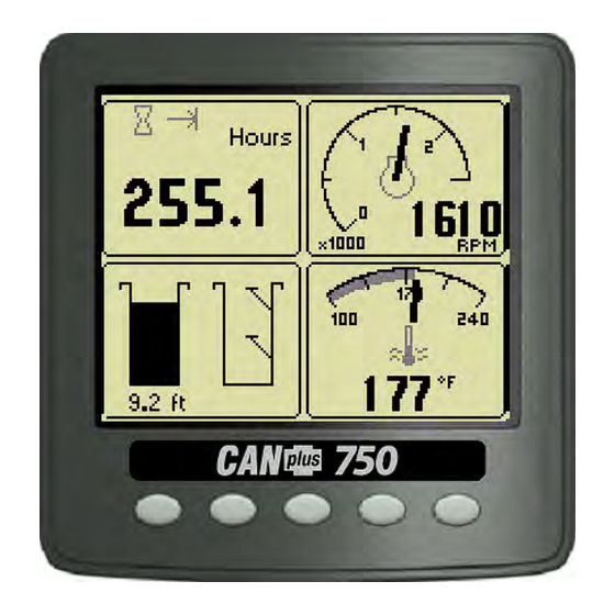
The CANplus
750 (CP750™) control panel is a universal
platform to monitor, control and automatically start/stop
both electronically and mechanically governed diesel
engines. The microprocessor-based, solid-state design uses
high power semiconductors instead of outdated
electromechanical relays to ensure reliable high current
switching. Graphical gauge pages or a single large analog
gauge are displayed on the 4.25" diagonal LCD. Virtually
any SAE J1939 parameter reported by the ECU (Engine
Control Unit) can be displayed including RPM, coolant
temperature, oil pressure, engine hours, voltage and
diagnostic codes. An analog fuel level input broadcasts the
fuel level across the CANbus to the display and other J1939
devices. The trans-reflective, backlit display is clearly
readable in both bright sunlight as well as total darkness
and is housed in a rugged IP67 rated housing.
Current alarm conditions are displayed in plain language on popup messages and can be viewed in the
alarm list. Various diagnostic screens allow detailed investigation of the CANbus data stream. By accessing
the Configuration Menu, users can customize displayed data to show metric or US units, display language
and various other parameters such as the full-scale reading of gauges. Four bright LEDs below the display
indicate Auto Standby, Preheat, Stop and Warning status.
Button 1
Analog Gauge
Pages
Repeated presses
cycle through four
cycle through four
pages of analog
gauges (16 total).
gauges (16 total).
463-3000-08 Initial - 18-Feb-2008
CANplus and CANplus logo are registered trademarks of LOFA Industries, Inc.
CP750 and the LOFA logo are trademarks of LOFA Industries, Inc.
™
Operation and Troubleshooting
Button 2
Digital Gauge
Pages
Repeated presses
Repeated presses
pages of digital
available analog
®
750 Control Panel
Five buttons access a context dependent button bar when
any button from 1 to 4 is pressed. The graphical menu
structure uses easily understood icons to indicate the
button's current function. After 5 seconds of inactivity the
button bar disappears.
Button 3
Button 4
Single Analog
Active Alarm
Gauge
Displays active
cycle through
alarms including a
plain language
gauges.
Button 5
Page
Configures the
parameters
displayed by gauge
description.
Gauge
Adjust
pages.
1
Advertisement
Table of Contents
Troubleshooting

Related Manuals for Lofa CANplus 750


Summary of Contents for Lofa CANplus 750
- Page 1 (16 total). gauges (16 total). gauges. description. pages. 463-3000-08 Initial - 18-Feb-2008 CANplus and CANplus logo are registered trademarks of LOFA Industries, Inc. CP750 and the LOFA logo are trademarks of LOFA Industries, Inc.
-
Page 2: Automatic Operation
Remote monitoring can alert maintenance requirements, operational problems, improper operation and location with geo-fence alert. The Web-browser interface allows monitoring an entire fleet of equipment in a central location. Contact LOFA Industries for more information. 463-3000-08 Initial - 18-Feb-2008... -
Page 3: Important Safety Information
CANplus Actuator Kit. Only single speed operation is possible with a mechanical throttle. Warning! When replacement parts are required, LOFA Industries recommends using replacement parts supplied by LOFA or parts with equivalent specifications. Failure to heed this warning could lead to premature failure, product damage, personal injury or death. -
Page 4: Manual Operation
Users can attempt to rectify the fault by restoring factory defaults (see Configuration Menu for details). Contact LOFA Industries for assistance if the fault persists. After the start-up screen is cleared, the display shows readings on its virtual gauges. -
Page 5: Automatic Start/Stop Operation
750 Control Panel Operation and Troubleshooting ® Two-State Throttle The optional Two-State Throttle uses a two position rocker switch to adjust the requested engine speed. Pressing the rabbit icon requests the engine to go to Run RPM. Pressing the turtle icon requests the engine to go to Idle RPM. - Page 6 750 Control Panel Operation and Troubleshooting ® will return to the previous speed until the stop condition exists. Automatic Start/Stop Warning! When the key is turned to the autostart position and a start condition exists, the panel will start immediately! Always configure parameters by turning the key to run.
- Page 7 750 Control Panel Operation and Troubleshooting ® Maintain Functions The Maintain In and Maintain Out functions adjust the engine speed to keep the transducer level at the Target Set Point. The Servo Gain adjusts how aggressively the throttle is adjusted while the Servo Delay controls how often the throttle is adjusted.
- Page 8 750 Control Panel Operation and Troubleshooting ® CANplus Display Soft buttons simplify the user interface by displaying a button bar above the buttons when any of the first 4 buttons (buttons 1 to 4, starting from the left) are pressed. Icons on the button bar change to represent the current function of each button.
-
Page 9: Single Analog Gauge
750 Control Panel Operation and Troubleshooting ® Adjust Mode can be disabled in the Configuration Menu to prevent accidental changes. Digital Gauge Pages Digital Gauge Pages display the same data as the Analog Gauge Pages but in digital only format. To enable Digital Gauge Pages, press any of the first 4 buttons to show the top level button bar and then press button 2 . -
Page 10: Alarm List
750 Control Panel Operation and Troubleshooting ® Number/Failure Mode Indicator) pair defined by the SAE J1939 standard. Additionally, if enabled, the beeper sounds as an audible cue. Example alarm message, alarm list screens showing unacknowledged conditions and acknowledged alarms. After acknowledgement, the exit button becomes active. -
Page 11: Configuration Menu
Configurator is a Windows PC program and a hardware adapter that allows total access to the parameters of the panel. For more information about the CANplus Configurator, please contact LOFA. Configuration Menu This Configuration Menu allows the user to set various operating parameters such as US or metric units, scale limits for tachometer and service timers. -
Page 12: Display Menu
750 Control Panel Operation and Troubleshooting ® Display Menu The Display Menu allows the user to configure items affecting how information is displayed. Language Menu Units Menu This menu allows the user to choose between This menu allows the user to set the units used for English, Swedish, French, German, Spanish, speed, distance, pressure, volume and Italian, Dutch and Portuguese. - Page 13 750 Control Panel Operation and Troubleshooting ® Gauges Menu Service This menu allows the user to configure aspects of Sets the sixteen (16) service intervals in hours and the gauges displayed. Button 3 selects the resets the service timer. Setting the service interval previous value while Button 4 selects the next to 0 disables the timer and the word Off is...
-
Page 14: System Menu
750 Control Panel Operation and Troubleshooting ® System Menu The System Menu allows the user to configure items affecting how the system functions. . Button 4 cycles through the available values for the selected item. The default settings are: Demo Setting Metric The display supports several demo modes to... - Page 15 750 Control Panel Operation and Troubleshooting ® Com Viewer J1939 Settings Displays CANbus data received and engine This screen allows adjustments specific to the configuration transmitted by the ECU. J1939 data link. Engine Source J1939 Viewer This screen provides a hexadecimal dump of the Selects which source the display listens to for messages received on the CANbus.
- Page 16 750 Control Panel Operation and Troubleshooting ® Note Button 1 adjusts the first digit of the PIN. Button 2 adjusts the second digit, button 3 Consult your engine supplier to establish the the third digit and button 4 the fourth appropriate SPN conversion method version.
- Page 17 PART No Unit part number will not be accessible. VERS Software version number Clearing the PIN requires returning the Flash memory checksum display to LOFA for service. SOURCE The source of received data LIB1 Low level system library version LIB2...
- Page 18 750 Control Panel Operation and Troubleshooting ® Autostart Menu This submenu allows the user to configure automatic start/stop operation. Refer to Automatic Start/Stop Operation for more information. Idle RPM Mode Selects the RPM the control system will request for This menu selects the basic automatic start/stop idle speed.
- Page 19 750 Control Panel Operation and Troubleshooting ® Ramp to Run s Intermediate RPM Selects the number of seconds to ramp from Selects the RPM the control system will request for intermediate speed to run speed after intermediate speed. The intermediate speed can intermediate warm-up be used to prime pump or charge lines during automatic start/stop operation.
- Page 20 750 Control Panel Operation and Troubleshooting ® Range Starter Selects appropriate range for the transducer type This submenu configures starter control options for autostart High Set Point For Empty and Maintain Out modes, sets the level that begins an autostart cycle. For Fill and Maintain In modes sets the level that ends the cycle.
-
Page 21: Settings Menu
750 Control Panel Operation and Troubleshooting ® Settings Menu This submenu allows the user to configure CANplus hardware. Warning Governor Incorrectly configuring the CP750 CAN Address Selects between Elect (electronically governed) prevents the display from receiving I/O Board and Mech (mechanically governed) engines data for the display menus and can result in data modes. - Page 22 The output is prestart alarm Prestart activated 10 seconds before the engine automatically starts Note The Aux Output is available on a connector in the I/O Board only. Changing the prestart alarm time requires using the LOFA Configurator. 463-3000-08 Initial - 18-Feb-2008...
-
Page 23: Telemetry Menu
750 Control Panel Operation and Troubleshooting ® Telemetry Menu This menu allows configuring the optional telemetry system. Status Telem J1939 Address Displays telemetry and modem status information Defines address the telemetry module is using for retrieved from the telemetry module: CANbus communications. -
Page 24: Service Required
750 Control Panel Operation and Troubleshooting ® Db Viewer The Database Viewer displays and decodes all data monitored by the display. This diagnostic tool allows viewing data not normally displayed. The list can be scrolled using buttons 1 and 2 and closed by pressing Button 5 Note The Database Viewer is always in English regardless of language selected. -
Page 25: Adjusting Lighting And Contrast
750 Control Panel Operation and Troubleshooting ® Data Communications Failure The data communications failure popup icon flashes if the display does not detect data. The warning disappears and normal operation resumes once data is detected. Note Incorrectly configuring the Engine Source address will result in no data available for display. Data Not Available Gauges and the Db Viewer will display if the desired data is not available. - Page 26 750 Control Panel Operation and Troubleshooting ® Indicators Auto Standby LED (Green) A solidly illuminated Auto Standby LED indicates the keyswitch is in the auto start position and the system is ready to start. Preheat LED (Amber) A solidly illuminated Preheat LED indicates the engine is preheating. When the LED extinguishes, the preheat period is complete and the engine may be cranked.
-
Page 27: Typical J1939 Wiring Topology
750 Control Panel Operation and Troubleshooting ® Typical J1939 Wiring Topology Most electronically governed engine installations include a harness with built in J1939 backbone. Use twisted shielded pair with a drain wire for CANbus wiring terminated with 120Ωresistors at each end. The maximum length for the bus is 131 feet (40 m) and stubs should not exceed 39 inches (1m) in length. -
Page 28: Unsealed Connectors
These chemicals may cause seal damage and allow water entry. Use LOFA provided cavity plugs to seal the connector if wires are removed. Unsealed Connectors For unsealed connectors exposed to the elements, LOFA recommends using dielectric grease to protect contacts. Warning LOFA does not recommend using sealant with unsealed connectors. -
Page 29: Battery Circuit Requirements
A reliable dedicated power circuit must be provided for the control system. LOFA recommends the power connection be made directly to the battery. Grounding through frame members is not recommended! All circuit paths must be capable of carrying any likely fault currents without damage. -
Page 30: Suppression Of Voltage Transients (Spikes)
Warning The installation of voltage transient suppression at the transient source is required. LOFA follows SAE recommended electrical environment practices. Inductive devices such as relays, solenoids and motors generate voltage transients and noise in electrical circuits. Unsuppressed voltage transients can exceed SAE specifications and damage electronic controls. -
Page 31: Welding On Equipment With Electronic Controls
750 Control Panel Operation and Troubleshooting ® Welding on Equipment with Electronic Controls Proper welding procedures are required to avoid damage to electronic controls, sensors and associated components. The component should be removed for welding if possible. The following procedure must be followed if the component must be welded while installed on equipment with electronic controls. -
Page 32: General Troubleshooting
750 Control Panel Operation and Troubleshooting ® General Troubleshooting For additional information, refer to engine manufacturer troubleshooting guide. No response from starter motor Possible Cause Possible Remedy No battery voltage to starter Verify wiring and battery connection (power and ground) Battery discharged Charge or replace battery, verify alternator charging Tripped overcurrent protection... -
Page 33: Engine Troubleshooting
750 Control Panel Operation and Troubleshooting ® Engine Troubleshooting Note Most problems with ECU controlled engines can be pinpointed via the ECU diagnostic messages. Use the display or ECU diagnostic tool to view fault codes. All engine state information and diagnostic codes shown by the CANplus display are provided by the CANbus. -
Page 34: Control System Troubleshooting
750 Control Panel Operation and Troubleshooting ® Control System Troubleshooting Control system does not perform self test Possible Cause Possible Remedy Tripped overcurrent protection Correct fault, replace or reset overcurrent protection Faulty connection to battery Correct battery connections (see Battery Circuit Requirements) Faulty control system Repair or replace control system Control system performs normal self test, engine cranks, runs and shuts down... -
Page 35: Testing A Warning Or Shutdown
750 Control Panel Operation and Troubleshooting ® Testing a Warning or Shutdown Shutdown simulation with ECU controlled engines requires using the ECU diagnostic tool. Refer to the diagnostic tool documentation to simulate a warning or shutdown. Testing CANbus Most information provided to the CANplus display is sent by the ECU via the CANbus. CANbus is an international data bus used to support SAE J1939. -
Page 36: Diagnostic Trouble Codes (Dtc)
750 Control Panel Operation and Troubleshooting ® Diagnostic Trouble Codes (DTC) CANbus Diagnostic Trouble Codes are a pair of numbers; the Suspect Parameter Number (SPN) and Failure Mode Identifier (FMI). The SPN indicates the faulting subsystem and the FMI identifies the type of failure. Typical SPNs Standard SPN codes are defined by SAE J1939-71. - Page 37 750 Control Panel Operation and Troubleshooting ® Data Parameters Monitored This table lists the engine and transmission parameters that are monitored via the CANbus. The parameters can be displayed by the user-configurable gauge pages or the single analog gauge. DB is an abbreviation for the internal database which stores all data transmitted from the engine/transmission.
- Page 38 750 Control Panel Operation and Troubleshooting ® Icon Parameter Gauge Pages Single Gauge Database Turbo Oil Temperature Intake Manifold Temperature Air Inlet Temperature Exhaust Temperature Auxiliary Temperature 1 ...
-
Page 39: Software Revision History
750 Control Panel Operation and Troubleshooting ® Glossary Controller Area Network (also referred to as CANbus); serial communications protocol for electronic engines use Diagnostic Trouble Code; the combination of SPN and FMI that identifies a specific error Engine Control Unit; electronic device responsible for controlling and monitoring engine operation Engine Control Module;... - Page 40 Automatic Start/Stop Warning! When the key is turned to the autostart position and a start condition exists, the panel will start immediately! Always use lock out/tag out procedures when servicing autostart equipment! 463-3000-08 Initial - 18-Feb-2008...
Need help?
Do you have a question about the CANplus 750 and is the answer not in the manual?
Questions and answers