
Related Manuals for Lofa CANplus 1000


Summary of Contents for Lofa CANplus 1000
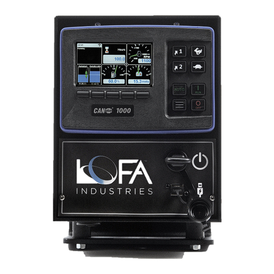
- Page 1 ® CANplus 1000 Control Panel Operation Manual December 2019 LOFA Document No. 463-3002-59...
- Page 2 Disclaimer: The contents of this document are not to be used for advertising, publication, or promotional purposes. Citation of trade names does not constitute an official endorsement or approval of the use of such commercial products. All product names and trademarks cited are the property of their respective owners. DESTROY THIS DOCUMENT WHEN NO LONGER NEEDED.
-
Page 3: Table Of Contents
Stopping the Engine ..................22 Autostart Operation.................... 23 Prerequisites....................23 Enabling Autostart..................23 Autostart Menu.................... 23 Behavior ....................24 ................24 6.4.1 Configuring Operation .............. 24 6.4.2 Configuring Start and Stop Events Page ii LOFA document No. 463-3002-59 Page ii... - Page 4 Timed Run ....................32 Configuration ....................33 Display Menu ....................33 ® ® LOFA CANplus Customizer Software Suite and LOFA CANplus Config Kit ... 33 ® LOFA CANplus Customizer Software Suite and a USB drive ....... 34 Firmware Update ....................35 Updating via USB drive .................
- Page 5 This page has been intentionally left blank.
-
Page 6: Important Safety And Emissions Information
LOFA products are not designed or approved for use as critical components of any safety device or system that is intended to prevent bodily injury, protect life, or prevent property damage. - Page 7 LOFA panel applicability, machine guarding, general safety guidelines, labeling, and warnings. The installer of this LOFA panel and/or LOFA harness is responsible for the correct sizing and integration of a suitable fuse/breaker on the un-switched DC circuit supplying power to the LOFA panel.
-
Page 8: Auxiliary Engine Stop Disclaimer
ECU initiated emissions event. LOFA document No. 463-3002-59 Page 3... -
Page 9: Overview
2. Overview 2 Overview The LOFA CP1000 control panel is a manual and autostart platform for EPA Tier 3, EPA Tier 4 (interim), EPA Tier 4, and EU Stage V electronically governed diesel or natural gas engines. It can also can control mechanically governed diesel engines. Graphical quad-gauge pages are displayed on the 4.3-inch diagonal WQVGA (480x272 pixels) LCD. -
Page 10: Display
ECU, including RPM, engine temperature, oil pressure, and diagnostic codes. It can be easily configured to customer preference, including gauge type (analog or digital), gauge arrangements, gauge size, units, and language. Different software versions may have slightly different displays. LOFA document No. 463-3002-59 Page 5... -
Page 11: Button Bar
Pages, press any of the first four (4) buttons to show the top level button bar and then press button 1 to cycle through the pages. The current page is indicated by the number in the center of the screen. Page 6 LOFA document No. 463-3002-59 Page 6... -
Page 12: Status And Autostart Gauge
The Status gauge shows the status of many of the emissions-related features as well as date, time, signal strength. The Autostart gauge shows the start and stop events or levels on the left and the maintain/cruise control level on the right. 3.4 Autostart and Throttling Dashboards 3.4.1 Autostart LOFA document No. 463-3002-59 Page 7... -
Page 13: Throttling
When the Dashboard-1 button is pressed again, the display will revert back to the gauge page. 3.4.2 Throttling When the Dashboard-2 button is pressed, the display will change to the dashboard. Page 8 LOFA document No. 463-3002-59 Page 8... -
Page 14: Active Alarms
An alarm indicator is displayed near the upper right corner of the display as long as alarms are active. The indicator and alarm messages in the list are automatically removed when the alarm has not been received for a few seconds. LOFA document No. 463-3002-59 Page 9... -
Page 15: Service Timers
QR-code can be scanned using the camera on most smart phones. When scanned, the phone will give an option to automatically jump to LOFA’s RemoteIQ (RiQ) Fault website. The website will automatically pull up the details for this particular fault and possible remedies. -
Page 16: Menu Tree
= Tech = Admin Display • Language • Units – Distance – Pressure – Volume – Temperature • Gauges – Quadrant Page 1-4 Top Left Top Right Bottom Left Bottom Right • Power Timeout LOFA document No. 463-3002-59 Page 11... - Page 17 Oil Pressure – Mechanical Engines Calibrate Tach Actuator Setup Preheat · Mode · Duration · After Glow · Enabled During Cranking – Yanmar – CAT / Perkins – [Future Engines] • About Page 12 LOFA document No. 463-3002-59 Page 12...
- Page 18 Maintain Function · Disable · Low High · High Low Auto Throttle Input · Transducer 1,2,3,4,5,6 Target Point Throttle Aggressiveness Error Operation · Controlled Stop, Immediate Stop, Go to Run, Derate • Ramp Profile LOFA document No. 463-3002-59 Page 13...
- Page 19 Stop Time hh:mm • Timed Run – Default Time hh:mm – Switch Adjustment hh:mm • Cycle Time – Default State Stopped, Running – Run Time hh:mm – Stop Time hh:mm • Auto Battery Recharge Page 14 LOFA document No. 463-3002-59 Page 14...
- Page 20 3. Display – Auto Battery Enabled Off/On – Recharge Run Speed – Enable Delay (m) – Recharge Time (m) – Delay Between Recharge (m) – Low Battery Threshold (V) LOFA document No. 463-3002-59 Page 15...
- Page 21 Engine Stop · Controlled Stop, Immediate Stop, Go to Run, Derate Running Ignore Delay (s) Enable Delay (s) Disable Delay (s) LED Select · Red, Amber LED Flash Rate · Slow, Fast, Solid Page 16 LOFA document No. 463-3002-59 Page 16...
-
Page 22: Access Levels
The available menu items are dependent upon the current access level. The current access level is shown in the upper right corner while in the menus. The CP1000 supports up to three (3) independent PINs that are configurable. The standard LOFA configuration has the following PINs settings: •... -
Page 23: Quick Access Menu
Operation • Maintain Function • Language • Distance units • Pressure units • Volume units • Temperature units • High Set Point • Low Set Point • Target Point • Autostart Dashboard Page 18 LOFA document No. 463-3002-59 Page 18... -
Page 24: Engine Setup
Extend or Retract the actuator as needed to ensure full travel of the throttle arm. 3. Use the Extend or Retract controls to adjust the throttle arm to its Minimum point and select Set Min Travel Point on the panel. The engine does not need to be running. LOFA document No. 463-3002-59 Page 19... - Page 25 5. Crank up the engine. Better RPM accuracy is achieved if the engine is allowed to warm up before proceeding. 6. Select Start Calibration. Finally, set the Minimum, Idle, and Maximum RPMs in the Throttling Menu. Page 20 LOFA document No. 463-3002-59 Page 20...
-
Page 26: Manual Operation
All throttle requests are sent directly to the engine using CAN throttle control. Throttle control requires CAN throttling to be enabled in the ECU. CAN throttling is also known as Torque Speed Control or TSC1. When first started, the requested engine speed is Idle RPM. LOFA document No. 463-3002-59 Page 21... -
Page 27: Rotary Throttle Control
5.4 Stopping the Engine To stop the engine simply press the ”OFF” button. Do not use the Auxiliary Engine Stop (if fitted) or the key switch to stop the engine under normal conditions. Page 22 LOFA document No. 463-3002-59 Page 22... -
Page 28: Autostart Operation
6.3 Autostart Menu The CP1000 has two (2) switch inputs dedicated for use as Autostart inputs. The transducer input can also be selected to control a start/stop set point. LOFA document No. 463-3002-59 Page 23... -
Page 29: Behavior
Start and stop via switch – Throttle up and down via two other switches – Single start/stop • Dual switch – Start and stop via dual (high and low) switches • Transducer Page 24 LOFA document No. 463-3002-59 Page 24... - Page 30 Dual Switch mode if Trans- ducer fault is detected ducer fault is detected Scheduler Date and Time occurs Date and Time occurs Timed Run Autostart switch pressed Timer expires Transducer Fault Detection using Backup Switches LOFA document No. 463-3002-59 Page 25...
-
Page 31: Configuring The Transducer
— — Transducer value is be- low the normal operating range (severe) Out of Range (High) — — Transducer value is be- yond the normal operating range (severe) 6.4.3 Configuring the Transducer Page 26 LOFA document No. 463-3002-59 Page 26... - Page 32 Similar to the analogy of the car going downhill, a small water tank with a large pump is an example of a system that will respond quickly to changes when throttling to water level. Alternatively, a large tank with a small pump will respond more slowly. LOFA document No. 463-3002-59 Page 27...
-
Page 33: Configuring Start And Stop Delays
float switch to be continuously closed for a duration before the start or stop event is declared. The Start and Stop Delays can be configured by going to Autostart Behavior Start Delay or Stop Delay Page 28 LOFA document No. 463-3002-59 Page 28... -
Page 34: Ramp Profile
The Autoramp™ profile allows the use of configurable warm up and cool down profiles to help protect engines and other assets such as plumbing, or to insure proper ramp up and down of pressure or flow. LOFA document No. 463-3002-59 Page 29... -
Page 35: Configuring Rpm And Time Profile Settings
The transducers can be configured for Autostart levels, scaled values, units of measure for setup and display, calibration, warning and fault levels. 6.5.1 Autostart Triggers The low and high Autostart trigger levels can be set via Autostart Transducer Autostart Triggers 6.5.2 Setup Page 30 LOFA document No. 463-3002-59 Page 30... -
Page 36: Scheduler
Example: With this method, the panel can be configured to only autostart on Mondays, Wednesdays, and Fridays between the times of 12:00 p.m. and 3:00 p.m. Up to sixteen (16) unique allowed times can be configured. LOFA document No. 463-3002-59 Page 31... -
Page 37: Timed Run
This mode allows the operator to walk away from a running system knowing that it will automatically stop after a predetermined amount of time. There are no automatic restarts in this mode. All starts are manually initiated by pressing the Autostart switch. Page 32 LOFA document No. 463-3002-59 Page 32... -
Page 38: Configuration
CANplus Customizer Software Suite, which is LOFA’s proprietary configuration software. The software suite is meticulously maintained and regularly updated. These free updates include software enhancements and new functionality, and they ensure compatibility with evolving technologies. The latest update can be found at http://www.lofa.net/updates/. -
Page 39: Lofa Canplus ® Customizer Software Suite And A Usb Drive
The CP1000 introduces the ability to import and export configurations using a USB drive avoiding ® the need to purchase and have onsite a LOFA CANplus Config Kit as well as disconnecting the panel from the engine. The panel’s USB port is located on the front of the panel under the keyswitch. -
Page 40: Firmware Update
After selecting the appropriate file, the update process will begin. There will be on-screen information during the update process. The update process may take a few minutes to complete. LOFA document No. 463-3002-59 Page 35... -
Page 41: Miscellaneous
Use twisted shielded pair with a drain wire for CAN wiring terminated with 120 resistors at each end. The maximum length for the CAN bus is 131 feet (40 m) and stubs should not exceed 39 inches (1m) in length. 9.2.1 Typical J1939 Wiring Topology Page 36 LOFA document No. 463-3002-59 Page 36... -
Page 42: Engine Harness Connector
LOFA does not recommend using dielectric grease or sealant with sealed connectors. These chemicals may cause seal damage and allow water entry. Use LOFA provided cavity plugs to seal the connector if wires are removed. 9.2.4 Unsealed Connectors For unsealed connectors exposed to the elements, LOFA recommends using dielectric grease to protect contacts. - Page 43 Connected to ‘S’ via 390 resistor Throttle Switch Return Oil Pressure Switch Ground Input CAN Low In/Out J1939 CAN High In/Out J1939 Auxiliary Switch 1 Ground Input Fuel Sender Resistive Table 1. Engine Harness Connection Page 38 LOFA document No. 463-3002-59 Page 38...
-
Page 44: Harness Routing
Maximum Starter Relay Excitation Current Draw 5A@12V 3A@24V LOFA provides suitable heavy duty relays and generic starter relay wiring kits in both 12v and 24V; please contact your LOFA reseller for more information. 9.3.2 Battery Circuit Requirements Improper wiring can cause electrical noise, unreliable operation and may damage the control system or other components. -
Page 45: Voltage Drop
9. Miscellaneous Disconnecting the battery while the engine is running may result in damage to electrical components. When using a battery disconnect switch, LOFA recommends using a 2 pole switch to disconnect both the battery and alternator output. A maximum of three ring terminals should be connected to a power stud in order to ensure integrity of the connection. -
Page 46: Control System Troubleshooting
Change Display Address to 40 (default) Display configuration problem Reset display using Restore Defaults CAN failure Check CAN (see Testing CAN) ECU not sending data Repair or replace ECU Display shows Bad or Corrupt Configuration LOFA document No. 463-3002-59 Page 41... -
Page 47: Testing A Warning Or Shutdown
SPNs. 9.5.2 FMI FMI codes are defined by SAE J1939-71. Refer to ECU documentation for correct interpretation of FMI codes for a specific SPN. Table 3 on page 44 describes each FMI. Page 42 LOFA document No. 463-3002-59 Page 42... - Page 48 9. Miscellaneous SPN Description Throttle Position Accelerator Pedal Position Fuel Delivery Pressure Engine Oil Level Engine Oil Pressure Engine Coolant Temperature Coolant Level Table 2. Example SPN LOFA document No. 463-3002-59 Page 43...
- Page 49 Data valid but below normal operational range (least severe) Data valid but below normal operational range (moderately severe) Received network data in error thru Reserved for future assignment Not available or condition exists Table 3. FMI Descriptions Page 44 LOFA document No. 463-3002-59 Page 44...
Need help?
Do you have a question about the CANplus 1000 and is the answer not in the manual?
Questions and answers