Table of Contents
Advertisement
Quick Links
Advertisement
Table of Contents

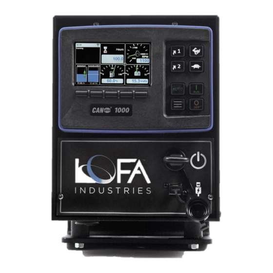
Summary of Contents for Lofa CP1000
- Page 1 CP1000 Installation Manual Part number 463-1000-48 Rev A P a g e...
-
Page 2: Table Of Contents
CP1000 Installation Manual Contents Introduction ..............................3 Mechanical Mounting ........................... 3 AluFlex™ Panels ............................4 Mounting Templates ..........................4 Connector Pinouts ............................7 D21 to Engine pinout ..........................7 D31 IO pinout ............................8 Typical Wiring..............................8 Power and Ground ............................ 8 ECU Power Out ............................ -
Page 3: Introduction
LOFA sales and technical support are available to discuss specialized requirements or custom applications. Mechanical Mounting The CP1000 control panel is adaptable to a wide variety of applications. The included engine harness connector facilitates quick installation. The following is list of installation guidelines: 1. Panel mount shall be a. -
Page 4: Aluflex™ Panels
Isolator mounts should not be twisted when installed. Doing so will lead to premature failure. Mounting Templates The following two (2) pages have the one-to-one hole template for the CP1000 mounting bracket. Part number 463-1000-48 Rev A... - Page 5 CP1000 Installation Manual Part number 463-1000-48 Rev A P a g e...
- Page 6 CP1000 Installation Manual Part number 463-1000-48 Rev A P a g e...
-
Page 7: Connector Pinouts
CP1000 Installation Manual Connector Pinouts There are two connectors on the CP1000. D21 to Engine pinout This connector contains the typical connections required for electrically or mechanically governed engines. The following is the pinout: Comment Comment Signal Signal 1A @... -
Page 8: D31 Io Pinout
CP1000 Installation Manual D31 IO pinout This connector contains the CP1000’s expanded IO. The following is the pinout: Signal Comment Signal Comment 1A @ Switched In 1 Active Low Switched Out 5 System Voltage 1A @ Switched In 2 Active Low... -
Page 9: Starter Power Out
Typically, the engine ECU provides the termination resistor on its end (see engine documentation to verify). The CP1000 has a termination resistor that can be turned off and on as needed. The CP1000’s default configuration has this termination resistor turned on.


Need help?
Do you have a question about the CP1000 and is the answer not in the manual?
Questions and answers