Advertisement
Quick Links
CAN
plus
®
463-0620-01 Rev A. June-2015
© 2006-2015 LOFA Industries, LLC. All rights reserved.
The CANplus logo is a registered trademark of LOFA Industries, Inc. All rights reserved.
LOFA, the LOFA logo, CANplus, CANplus Messenger, CP600, CP620, and CP750 are trademarks of LOFA Industries, Inc. All
rights reserved. Windows is a registered trademark of Microsoft Corporation.
Advertisement

Related Manuals for Lofa CANplus 620


Summary of Contents for Lofa CANplus 620
- Page 1 The CANplus logo is a registered trademark of LOFA Industries, Inc. All rights reserved. LOFA, the LOFA logo, CANplus, CANplus Messenger, CP600, CP620, and CP750 are trademarks of LOFA Industries, Inc. All rights reserved. Windows is a registered trademark of Microsoft Corporation.
- Page 2 620 Operation and Troubleshooting Guide plus ® This page intentionally left blank. 463-0620-01 Rev A. June-2015...
-
Page 3: Safety Symbols
LOFA Industries, LLC has provided this document as a reference. We try to keep this document updated with the latest information regarding your LOFA product. However, changes do occur and LOFA reserves the right to make changes to the design of the LOFA products and supporting documentation without notice. - Page 4 620 Operation and Troubleshooting Guide plus ® AUTO- Start DISCLAIMER This panel/machine may be equipped with an automatic engine start- up system that could result in the automatic starting and stopping of the engine/ machine at any time. As such: •...
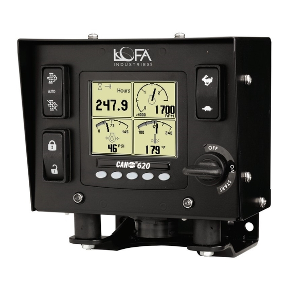
- Page 5 ® General Introduction/ Component Identification/ Overview The LOFA™ CANplus™ 620 control panel is an economical platform for EPA Tier 3, EPA Tier 4 (interim), and EPA Tier 4 electronically governed diesel engines. Graphical gauge pages or a single large analog gauge are displayed on the 4.25” diagonal LCD. Virtually any SAE J1939 parameter reported by the ECU (Engine Control Unit) can be displayed including, but not limited to: RPM, coolant temperature, oil pressure, engine hours, voltage, exhaust emissions system state, and diagnostic codes.
- Page 6 620 Operation and Troubleshooting Guide plus ® NOTE: The CP620 may include other features not shown, such as additional LEDs and different components arrangements to meet engine and/or application requirements. Many operating CP620 parameters can be customized using the Configuration Menu on the display. Gauge layouts, units of measure, display language, and various other parameters such as the full-scale reading of gauges are all adjustable directly with the display.
- Page 7 Restore Defaults in the Configuration Menu to clear the fault. Contact LOFA Industries for assistance if the problem persists. After the splash screen disappears, the display shows readings on its virtual gauges. Initially the analog gauges are displayed but the display uses the screen last displayed on subsequent startups (see Last Screen Store for details).
- Page 8 620 Operation and Troubleshooting Guide plus ® Note: Idle RPM, Intermediate RPM and Run RPM are adjustable in the configuration menu. Minimum Requested RPM and Maximum Requested RPM are generally only configurable using the CANplus Configuration Kit. See Configuration below for more information. CANplus Display Soft buttons simplify the operator interface by displaying a button bar above the buttons when any of the first 4 buttons (buttons 1 to 4 counting from the left) are pressed.
- Page 9 620 Operation and Troubleshooting Guide plus ® button 5 changes to . Pressing button 5 opens a new button bar identifying the gauge adjustment functions. Top left Top right Bottom Bottom Exit menu gauge gauge left gauge right gauge Successive button presses selects a different gauge for the corresponding gauge. Pressing the exit button closes the Quad Adjust menu and saves the page configuration.
- Page 10 620 Operation and Troubleshooting Guide plus ® An active fault indicator is displayed near the upper right corner of the display after the fault list is closed as long as a fault is active. The fault indicator is automatically removed and the fault list is cleared a few seconds after active fault messages stop.
- Page 11 Operation/usage of the CANPlus Configuration Kit is covered in a separate document Please contact LOFA, your machine manufacturer, or your local Distributor for more information regarding the CANPlus Configuration Kit.
-
Page 12: Configuration Menu
620 Operation and Troubleshooting Guide plus ® Configuration Menu Configuration Menu Select configuration submenus The Configuration Menu has four submenus of different parameters and diagnostic information. Display Menu System Menu Throttling Menu Db Viewer Menu Navigation The soft buttons use common functions for navigating all menus. The current selection is indicated by bold font and the arrow icon. - Page 13 620 Operation and Troubleshooting Guide plus ® Display Menu Configure information display Units Menu Set display units Speed MPH (miles per hour, US default) km/h (kilometers per hour, metric default) Kts (knots) Distance Miles (US default) km (kilometers, metric default) NM (nautical miles) Pressure PSI (pounds per square inch, US default)
- Page 14 620 Operation and Troubleshooting Guide plus ® Language Menu Set display language The currently selected language is indicated by the checkmark icon. Language English (default) Svenska (Swedish) Français, (French Canadian) Deutsch (German) Español (Americas Spanish) Italiano (Italian) Nederlands (Dutch) Português (Brazilian Portuguese) Indonesia (Indonesian) russkij jazyk (Russian) Turkish...
- Page 15 620 Operation and Troubleshooting Guide plus ® Max Speed Set analog speedometer full scale speed 15, 20, 25, 30, 35, 40 (default), 45, 50, 55, 60, 70, 75, 80, 85, 95 or 100 km/h 20, 30, 40, 50, 60 (default), 70, 80, 90, 100, 110, 120, 130, 140, 150 or 160 10, 20, 25, 30, 35 (default), 40, 45, 50, 55, 60, 65, 70, 75, 80 or 85 Note: This only sets the range of the analog gauge.
- Page 16 620 Operation and Troubleshooting Guide plus ® System Menu Demo Configure system function Select demo mode Demo Mode generates simulated gauge data to demonstrate display operation. Mode 3 also generates fault messages. Mode 0 – disabled (default) 1 – simulate engine and speed 2 –...
- Page 17 620 Operation and Troubleshooting Guide plus ® Com Viewer Engine Config Display raw J1939 data and engine configuration J1939 Viewer Display engine configuration from ECU J1939 Settings Scrolling display of raw J1939 data Button 1 freezes the scrolling display Set J1939 options Column Value (hexadecimal) Engine Source...
- Page 18 620 Operation and Troubleshooting Guide plus ® Glb (global, default) – display all faults PIN Settings Src (source) – display engine and transmission faults SPN Version Set SPN (Suspect Parameter Number) conversion version Version 1 (default), 2 or 3 New J1939 devices use version 4 to send diagnostic messages.
- Page 19 PIN incorrect (old PIN wrong or new PIN mismatch) not close until the checksum Note: A lost PIN can only be cleared using calculation is complete. the CANplus Configuration Kit or returning the display to LOFA. Throttling Menu Configure throttle control 463-0620-01 Rev A. June-2015...
- Page 20 620 Operation and Troubleshooting Guide plus ® Idle RPM Set idle speed requested Idle RPM (800 RPM default, 10 RPM increment) is the initial speed for Ramp Throttle and Digital Rotary Encoder as well as the low speed for the Two State and Three State Throttle. Idle can be set to compensate for parasitic loads such as hydraulic pumps or compressors.
- Page 21 Further, failure to exactly follow the engine manufacturer instructions and schedules could result in damage to your engine and/or equipment. The LOFA CANplus® display reports emissions messages received from the engine ECU. Depending on the received message, icons or symbols may be displayed on the screen.
- Page 22 620 Operation and Troubleshooting Guide plus ® Examples (not exhaustive) of potential Exhaust Emission system display indications and general definitions are as follow: The engine particulate filter Regeneration of the emissions is potentially in need of system is inhibited due to regeneration.
- Page 23 620 Operation and Troubleshooting Guide plus ® General J1939 Wiring Topology Most electronically governed engine installations include a harness with built in J1939 backbone. Use twisted shielded pair with a drain wire for CANbus wiring terminated with 120Ω resistors at each end. The maximum length for the bus is 40 m (131 feet) and stubs should not exceed 1 meter (39 inches) in length.
- Page 24 Connection to Battery (12V or 24V) LOFA CP620 Panels must be powered via direct battery connection. Powering the CP620 from the engine starter post or other taps into the electrical systems may result in grounding and/or power quality issues which may damage the panel components.
- Page 25 Minimum Starter Relay (Continuous) Rating 5A@12V 3A@24V LOFA provides suitable heavy duty relays and generic starter relay wiring kits in both 12v and 24V; please contact your LOFA reseller for more information. Mounting-Panel The LOFA CP620 Panel design allows much design flexibility with respect to mounting position. However, generally...
- Page 26 Replacement Parts When replacement parts are required, LOFA Industries recommends using replacement parts supplied by LOFA or parts with equivalent specifications. Failure to heed this warning could lead to premature failure, product damage, personal injury or death. 463-0620-01 Rev A. June-2015...
- Page 27 620 Operation and Troubleshooting Guide plus ® General Troubleshooting For additional information, refer to engine manufacturer troubleshooting guide. Display does not display data Possible Cause Possible Remedy Display lost power Turn on key, verify display plugged into harness Engine Source address incorrect Change Engine Address in Configuration Display Address incorrect Change Display Address to 40 (default)
-
Page 28: Software License Agreement
Acceptance of Terms of this Agreement In order to use the LOFA software referenced herein, you must first agree to the provisions of this Agreement. Use of LOFA software is prohibited without acceptance of all the terms in the Agreement. - Page 29 LOFA does not represent or warrant that the Materials will meet any or all of Licensee’s particular requirements, that the operation of the Materials will be error-free or uninterrupted, or that all programming...
- Page 30 Licensee employees, consultants, contractors or agents are agents, employees or joint-venturers of LOFA, nor do they have any authority to bind LOFA by contract or otherwise to any obligation. Licensee agrees not to make any statements that state or imply that LOFA certifies or guarantees Licensee Devices or that Licensee Devices are warranted, tested or approved by LOFA.
- Page 31 620 Operation and Troubleshooting Guide plus ® This page intentionally left blank. 463-0620-01 Rev A. June-2015...
- Page 32 250 Hembree Park Drive, STE 122 Roswell, GA 30076 T: 770.569.9828 F: 770.569.9829 www.LOFA.net 463-0620-01 Rev A. June-2015...
Need help?
Do you have a question about the CANplus 620 and is the answer not in the manual?
Questions and answers