
Related Manuals for Lofa CANplus 640c


Summary of Contents for Lofa CANplus 640c
- Page 1 ® CANplus 640c Control Panel Operation Manual October 2018 LOFA Document No. 463-3002-22...
- Page 2 Disclaimer: The contents of this document are not to be used for advertising, publication, or promotional purposes. Citation of trade names does not constitute an official endorsement or approval of the use of such commercial products. All product names and trademarks cited are the property of their respective owners. DESTROY THIS DOCUMENT WHEN NO LONGER NEEDED.
-
Page 3: Table Of Contents
Autoramp™ ....................17 Configuration ....................19 Display Menu ....................19 ® ® LOFA CANplus Software Suite and LOFA CANplus Config kit ......19 ® LOFA CANplus Software Suite and a USB drive ..........20 Miscellaneous ....................21 Emissions System Functionality .............. - Page 4 6.3.6 Welding on Equipment with Electronic Controls Control System Troubleshooting..............26 ..............27 6.4.1 Testing a Warning or Shutdown ..................27 6.4.2 Testing CAN Diagnostic Trouble Codes (DTC) ..............27 ..................27 6.5.1 Typical SPNs ....................27 6.5.2 FMI LOFA document No. 463-3002-22 Page iii...
- Page 5 This page has been intentionally left blank.
-
Page 6: Important Safety And Emissions Information
LOFA products are not designed or approved for use as critical components of any safety device or system that is intended to prevent bodily injury, protect life, or prevent property damage. - Page 7 LOFA panel applicability, machine guarding, general safety guidelines, labeling, and warnings. The installer of this LOFA panel and/or LOFA harness is responsible for the correct sizing and integration of a suitable fuse/breaker on the un-switched DC circuit supplying power to the LOFA panel.
-
Page 8: Auxiliary Engine Stop Disclaimer
ECU initiated emissions event. LOFA document No. 463-3002-22 Page 3... -
Page 9: Overview
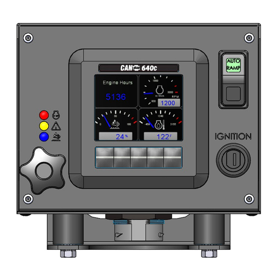
2. Overview 2 Overview The LOFA CP640c control panel is an economical platform for EPA Tier 3, EPA Tier 4 (interim), and EPA Tier 4 electronically governed diesel engines. Graphical gauge pages or a single large analog gauge are displayed on the 3.5-inch diagonal LCD. Virtually any SAE J1939 parameter reported... - Page 10 2. Overview LOFA document No. 463-3002-22 Page 5...
-
Page 11: Display
The display has a number of back-lighting levels allowing the display to be read in the dark. The level is adjusted by pressing buttons 1 (decrease) or button 2 to (increase) illumination. Contrast is adjusted in the same manner using buttons 3 and 4. Page 6 LOFA document No. 463-3002-22 Page 6... -
Page 12: Button Bar
Analog Gauge Pages provide four (4) independently configurable pages of analog gauges. To enable Analog Gauge Pages, press any of the first four (4) buttons to show the top level button bar and then press button 1 to cycle through the pages. LOFA document No. 463-3002-22 Page 7... -
Page 13: Digital Gauge
2 to cycle through the pages. The sixteen (16) gauges are the same for Analog and Digital Gauge Pages. Adjustments in either Analog Gauge Pages or Digital Gauge Pages affect the same gauge in the other mode. Page 8 LOFA document No. 463-3002-22 Page 8... -
Page 14: Single Analog Gauge
An alarm indicator is displayed near the upper right corner of the display as long as alarms are active. The indicator and alarm messages in the list are automatically removed when the alarm has not been received for a few seconds. LOFA document No. 463-3002-22 Page 9... -
Page 15: Service Timers
The menus pages can also be accessed by pressing and holding the optional Rotary Control using LOFA’s RotaryPlus™ technology: • Push and hold the rotary for one (1) second to open menus main page • Move down through the menu choices with clockwise rotations Page 10 LOFA document No. 463-3002-22 Page 10... -
Page 16: Menu Tree
= Admin Display • Language • Units – Distance – Pressure – Volume – Temperature • Button Beep ON/OFF • Gauges – Quad Gauge Pages (configure which gauges will be displayed) – Voltmeter - 12V/24V LOFA document No. 463-3002-22 Page 11... - Page 17 Switch/Rotary – Increments – Max Change Per Second • Autoramp (see section 4.5) – RPM Settings Intermediate – Time Profile Warm Up Ramp to Intermediate Ramp to Run Ramp to Cooldown Cooldown Page 12 LOFA document No. 463-3002-22 Page 12...
-
Page 18: Access Levels
The available menu items are dependent upon the current access level. The current access level is shown in the upper right corner while in the menus. The CP640c supports up to three (3) independent PINs that are configurable. The standard LOFA configuration has the following PINs settings: •... - Page 19 Once an access level is granted, that level is retained until the key is turned off. When the key is turn back to the ON position, the access level reverts back to User and follows the Menu PIN Required setting. Page 14 LOFA document No. 463-3002-22 Page 14...
-
Page 20: Manual Operation
900 RPM. In this case, the engine will not run at 800 RPM despite the CP640c control panel requesting a lower engine speed. The ECU will ignore all RPM requests that are below 900 RPM, resulting in a minimum speed of 900 RPM. LOFA document No. 463-3002-22 Page 15... -
Page 21: Ramp Throttle
4.4 Stopping the Engine To stop the engine simply turn the key to the ”OFF”’ position. Do not use the Auxiliary Engine Stop (if fitted) to stop the engine under normal conditions. Page 16 LOFA document No. 463-3002-22 Page 16... -
Page 22: Autoramp
Run RPM Selects the RPM the control system will request for run speed. The run speed is the normal operating speed. LOFA document No. 463-3002-22 Page 17... - Page 23 RPM and time profiles. When the Cooldown period is over, the panel will automatically shut down the engine and the LED will turn off. Page 18 LOFA document No. 463-3002-22 Page 18...
-
Page 24: Configuration
CANplus Software Suite, which is LOFA’s proprietary configuration software. The software suite is meticulously maintained and regularly updated. These free updates include software enhancements and new functionality, and they ensure compatibility with evolving technologies. The latest update can be found at http://www.lofa.net/updates/. -
Page 25: Lofa Canplus ® Software Suite And A Usb Drive
The CP640c introduces the ability to import and export configurations using a USB drive avoiding ® the need to purchase and have onsite a LOFA CANplus Config kit as well as disconnecting the panel from the engine. The panels USB port can be accessed by simply removing the four (4) front faceplate screws. -
Page 26: Miscellaneous
Use twisted shielded pair with a drain wire for CAN wiring terminated with 120 resistors at each end. The maximum length for the CAN bus is 131 feet (40 m) and stubs should not exceed 39 inches (1m) in length. 6.2.1 Typical J1939 Wiring Topology LOFA document No. 463-3002-22 Page 21... -
Page 27: Engine Harness Connector
LOFA does not recommend using dielectric grease or sealant with sealed connectors. These chemicals may cause seal damage and allow water entry. Use LOFA provided cavity plugs to seal the connector if wires are removed. 6.2.4 Unsealed Connectors For unsealed connectors exposed to the elements, LOFA recommends using dielectric grease to protect contacts. - Page 28 Connected to ‘S’ via 390 resistor Throttle Switch Return Oil Pressure Switch Ground Input CAN Low In/Out J1939 CAN High In/Out J1939 Auxiliary Switch 1 Ground Input Fuel Sender Resistive Table 1. Engine Harness Connection LOFA document No. 463-3002-22 Page 23...
-
Page 29: Harness Routing
Maximum Starter Relay Excitation Current Draw 5A@12V 3A@24V LOFA provides suitable heavy duty relays and generic starter relay wiring kits in both 12v and 24V; please contact your LOFA reseller for more information. 6.3.2 Battery Circuit Requirements Improper wiring can cause electrical noise, unreliable operation and may damage the control system or other components. -
Page 30: Voltage Drop
6. Miscellaneous Disconnecting the battery while the engine is running may result in damage to electrical components. When using a battery disconnect switch, LOFA recommends using a 2 pole switch to disconnect both the battery and alternator output. A maximum of three ring terminals should be connected to a power stud in order to ensure integrity of the connection. -
Page 31: Control System Troubleshooting
Change Display Address to 40 (default) Display configuration problem Reset display using Restore Defaults CAN failure Check CAN (see Testing CAN) ECU not sending data Repair or replace ECU Display shows Bad Device Page 26 LOFA document No. 463-3002-22 Page 26... -
Page 32: Testing A Warning Or Shutdown
SPNs. 6.5.2 FMI FMI codes are defined by SAE J1939-71. Refer to ECU documentation for correct interpretation of FMI codes for a specific SPN. Table 3 on page 29 describes each FMI. LOFA document No. 463-3002-22 Page 27... - Page 33 6. Miscellaneous SPN Description Throttle Position Accelerator Pedal Position Fuel Delivery Pressure Engine Oil Level Engine Oil Pressure Engine Coolant Temperature Coolant Level Table 2. Example SPN Page 28 LOFA document No. 463-3002-22 Page 28...
- Page 34 Data valid but below normal operational range (least severe) Data valid but below normal operational range (moderately severe) Received network data in error thru Reserved for future assignment Not available or condition exists Table 3. FMI Descriptions LOFA document No. 463-3002-22 Page 29...
Need help?
Do you have a question about the CANplus 640c and is the answer not in the manual?
Questions and answers