Advertisement
User Manual
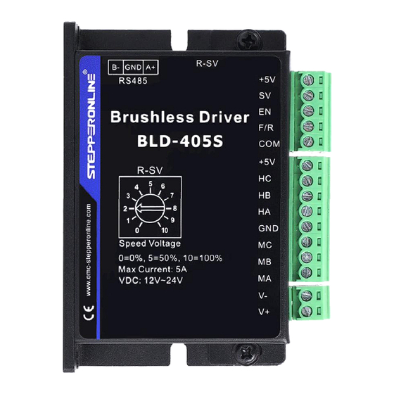
BLD-405S
Brushless DC Motor Driver
©2023 All Rights Reserved
Address: 15-4, #799 Hushan Road, Jiangning, Nanjing, China
Tel: 0086-2587156578
Web: www.omc-stepperonline.com
Sales: sales@stepperonline.com
Support: technical@stepperonline.com
Read the operating instructions carefully before putting the driver into operation with power
Advertisement
Table of Contents

Related Manuals for StepperOnline BLD-405S


Summary of Contents for StepperOnline BLD-405S
- Page 1 User Manual BLD-405S Brushless DC Motor Driver ©2023 All Rights Reserved Address: 15-4, #799 Hushan Road, Jiangning, Nanjing, China Tel: 0086-2587156578 Web: www.omc-stepperonline.com Sales: sales@stepperonline.com Support: technical@stepperonline.com Read the operating instructions carefully before putting the driver into operation with power...
-
Page 2: Specifications
BLD-405S BLDC Brushless Driver Introduction This series of control drivers uses a closed-loop speed controller and employs IGBT and MOS power devices. It utilizes the Hall signals of the DC brushless motor after frequency multiplication to achieve closed-loop speed control. The control loop has a PID speed regulator, making the system control stable and reliable. - Page 3 BLD-405S BLDC Brushless Driver 2.3 Mechanical Specification (Unit: mm [1inch=25.4mm]) Dimension: 86x55x21mm 2.4 Safety Precautions Do not measure or touch any components without housing while operating This product is powered by a DC power supply. Please confirm that the positive and negative poles of the power supply are correct before powering on.
-
Page 4: Terminal Connection
BLD-405S BLDC Brushless Driver 3. Terminal Connection 3.1 Power Input Terminal Name Description 12VDC~36VDC input GND input 3.2 Motor Input Terminal Name Description Motor phase A Motor phase B Motor phase C Negative ground wire of Hall signal Hall signal A phase input terminal... -
Page 5: Functions And Usage
BLD-405S BLDC Brushless Driver Wiring diagram of the driver and the brushless motor: 4. Functions and Usage 4.1 Speed Adjustment Method 4.1.1 External input speed regulation: Connect the two fixed terminals of an external potentiometer to the GND and +5v terminals of the driver respectively, and connect the adjustment terminal to the SV terminal, and then you can use the external potentiometer (10K~50K) to adjust the speed. -
Page 6: Communication Method
Sensorless control mode STEPPERONLINE drivers can be used for sensorless brushless motors. But it should be noted that since our brushless driver is mainly used for our brushless motor with sensors, its built-in program is also used for motors with sensors. - Page 7 BLD-405S BLDC Brushless Driver Address Parameter name Setting range Default unit Remark $8000 First byte: control bit state First byte: Second byte: Hall angle and Bit0: EN number of pole pairs of motors Bit1: FR Bit2: BK Bit3: NW Bit4: MDX...
- Page 8 BLD-405S BLDC Brushless Driver $801B First byte: the fault status Bit0: locked rotor Bit1: over current The second byte: Motor running Bit2: hall value state abnormal Bit3: Bus voltage too low Bit4: Bus voltage too high Bit5: Current peak alarm...
Need help?
Do you have a question about the BLD-405S and is the answer not in the manual?
Questions and answers