Table of Contents
Advertisement
Available languages
Available languages
Quick Links
π
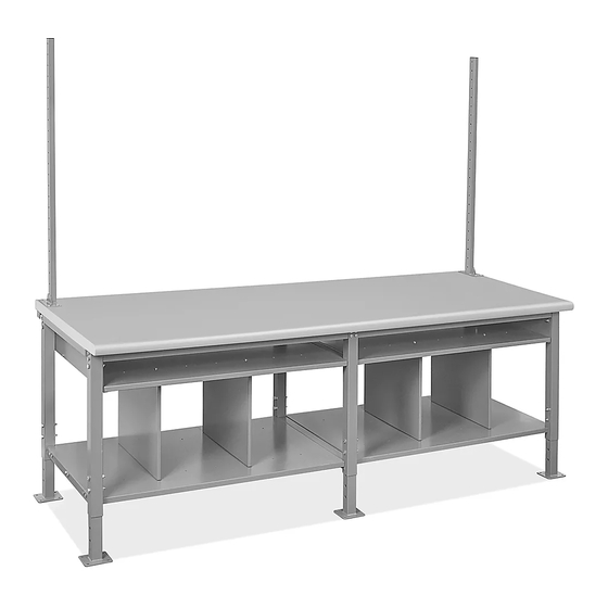
H-8226
96" PACKING STATION
TOOLS NEEDED
Electric
1/4" Drill Bit
Drill
Phillips Head
Phillips
Drill Bit
Screwdriver
10
2
6
3
CAUTION! Some parts may have sharp edges.
Care must be taken when handling various
pieces to avoid injury. For your safety, wear a
pair of work gloves when assembling.
NOTE: Hardware packs are included in shelf
and frame packaging. Pack may include more
hardware than needed.
PAGE 1 OF 33
1-800-295-5510
uline.com
Allen Wrench
(included)
Three Person Assembly
10
11
6
8
5
1
7
9
8 mm Wrench
10 mm Wrench
13 mm Wrench
17 mm Wrench
Required
PARTS
PARTS
#
DESCRIPTION
1
Center Leg
2
Outside Leg
3
Adjustable Foot
4
Frame Support Bar
5
4" High Storage Shelf – 2-Piece
6
Storage Shelf Support Bracket
7
Full Depth Bottom Shelf – 2-Piece
8
Center Leg Support Bar
9
Bottom Shelf Divider
10
Upright
11
Tabletop
4
M8 x 35 Hex Bolt x 12
M6 x 15 Hex Bolt x 4
M6 Phillips Head Bolt x 16
M6 Flange Nut x 28
M8 Nut x 18
Para Español, vea páginas 12-22.
Pour le français, consulter les pages 23-33.
QTY.
Hardware Kit
M8 x 65 Hex Bolt x 22
M10 x 65 Hex Bolt x 16
M6 x 70 Hex Bolt x 8
6 x 30 mm Wood Screw x 30
M10 Nut x 16
Flat Washer x 8
1
2
6
4
1
2
1
1
4
2
1
0324 IH-8226
Advertisement
Table of Contents

Related Manuals for U-Line H-8226


Summary of Contents for U-Line H-8226
- Page 1 Para Español, vea páginas 12-22. Pour le français, consulter les pages 23-33. π H-8226 1-800-295-5510 uline.com 96" PACKING STATION TOOLS NEEDED Electric 1/4" Drill Bit Allen Wrench 8 mm Wrench Drill (included) 10 mm Wrench 13 mm Wrench 17 mm Wrench...
- Page 2 ASSEMBLY LEGS AND FRAME ASSEMBLY 3. Place center leg support bar (8) between frame support bars (4) on top of the center leg. Fasten NOTE: Tabletops add 1⁄ – 1⁄" depending on center leg support bar to frame support bars and top purchased.
-
Page 3: Top Assembly
ASSEMBLY CONTINUED 2. Fasten end of each shelf piece to the leg brace of NOTE: Additional pre-drilled holes in tabletop the outside legs with six M8 x 35 hex bolts and six are used for a different product and will not M8 nuts per shelf using a 13 mm wrench. -
Page 4: Upright Assembly
ASSEMBLY CONTINUED BOTTOM SHELF DIVIDER ASSEMBLY Figure 11 Four bottom shelf dividers are included with packing station. To attach, slide shelf dividers between full depth bottom shelf and 4" high storage shelf and align with two pre-drilled holes in each shelf. Fasten each divider with four M6 Phillips head bolts and four M6 flange nuts using a Phillips screwdriver and 10 mm wrench. -
Page 5: Optional Accessories
OPTIONAL ACCESSORIES NOTE: The following products are optional accessories. Mounting hardware is included with each accessory. DESCRIPTION QTY. Bin Rail Monitor Arm** Reel Holder Bracket Reel Holder 12" Deep Top Shelf Bracket 18, 19 12" Deep Top Shelf 12" Deep Top Shelf Divider 16"... -
Page 6: Cable Management
OPTIONAL ACCESSORIES CONTINUED MONITOR ARM ASSEMBLY Easy-adjust monitor mount includes a built-in counterweight system for free-range motion. Arm in Line up monitor arm mounting bracket (2) with mount may need to be adjusted to allow monitor to stop uprights at desired height. at desired position. - Page 7 OPTIONAL ACCESSORIES CONTINUED 12" DEEP TOP SHELF ASSEMBLY 16" DEEP BOX SHELF ASSEMBLY Line up shelf brackets (5) with uprights at desired height. Line up shelf brackets (8) with uprights at desired height. 2. Secure to uprights with four 1⁄" bolts and flange 2.
-
Page 8: Light Kit Assembly
OPTIONAL ACCESSORIES CONTINUED LIGHT KIT ASSEMBLY 5. Attach hanging chains to LED shop light (11) and mount to "S" hooks. (See Figure 31) Line up light brackets (12) with uprights at desired height. 2. Secure to uprights with four 2" bolts and flange nuts. Figure 31 (See Figure 28) Figure 28... -
Page 9: Fan Assembly
OPTIONAL ACCESSORIES CONTINUED TAPE GUN HOLDER ASSEMBLY FAN ASSEMBLY NOTE: Tape Gun Holder can be attached to NOTE: Fan comes with 6" and 10" long bracket. uprights or bin rail. Choose desired bracket based on application. If attaching to bin rail, no assembly is needed. Slot 6"... -
Page 10: Caster Assembly
OPTIONAL ACCESSORIES CONTINUED HORIZONTAL PAPER CUTTER ASSEMBLY Figure 40 Box shelf can support the attachment of Uline 24" or 36" Horizontal Paper Cutters (H-194, H-195, H-1244 and H-1245). To attach, position the paper cutter underneath the shelf and align with two front and two rear pre-drilled holes in shelf. -
Page 11: Troubleshooting
TROUBLESHOOTING OPERATING ISSUE RECOMMENDATIONS Accessory too short/doesn't fit between Ensure uprights are facing the right direction. uprights. (See Upright Assembly in instructions) M8 hex bolts have varying size heads. 13 mm or 14 mm open end wrench(s) may be needed. Tabletop is hard to drill through due to Remove the storage shelf support brackets and re-attach after clearance in step 2 of Top Assembly. -
Page 12: Herramientas Necesarias
π H-8226 800-295-5510 uline.mx ESTACIÓN DE EMPAQUE DE 96" HERRAMIENTAS NECESARIAS Llave de 8 mm Taladro Broca de 1/4" Llave Allen Eléctrico (incluida) Llave de 10 mm Llave de 13 mm Llave de 17 mm Broca Desarmador Se Requiere Armar... - Page 13 ENSAMBLE ENSAMBLE DE LAS PATAS Y ARMAZÓN 3. Coloque la barra de soporte de la pata central (8) entre las barras de soporte del armazón (4) encima NOTA: Las cubiertas de mesa agregan 1⁄ – 1⁄" de la pata central. Una la barra de soporte de dependiendo de la cubierta adquirida.
- Page 14 CONTINUACIÓN DEL ENSAMBLE 2. Una el extremo de cada pieza de la repisa al soporte Diagrama 8 de las patas exteriores con seis pernos M8 x 35 y seis tuercas M8 por repisa utilizando una llave de 13 mm. Tornillo para (Vea Diagrama 6) Madera Pernos...
- Page 15 CONTINUACIÓN DEL ENSAMBLE ENSAMBLE DE DIVISORES PARA REPISA NOTA: La repisa de almacenamiento de 4" de alto es un diseño de dos piezas. Un extremo de INFERIOR cada pieza descansa sobre el soporte para repisa de almacenamiento. El otro extremo se La estación de empaque incluye cuatro divisores para atornilla al soporte intermedio de la pata central.
-
Page 16: Accesorios Opcionales
ACCESORIOS OPCIONALES NOTA: Los siguientes productos son accesorios opcionales. La tornillería de instalación se incluye con cada accesorio. DESCRIPCIÓN CANT. Riel para Gaveta Brazo para Monitor** Brazo del Soporte del Carrete Soporte del Carrete Soporte para Repisa Superior de 12" de Profundidad 18, 19 Repisa Superior de 12"... - Page 17 CONTINUACIÓN DE ACCESORIOS OPCIONALES ENSAMBLE DEL BRAZO PARA MONITOR Diagrama 19 1. Alinee el brazo de soporte de instalación para monitor (2) con los postes a la altura deseada. 2. Fíjelo a los postes con dos pernos de cabeza Allen M6 x 35 mm o M6 x 50 mm, dos rondanas planas Llave Rondana...
- Page 18 CONTINUACIÓN DE ACCESORIOS OPCIONALES ENSAMBLE DE REPISA SUPERIOR DE 12" ENSAMBLE DE REPISA PARA CAJAS DE 16" DE PROFUNDIDAD DE PROFUNDIDAD Alinee los soportes para repisa (5) con los postes a la Alinee los soportes para repisa (8) con los postes a la altura deseada.
- Page 19 CONTINUACIÓN DE ACCESORIOS OPCIONALES KIT DEL ENSAMBLE DEL SOPORTE LIGERO 5. Fije las cadenas colgantes a la luz LED para taller (11) e instálelas en los ganchos en "S". (Vea Diagrama 31) 1. Alinee los soportes ligeros (12) con los postes a la altura deseada.
- Page 20 CONTINUACIÓN DE ACCESORIOS OPCIONALES ENSAMBLE DEL SOPORTE PARA ENSAMBLE DEL VENTILADOR DESPACHADOR DE CINTA NOTA: El ventilador viene con soportes de 6" y 10" de largo. Elija el soporte que desee basado en NOTA: El Soporte para Despachador de Cinta la aplicación.
- Page 21 CONTINUACIÓN DE ACCESORIOS OPCIONALES ENSAMBLE DE LA CORTADORA DE PAPEL Diagrama 40 HORIZONTAL La repisa para cajas es compatible con Cortadoras de Papel Horizontales Uline de 24" o 36" (H-194, H-195, H-1244 y H-1245). Para fijarla, coloque la cortadora de papel debajo de la repisa y alinee con los dos orificios frontales y posteriores preperforados.
-
Page 22: Solución De Problemas
SOLUCIÓN DE PROBLEMAS PROBLEMA DE FUNCIONAMIENTO RECOMENDACIONES Accesorio demasiado corto / no cabe Asegúrese de que los postes apunten a la dirección correcta. entre los postes. (Vea Ensamble de Postes en Instrucciones) Los pernos hexagonales M8 varían en Podría necesitar llave(s) de boca abierta de 13 mm o 14 mm. tamaños de cabeza. -
Page 23: Outils Requis
π H-8226 1-800-295-5510 uline.ca POSTE D'EMBALLAGE – 96 PO OUTILS REQUIS Clé de 8 mm Perceuse Mèche de 1/4 po Clé Allen électrique (inclus) Clé de 10 mm Clé de 13 mm Clé de 17 mm Mèche de perceuse Tournevis Montage à... -
Page 24: Montage
MONTAGE MONTAGE DES PIEDS ET DU CADRE 3. Placez la barre de support pour pied central (8) entre les barres de support de cadre (4) sur le dessus du pied central. Fixez la barre de support du REMARQUE : Les surfaces de table ajoutent de pied central aux barres de support de cadre et au 1 ½... - Page 25 MONTAGE SUITE 2. Fixez chaque extrémité des pièces de la tablette à Vis à bois Figure 8 l'entretoise des pieds extérieurs à l'aide de six boulons Vis à bois hexagonaux M8 x 35 et six écrous M8 par tablette en vous servant d'une clé...
- Page 26 MONTAGE SUITE MONTAGE DES SÉPARATEURS DE TABLETTE REMARQUE : La tablette de rangement de 4 po de haut comporte deux pièces. Une extrémité INFÉRIEURE de chaque pièce repose sur la ferrure de support de la tablette de rangement. L'autre 1. Quatre séparateurs de tablette inférieure sont inclus extrémité...
-
Page 27: Accessoires Optionnels
ACCESSOIRES OPTIONNELS REMARQUE : Les articles suivants sont des accessoires optionnels. Le matériel d'installation est compris avec chaque accessoire. DESCRIPTION QTÉ Rail pour bacs Bras de moniteur** Support de porte-rouleau Porte-rouleau Console de tablette supérieure de 12 po de profondeur 18, 19 Tablette supérieure de 12 po de profondeur Séparateur de tablette supérieure de 12 po de profondeur... -
Page 28: Gestion Des Câbles
ACCESSOIRES OPTIONNELS SUITE MONTAGE DU BRAS DE MONITEUR Le support de moniteur d'ajustement facile comprend un système de contrepoids intégré pour un large champ de 1. Alignez le support de fixation du bras de moniteur (2) mobilité. Il se peut qu'il soit nécessaire d'ajuster le bras sur les montants à... - Page 29 ACCESSOIRES OPTIONNELS MONTAGE DE LA TABLETTE SUPÉRIEURE DE MONTAGE DE LA TABLETTE SUPÉRIEURE À BOÎTE DE 16 PO DE PROFONDEUR 12 PO DE PROFONDEUR Alignez les consoles de tablette (8) sur les montants à la Alignez les consoles de tablette (5) sur les montants à hauteur voulue.
- Page 30 ACCESSOIRES OPTIONNELS MONTAGE DE L'ÉCLAIRAGE 5. Accrochez les chaînes de suspension à l'éclairage d'atelier à DEL (11), puis fixez-les sur les crochets en 1. Alignez les supports d'éclairage (12) sur les montants " S ". (Voir Figure 31) à la hauteur voulue. 2.
- Page 31 ACCESSOIRES OPTIONNELS SUITE MONTAGE DU PORTE-DÉVIDOIR DE MONTAGE DU VENTILATEUR RUBAN ADHÉSIF REMARQUE : Le ventilateur est livré avec un support de fixation d'une longueur de 6 po REMARQUE : Le porte-dévidoir de ruban adhésif et un autre de 10 po. Choisissez le support peut être fixé...
- Page 32 ACCESSOIRES OPTIONNELS SUITE MONTAGE DU COUPE-PAPIER Figure 40 HORIZONTAL La tablette pour boîtes a été conçue pour permettre la fixation de coupe-papiers horizontaux Uline de 24 po ou 36 po (H-194, H-195, H-1244 et H-1245). Placez le coupe-papier sous la tablette et alignez-le sur deux trous prépercés à...
-
Page 33: Dépannage
DÉPANNAGE PROBLÈME RECOMMANDATIONS Accessoire trop court ne tenant pas entre les Assurez-vous que les montants sont orientés dans la bonne montants. direction. (Voir la section Montage du montant dans les directives) Les boulons hexagonaux M8 ont des têtes Une ou plusieurs clés à fourche de 13 mm ou 14 mm peuvent de tailles différentes.
Need help?
Do you have a question about the H-8226 and is the answer not in the manual?
Questions and answers