
Related Manuals for FS S3100 Series


Summary of Contents for FS S3100 Series
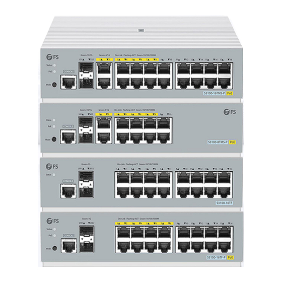
- Page 1 S3100 Series Switch Hardware Installation and Maintenance Guide V1.0.2306A Innovation · Expertise · Agility...
- Page 2 Safety Statement: • To avoid harm to people and equipment, please read the safety recommendations in the Safety Precautions for FS Switches before installing the FS Switch. Verify that the requirements described in the Safety Precautions for FS •...
-
Page 3: Table Of Contents
Contents 1. Hardware Installation and Parts Replacement 1.1 Installation Procedure 1.2 Installation Preparation 1.3 Installing a Switch 1.4 Connecting a Switch 1.5 Post-Installation Checks 1.6 System Commissioning 1.7 Parts Replacement 2. Troubleshooting After Installatio 2.1 Troubleshooting Flowchart 2.2 Guide to Using Switches 2.3 Guide to Using Optical Modules Innovation ·... -
Page 4: Hardware Installation And Parts Replacement
Hardware Installation and Parts Replacement The S3100 series switches are extremely simplified optical switches designed for full optical network scenarios. They employ a completely new hardware architecture to achieve silent and energy-efficient operation, flexible installation, and incorporate an internal power supply, metal casing, and network ports in the design, ensuring stability and reliability. -
Page 5: Installation Procedure
Hardware Installation and Parts Replacem Switch Hardware Installation and Maintenance Guide 1.1 Installation Procedure Installation Preparation Installing a Switch Connecting a Switch System Commissioning Post-Installation Checks 1.2 Installation Preparation Confirm the following before installation: The installation site provides sufficient space for heat dissipation. •... - Page 6 Hardware Installation and Parts Replacem Switch Hardware Installation and Maintenance Guide 1.2.2 Mounting the Cabinet or Rack When mounting the cabinet, please note the following: • All expansion bolts for fastening the cabinet base to the ground should be installed and tightened in sequence from bottom to up (large flat washer, spring washer, and nut), and the installation holes on the base and the expansion bolts are aligned.
-
Page 7: Installing A Switch
Dust-free paper and fiber end-face microscope Meters Multimeter, bit error rate tester (BERT), and optical power meter The S3100 series switch is delivered without a tool kit. You need to prepare a tool kit by yourself. • 1.3 Installing a Switch Precautions: Before installing the switch in a cabinet, please check whether the racks are properly positioned. - Page 8 Hardware Installation and Parts Replacem Switch Hardware Installation and Maintenance Guide Procedure: Remove screws (packaged with the lugs) and attach one end of the bracket to the switch, as as shown below: Figure 1: Cabinet Lug Installation As shown in the diagram below, place the switch horizontally in the cabinet, fixing the other end of the bracket to the front rail of the cabinet using M6 screws and corresponding floating nuts.
- Page 9 Figure 3: Cabinet Lug Installation 1.3.2 Under-table Mounting The S3100 series switch supports direct installation under a table, requiring adequate heat dissipation space. Installation requirements: The area beneath the table must be in a well-ventilated situation. 2. No obstruction within 90mm below the switch.
- Page 10 Hardware Installation and Parts Replacement Switch Hardware Installation and Maintenance Guide Procedure: Extract screws (packaged with the lugs), attach one end of the lugs (rotated 90 degrees) to the switch, as shown below: Figure 4: Under-table Mounting Secure the switch to the wall using expansion screws. The location where the device is mounted and operated must be subject to movement restrictions.
- Page 11 Switch Hardware Installation and Maintenance Guide 1.3.3 Mounting the Switch on the wall/table The S3100 series switch supports direct installation on walls or tables. Installation requirements: 1. No obstruction within 90mm in front of the switch. Specific installation process is as follows:...
- Page 12 1.3.4 Mounting in Weak Current Box The S3100 series switch supports installation within a weak current box. Installation requirements: Ambient temperature around the weak current box should be ≤40 ℃. 2. Size requirement for the weak current box and opening area proportions:...
- Page 13 Hardware Installation and Parts Replacem Switch Hardware Installation and Maintenance Guide Within 20CM of the weak current box's front panel, there should be no obstructions to ensure proper ventilation and prevent poor heat dissipation. 4. Stacking multiple devices within the weak current box is strictly prohibited . - Weak current box shelf installation method 1: 1.
- Page 14 Hardware Installation and Parts Replacement Switch Hardware Installation and Maintenance Guide 2. Place the device on the shelf, connect network cables to the network port. Connect the power cord to the device, confirm power supply, close the weak current box door, and lock it with a key.
- Page 15 Hardware Installation and Parts Replacement Switch Hardware Installation and Maintenance Guide 2. Place the device on the shelf, connect network cables to the network port. 3. Connect the power cord to the device, confirm power supply, close the weak current box door, and lock it with a key.
-
Page 16: Connecting A Switch
1.4.1 Connecting a Grounding Cable The S3100 series mainframe has a protected grounding point on its rear panel. It should be initially connected to the grounding terminal of the rack, and then the cabinet's grounding terminal is connected to the grounding row in the equipment room. - Page 17 Hardware Installation and Parts Replacement Switch Hardware Installation and Maintenance Guide • Power cables must be buried underground or routed indoors and can not be led into the equipment room aerially. • Do not power on a switch before you finish installing the switch and connecting cables. Procedure: Wear an ESD wrist strap or ESD gloves.
- Page 18 Hardware Installation and Parts Replacement Switch Hardware Installation and Maintenance Guide 1.4.5 Connecting High-speed Cables • Before connecting cables, take ESD protection measures, for example, wear ESD gloves or an ESD wrist strap. • Both ends of an idle high-speed cable must be covered by an ESD cap. •...
-
Page 19: Post-Installation Checks
Hardware Installation and Parts Replacement Switch Hardware Installation and Maintenance Guide To remove a high-speed cable, gently push the cable connector and then pull the handle of the connector. Do not directly pull the cable connector with force. See Figure 8. Figure 8: Removing a High-speed Cable 6. -
Page 20: System Commissioning
Hardware Installation and Parts Replacem Switch Hardware Installation and Maintenance Guide • The cabinet and all cables are securely fastened. • The switch has been installed in the cabinet. • Maintain a minimum clearance of 200mm (7.87 in.) around the switch for air circulation. 1.5.2 Verifying Cable Connection The UTP and STP cables match with the interface type. - Page 21 Hardware Installation and Parts Replacem Switch Hardware Installation and Maintenance Guide Step 1: Connecting the Ethernet Cable Plug the DB-9 connector of the Ethernet cable into the serial port of the PC. 2. Connect RJ45 connector of the Ethernet cable to the console port of the switch. Step 2: Check the Serial Port Number Open Device Manager on the computer and check the serial port number.
- Page 22 Hardware Installation and Parts Replacement Switch Hardware Installation and Maintenance Guide Step 4: Setting Terminal Parameters Parameter requirements: Baud rate is 9600, connection type is Serial, fill in COM port number according to the actual situation. The specific diagram is as follows. Figure 10: Setting Terminal Parameters Innovation ·...
-
Page 23: Parts Replacement
Hardware Installation and Parts Replacem Switch Hardware Installation and Maintenance Guide Step 5: Once the serial port parameters are set, click <Open> to enter the CLI interface 1.6.2 Verifying Cable Connection Check before power • Check that the switch is fully grounded. •... - Page 24 Hardware Installation and Parts Replacem Switch Hardware Installation and Maintenance Guide • When replacing an optical module, ensure that no optical fiber is connected to the optical module. Install or remove optical fibers carefully to avoid damages to fiber connectors. Exercise caution when installing or removing optical fibers to prevent damage to the optical module.
- Page 25 Hardware Installation and Parts Replacem Switch Hardware Installation and Maintenance Guide 4. Pull out the optical module, plug the dustproof plug and dispose of it. - There are two types of buckles on the optical module. A pull-rod handle that needs to be turned over to open, as shown in Figure 16.
- Page 26 Hardware Installation and Parts Replacem Switch Hardware Installation and Maintenance Guide 5. Take out the new optical module from the package, and slowly insert it into the interface until you hear a "pop" sound, indicating that it has been installed in place. Find the fiber to be connected, find the interface corresponding to the fiber through the label on the fiber, remove the dust cap and connect the fiber to the interface.
-
Page 27: Troubleshooting After Installation
Troubleshooting After Installation Innovation · Expertise · Agility... -
Page 28: Troubleshooting Flowchart
Check the connector of power supply module each module Check the installation of Check the LEDs on the device other modules Check serial port connection Check the cable connection and parameters Contact FS Technical Support Innovation · Expertise · Agility... -
Page 29: Guide To Using Switches
Fault Symptom The login password is forgotten. Handling Method Contact FS technical support. Fault 2: The AC power module does not work Fault Symptom All LEDs on the front panel are off. The fan status LED is off, and the fan does not rotate. The power supply status LED is off. - Page 30 Sometimes glitches can appear on these hardware. 5. Contact Vendor Support: If there is still no output on the serial port, please contact FS technical support. Fault 5: The serial port console output is garbled Fault Symptom The serial port console output is garbled.
-
Page 31: Guide To Using Optical Modules
Troubleshooting After Installation Switch Hardware Installation and Maintenance Guide Check whether the receive and transmit ends are reversed. The transmit end of an optical port must be connected to the receive end at the other end. You can confirm both ends by exchanging the connection order of two fiber cables. - Page 32 Troubleshooting After Installation Switch Hardware Installation and Maintenance Guide If the latch boss is not secured, the gold finger of the optical module is not in good contact with the connector on the board. In this case, the link may be connected but optical signals will be cut off or the optical module will be loosened when the optical module is shaken or hit.
- Page 33 Troubleshooting After Installation Switch Hardware Installation and Maintenance Guide Place at least three cleaning tissues on the work bench. As shown in Figure 19, wipe the end of an • optical connector from left to right or from right to left on a cleaning tissue, and then move the connector end to the unused part of the cleaning tissue to continue.
- Page 34 Troubleshooting After Installation Switch Hardware Installation and Maintenance Guide Figure 22: Installing a Protective Cap on a Fiber 4. If a receptacle or an optical connector has not been used for a long time and is not covered with a protective cap, you need to clean it before using it.
- Page 35 Troubleshooting After Installation Switch Hardware Installation and Maintenance Guide Before using an optical time-domain reflectometer (OTDR) to test the connectivity or the attenuation of optical signals, disconnect the optical fibers from the optical module. Otherwise, the optical module will be burnt. 2.
- Page 36 FS has invested resources in product R&D, quality control, intelligent manufacturing, industry-leading experts, professional technical support, and networking solutions. All is to provide customers with higher-performance, lower-power consumption, and the most cost-effective products, promoting clients' network upgrades. For more information and technical support, welcome to contact us at www.fs.com/contact_us...
Need help?
Do you have a question about the S3100 Series and is the answer not in the manual?
Questions and answers