Table of Contents
Advertisement
Quick Links
Advertisement
Table of Contents

Related Manuals for Gree GWHDNK6PO


Summary of Contents for Gree GWHDNK6PO
- Page 1 Change for life Service Manual GREE ELECTRIC APPLIANCES, INC. OF ZHUHAI...
-
Page 2: Table Of Contents
Table of Contents Service Manual Part I : Technical Information ............1 1. Summary .......................1 2. Specifications ....................2 3. Outline Dimension Diagram .............12 4. Refrigerant System Diagram ..........14 5. Electrical Part ....................18 5.1 Wiring Diagram .......................18 5.2 PCB Printed Diagram ....................21 6. -
Page 3: Part I : Technical Information
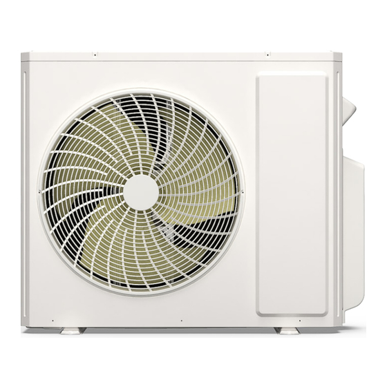
1. Summary Service Manual Outdoor Unit: GWHD(18)NK6PO GWHD(24)NK6PO GWHD(28)NK6PO GWHD(36)NK6PO GWHD(42)NK6PO Model list: Model Product code GWHD(18)NK6PO CB228W18600 CB228W18700 GWHD(24)NK6PO CB228W18701 CB228W18300 GWHD(28)NK6PO CB228W18301 CB228W18900 GWHD(36)NK6PO CB228W18901 CB228W18800 GWHD(42)NK6PO CB228W18801 Technical Information... -
Page 4: Specifications
2. Specifications Service Manual Model GWHD(18)NK6PO Product Code CB228W18600 Rated Voltage 220-240 Rated Frequency Phases Cooling Capacity Heating Capacity 5.65 Cooling Power Input 1.38 Heating Power Input 1.27 Cooling Current Input 6.12 Heating Current Input 5.63 Rated Power Input Rated Current 3.84 4.45 Compressor Manufacturer... - Page 5 2. Specifications Service Manual Cross-sectional Area of Power Cable Conductor Recommended Power Cable Connection Pipe Connection Method Flare Connection Not Additional Gas Connection Pipe Length Connection Pipe Gas Additional Charge Outer Diameter of Liquid Pipe1 inch Outer Diameter of Gas Pipe1 inch Outer Diameter of Liquid Pipe2 inch...
- Page 6 2. Specifications Service Manual Model GWHD(24)NK6PO Product Code CB228W18700 CB228W18701 Rated Voltage 220-240 Rated Frequency Phases Cooling Capacity Heating Capacity Cooling Power Input 1.96 Heating Power Input Cooling Current Input Heating Current Input 8.87 Rated Power Input Cooling: 3.4 / Heating: 3.0 Rated Current Cooling: 15 / Heating: 14.6 3.72...
- Page 7 2. Specifications Service Manual Cross-sectional Area of Power Cable Conductor Recommended Power Cable Connection Pipe Connection Method Flare Connection Not Additional Gas Connection Pipe Length Connection Pipe Gas Additional Charge Outer Diameter of Liquid Pipe1 inch Outer Diameter of Gas Pipe1 inch Outer Diameter of Liquid Pipe2 inch...
- Page 8 2. Specifications Service Manual Model GWHD(28)NK6PO Product Code CB228W18300 CB228W18301 Rated Voltage 220-240 Rated Frequency Phases Cooling Capacity Heating Capacity Cooling Power Input 1.88 Heating Power Input 2.12 Cooling Current Input 8.34 Heating Current Input 9.41 Rated Power Input Rated Current 15.97 4.36 4.15...
- Page 9 2. Specifications Service Manual Cross-sectional Area of Power Cable Conductor Recommended Power Cable Connection Pipe Connection Method Flare Connection Not Additional Gas Connection Pipe Length Connection Pipe Gas Additional Charge Outer Diameter of Liquid Pipe1 inch Outer Diameter of Gas Pipe1 inch Outer Diameter of Liquid Pipe2 inch...
- Page 10 2. Specifications Service Manual Model GWHD(36)NK6PO Product Code CB228W18900 CB228W18901 Rated Voltage 220-240 Rated Frequency Phases Cooling Capacity 10.6 Heating Capacity 11.4 Cooling Power Input 2.65 Heating Power Input 2.85 Cooling Current Input 11.76 Heating Current Input 12.64 Rated Power Input Cooling: 4.6 / Heating: 5.0 Rated Current Cooling: 20.41 / Heating: 21.74...
- Page 11 2. Specifications Service Manual Cross-sectional Area of Power Cable Conductor Recommended Power Cable Connection Pipe Connection Method Flare Connection Not Additional Gas Connection Pipe Length Connection Pipe Gas Additional Charge Outer Diameter of Liquid Pipe1 inch Outer Diameter of Gas Pipe1 inch Outer Diameter of Liquid Pipe2 inch...
- Page 12 2. Specifications Service Manual Model GWHD(42)NK6PO Product Code CB228W18800 CB228W18801 Rated Voltage 220-240 Rated Frequency Phases Cooling Capacity 12.3 Heating Capacity 12.6 Cooling Power Input Heating Power Input Cooling Current Input 13.75 Heating Current Input 14.2 Rated Power Input Cooling: 4.6 / Heating: 5.0 Rated Current Cooling: 20.41 / heating: 21.74 3.97...
- Page 13 2. Specifications Service Manual Cross-sectional Area of Power Cable Conductor Recommended Power Cable Connection Pipe Connection Method Flare Connection Not Additional Gas Connection Pipe Length Connection Pipe Gas Additional Charge Outer Diameter of Liquid Pipe1 inch Outer Diameter of Gas Pipe1 inch Outer Diameter of Liquid Pipe2 inch...
-
Page 14: Outline Dimension Diagram
3. Outline Dimension Diagram Service Manual GWHD(18)NK6PO Unit: mm GWHD(24)NK6PO GWHD(28)NK6PO Unit: mm Technical Information... - Page 15 3. Outline Dimension Diagram Service Manual GWHD(36)NK6PO GWHD(42)NK6PO 1020 Unit: mm Technical Information...
-
Page 16: Refrigerant System Diagram
4. Refrigerant System Diagram Service Manual GWHD(18)NK6PO outdoor indoor filter outdoor heat exchanger 4-way valve A heat exchanger filter discharge silencer B heat exchanger discharge temperature filter sensor gas -liquid separator A1: A-unit electronic expansion valve B1: B-unit electronic expansion valve A2: A-unit gas pipe temperature sensor B2: B-unit gas pipe temperature sensor A3: A-unit liquid pipe temperature sensor... - Page 17 4. Refrigerant System Diagram Service Manual GWHD(24)NK6PO outdoor indoor filter A heat exchanger outdoor heat exchanger filter 4-way valve B heat exchanger filter discharge silencer discharge temperature sensor C heat exchanger gas -liquid separator filter A1: A-unit electronic expansion valve B1: B-unit electronic expansion valve C1: C-unit electronic expansion valve A2: A-unit gas pipe temperature sensor...
- Page 18 4. Refrigerant System Diagram Service Manual GWHD(28)NK6PO GWHD(36)NK6PO outdoor indoor filter A heat exchanger outdoor heat exchanger filter 4-way valve B heat exchanger filter high pressure switch (only for 36K model) discharge silencer C heat exchanger discharge temperature sensor filter D heat exchanger gas -liquid separator filter...
- Page 19 4. Refrigerant System Diagram Service Manual GWHD(42)NK6PO outdoor indoor filter A heat exchanger outdoor heat exchanger filter B heat exchanger 4-way valve filter high pressure switch C heat exchanger filter discharge silencer discharge temperature D heat exchanger sensor filter E heat exchanger gas -liquid separator filter A1: A-unit electronic expansion valve...
-
Page 20: Electrical Part
5. Electrical Part Service Manual 5.1 Wiring Diagram ● Instruction Symbol Symbol Color Symbol Symbol Color Symbol Name White Green COMP Compressor Yellow Brown Grounding wire Blue YEGN Yellow/Green Black Violet Orange ● Outdoor Unit GWHD(18)NK6PO WARNING OPTIONAL BOTTOM BAND OPTIONAL ELECTRONIC ELECTRONIC... - Page 21 5. Electrical Part Service Manual GWHD(24)NK6PO MAGNETIC POWER RING EXHAUST TEMP. SENSOR OUTROOM BN(BK) T-SENSOR AC-L TEMP. SENSOR YEGN YEGN OUTTUBE TEMP. SENSOR BU BN TERMINAL BLOCK MAGNETIC RING N(1) 4-WAY 4WAY VALVE L(3) YEGN BU BN COMP TERMINAL BLOCK N(1) MAGNETIC COMP.
- Page 22 5. Electrical Part Service Manual GWHD(36)NK6PO MAGNETIC POWER MAGNETIC TERMINAL RING RING BLOCK BN(BK) AC-L L-OUT AC-L Main Board N-OUT HIGH PRESSURE YEGN SWITCH MAGNETIC YEGN RING MAGNETIC TERMINAL BLOCK RING ELECTRONIC N(1) EXPANSION 4WAY 4-WAY VALVE OPTIONAL VALVE D (yellow) YEGN MAGNETIC...
-
Page 23: Pcb Printed Diagram
5. Electrical Part Service Manual 5.2 PCB Printed Diagram GWHD(18)NK6PO Name Name Compressor Needle Stand 10 Outdoor Fan Needle Stand Computer Monitor Needle Stand Four-way Valve Needle Stand EEP Flash Drive Needle Stand 12 Chassis Electric Heating Belt Needle Stand Electronic Expansion Valve Needle Stand A 13 DRED Needle Stand Gas-Liquid Valve Temperature Sensor Needle Stand A... - Page 24 5. Electrical Part Service Manual GWHD(24)NK6PO GWHD(28)NK6PO 2 3 45678 9 10 11 12 Name Name Compressor Needle Stand Electronic Expansion Valve Needle Stand B High Pressure Protection Needle Stand 12 Electronic Expansion Valve Needle Stand A Compressor Overload Needle Stand 13 Outdoor Fan Needle Stand Temperature Sensor Needle Stand 14 Four-way Valve Needle Stand...
- Page 25 5. Electrical Part Service Manual GWHD(36)NK6PO GWHD(42)NK6PO Name Name Compressor Overload Needle Stand 12 Communication Neutral Wire Insertion EEP Flash Drive Needle Stand 13 Compressor Needle Stand DRED Needle Stand 14 Outdoor Fan Needle Stand High Pressure Protection Needle Stand 15 Temperature Sensor Needle Stand Low Pressure Protection Needle Stand 16 Liquid Valve Temperature Sensor Needle Stand...
-
Page 26: Function And Control
6. Function and Control Service Manual 1 Basic functions of the system When one of the indoor units reaches the heating operation condition, the unit starts heating operation. 1.1 Cooling Mode 1.3.2 Stop in heating operation: 1.1.1 Cooling conditions and process: 1.3.2.1 When all the indoor units reach the stop condition, the If the compressor is in stop status and start the unit for cooling compressor stops and the outdoor fan stops after 1min;... - Page 27 6. Function and Control Service Manual mode. and then putting through the power. 2.7 Compressor overload protection b. Fan mode is in conflict with heating mode and the heating mode is the basic mode. No matter which indoor unit operates If the compressor overload switch is detected having movement, first, the unit will run in heating mode.
-
Page 28: Part Ii : Installation And Maintenance
7. Notes for Installation and Maintenance Service Manual Safety Precautions: Important! by yourself. Please read the safety precautions carefully before installation 11. For the air conditioner without plug, an air switch must and maintenance. be installed in the circuit. The air switch should be all-pole parting and the contact parting distance should be more than The following contents are very important for installation and 3mm. - Page 29 7. Notes for Installation and Maintenance Service Manual Safety Precautions for Installing and Relocating the Unit: To ensure safety, please be mindful of the following precautions. WARNINGS 1. When installing or relocating the unit, be sure to keep the If compressor starts running when stop valve is open and refrigerant circuit free from air or substances other than the connection pipe is not yet connected, air will be sucked in and specified refrigerant.
- Page 30 7. Notes for Installation and Maintenance Service Manual Safety Precautions for Refrigerant ● It can only be repaired by the method suggested by the equipments manufacturer. ● To realize the function of the air conditioner unit, a special Installation notes refrigerant circulates in the system.
- Page 31 7. Notes for Installation and Maintenance Service Manual ● Check whether the appliance mark is in good condition. – if an indirect refrigerating circuit is being used, the secondary circuit shall be checked for the presence of — Replace the vague or damaged warning mark. refrigerant;...
- Page 32 7. Notes for Installation and Maintenance Service Manual that the leak detection equipment being used is suitable circuit until it is satisfactorily dealt with. If the fault cannot for use with all applicable refrigerants, i.e. non-sparking, be corrected immediately but it is necessary to continue adequately sealed or intrinsically safe.
- Page 33 7. Notes for Installation and Maintenance Service Manual effectiveness of some types of leak detection equipment. and corrode the copper pipe-work. Intrinsically safe components do not have to be isolated prior NOTE: Examples of leak detection fluids are to working on them. - bubble method, ●...
- Page 34 7. Notes for Installation and Maintenance Service Manual In addition to conventional charging procedures, the f) Make sure that cylinder is situated on the scales before following requirements shall be followed. recovery takes place. ● Ensure that contamination of different refrigerants does g) Start the recovery machine and operate in accordance not occur when using charging equipment.
- Page 35 7. Notes for Installation and Maintenance Service Manual manufacturer if in doubt. electric heating to the compressor body shall be employed to accelerate this process. When oil is drained from a system, it The recovered refrigerant shall be returned to the refrigerant shall be carried out safely.
- Page 36 7. Notes for Installation and Maintenance Service Manual Main Tools for Installation and Maintenance Level meter Measuring tape Screw driver Impact drill Drill head Electric drill Electroprobe Universal meter Inner hexagon Electronic Torque wrench Open-end wrench spanner leakage detector Vacuum pump Pressure meter Pipe pliers Pipe pliers...
-
Page 37: Installation
8. Installation Service Manual Installation Procedures Start installation Preparation before installation Read the requirements select installation Prepare tools for electric connection location Select indoor unit Select outdoor unit installation location installation location Install the support of outdoor unit Install wall-mounting (select it according to the actual situation) frame, drill wall holes Connect pipes of indoor...
Need help?
Do you have a question about the GWHDNK6PO and is the answer not in the manual?
Questions and answers