
Related Manuals for MCZ QBOX 70 AIR 8 M1


Summary of Contents for MCZ QBOX 70 AIR 8 M1
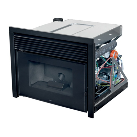
- Page 1 INSTALLATION GUIDE INSERT QBOX 70 AIR 8 M1 QBOX 60 AIR 6 M1 PART 1 - REGULATIONS AND ASSEMBLY Instructions in English...
-
Page 2: Table Of Contents
TABLE OF CONTENTS TABLE OF CONTENTS TABLE OF CONTENTS ....................II INTRODUCTION ......................1 1-WARNINGS AND WARRANTY CONDITIONS ..............2 2-INSTALLATION ......................8 3-DRAWINGS AND TECHNICAL FEATURES ..............17 4-UNPACKING ......................25 5-OVERALL DIMENSIONS ...................26 6-PRELIMINARY STEPS ....................30 7-TYPE OF FASTENING ....................33 8-ACCESSORIES ......................40 9-ASSEMBLING THE ACCESSORIES ................43 10-EXTRACTING INSERT AND LOADING PELLETS IN COLD MACHINE ......50 11-DOOR OPENING ....................56 12-ELECTRICAL CONNECTION ..................57... -
Page 3: Introduction
No part of this manual may be translated into other languages, adapted and/or reproduced, even in part, in other mechanical and/or electronic form or media, for photocopies, recordings or other, without the prior written authorisation of MCZ Group Spa. The company reserves the right to make changes to the product at any time without prior notice. The owner company reserves its rights according to law. -
Page 4: 1-Warnings And Warranty Conditions
1-WARNINGS AND WARRANTY CONDITIONS SAFETY WARNINGS • The installation, electrical connection, operating test and maintenance must only be carried out by a qualified operator. • Install the product in compliance with the laws and regulations in force. • Only use the fuel recommended by the manufacturer. The product must not be used as an incinerator. - Page 5 1-WARNINGS AND WARRANTY CONDITIONS • Do not dry laundry on the product. Any drying racks or the like must be kept at a safe distance from the product. Fire hazard. • The product maintenance operations must be exclusively carried out by a qualified operator on a yearly basis.
- Page 6 1-WARNINGS AND WARRANTY CONDITIONS • Do not allow the product to come into contact with water, it contains live electrical parts. • Do not wash the product with water (or other liquids) as they could penetrate inside the unit, damaging the electrical insulation with the risk of electrocution. •...
- Page 7 1-WARNINGS AND WARRANTY CONDITIONS • The sound pressure level of this appliance does not exceed 70 dB(A). • Live electrical parts: only power the product once it has been fully assembled. • Disconnect the product from the 230V power supply before performing any maintenance operations.
- Page 8 1-WARNINGS AND WARRANTY CONDITIONS INFORMATION: • Please contact the retailer or qualified personnel for any information, problem or malfunction. • Only use the fuel specified by the manufacturer. • When the product is switched on for the first time, it is normal for it to emit smoke due to the paint heating up for the first time. Therefore make sure the room it is installed in is well-ventilated.
- Page 9 1-WARNINGS AND WARRANTY CONDITIONS WARRANTY CONDITIONS For the duration, terms, conditions, limitations of the MCZ conventional warranty, please refer to the specific warranty card that is included with the product. Information for management of waste electrical and electronic equipment containing batteries and accu- mulators This symbol appears on the product, on the batteries, on the accumulators or on their packaging or on their documentation;...
- Page 10 1-WARNINGS AND WARRANTY CONDITIONS WARNINGS FOR THE CORRECT DISPOSAL OF THE PRODUCT The owner is the sole party responsible for demolishing and disposing of the product. This must be performed in compliance with laws related to safety and environmental protection in force in his/her country. At the end of its working life, the product must not be disposed of as urban waste.
- Page 11 1-WARNINGS AND WARRANTY CONDITIONS LEGENDA WHERE TO DISPOSE MATERIALS Metal Glass If there is any, to be disposed of separately based on the material used: Tiles or ceramics OUTER CLADDING Stone Glass ceramic (fire door): to be disposed of with inert or mixed waste If there is any, to be disposed of separately based on the material used: Tempered glass (oven door): to be disposed...
- Page 12 The EC Declaration of Conformity, the Declaration of Performance required by EU Regulation 305/2011 and all other product certification documents can be downloaded by scanning the QR code on this page (also found on the product label) or by accessing the website page www.mczgroup.com/support/mcz Having specified the above, we highlight and report that: •...
-
Page 13: 2-Installation
2-INSTALLATION The instructions in this chapter refer explicitly to the Italian installation regulation UNI 10683. In any case, always observe the regulations in force in the country of installation. PELLETS The pellet is obtained from natural dried wood sawdust (without paint). The compactness of the material is guaranteed by the lignin contained in the wood itself, without glue or binders. - Page 14 2-INSTALLATION FOREWORD The heating system (generator + combustion air supply + combustion product expulsion system + any hydraulic/aeraulic system) must be installed in compliance with the laws and regulations in force , and carried out by a qualified technician, who must issue a declaration of conformity of the system to the system manager and shall undertake full responsibility for final installation and consequent good operation of the product.
- Page 15 2-INSTALLATION MINIMUM DISTANCES Observe the distances from flammable objects (sofas, furniture, wood panelling, etc..) as specified in the following diagram. If objects considered to be particularly sensitive to heat are present, such as furniture, curtains or sofas, as a precaution, increase the stove clearances substantially to avoid possible deterioration due to the effect of heat.
- Page 16 2-INSTALLATION In any case, ensure adequate distance to facilitate access during cleaning and extraordinary maintenance. If this is not possible, it must still be possible to distance the product from adjacent walls/elements. This operation must be performed by a technician qualified to disconnect the combustion product expulsion ducts and their subsequent restoration.
- Page 17 2-INSTALLATION Below 15kW: Air duct diameter Maximum length Maximum length (smooth duct) (corrugated duct) 50mm 60mm 80mm 100mm Above 15kW: Air duct diameter Maximum length Maximum length (smooth duct) (corrugated duct) 50mm 60mm 80mm 100mm Technical Dept. - All rights reserved - Reproduction prohibited...
- Page 18 2-INSTALLATION Preparing the smoke expulsion system The combustion product expulsion system is a particularly important element for the proper operation of the appliance and must be correctly sized according to EN 13384-1. Its creation/adaptation/verification must always be carried out by a legally qualified operator and must comply with the regulations in force in the country where the appliance is installed.
- Page 19 2-INSTALLATION Chimneypot The chimneypot, meaning the end part of the flue, must meet the following characteristics: • the smoke outlet section must be at least double the internal section of the chimney; • prevent the penetration of rain or snow; •...
- Page 20 2-INSTALLATION EXAMPLES OF INSTALLATION (DIAMETERS AND LENGTHS TO BE SIZED) 1. Flue installation with hole for the passage of the pipe increased by: • minimum 100mm around the pipe if next to non-flammable parts such as cement, brick, etc.; or •...
-
Page 21: 3-Drawings And Technical Features
3-DRAWINGS AND TECHNICAL FEATURES DRAWINGS AND CHARACTERISTICS QBOX 70 AIR 8 M1 DIMENSIONS (dimensions in mm) Ø80 Technical Dept. - All rights reserved - Reproduction prohibited... - Page 22 3-DRAWINGS AND TECHNICAL FEATURES QBOX 60 AIR 6 M1 DIMENSIONS (dimensions in mm) Ø80...
- Page 23 3-DRAWINGS AND TECHNICAL FEATURES TECHNICAL CHARACTERISTICS QBOX 70 AIR 8 M1 Energy Efficiency Class Nominal output power 7.9 kW (6794 kcal/h) Minimum power output 3.6 kW (3096 kcal/h) Efficiency at Max 90.2% Efficiency at Min 92.0% Temperature of exhaust smoke at Max 157 °C...
- Page 24 3-DRAWINGS AND TECHNICAL FEATURES TECHNICAL CHARACTERISTICS QBOX 60 AIR 6 M1 Energy Efficiency Class Nominal output power 6.1 kW (5246 kcal/h) Minimum power output 3.0 kW (2580 kcal/h) Efficiency at Max 90.1% Efficiency at Min 92.0% Temperature of exhaust smoke at Max 144 °C Temperature of exhaust smoke at Min 92°C...
- Page 25 3-DRAWINGS AND TECHNICAL FEATURES ηs [%] Log wood, moisture content ≤ 25 % η η Technical Dept. - All rights reserved - Reproduction prohibited...
- Page 26 3-DRAWINGS AND TECHNICAL FEATURES ηs [%] Log wood, moisture content ≤ 25 % η η...
-
Page 27: 4-Unpacking
4-UNPACKING INSTRUCTIONS FOR PACKAGING DISPOSAL The material that the appliance’s packaging is made of must be managed correctly, in order to make collection, reuse, recovery and recycling easier, where possible. The table below illustrates the possible components that the packaging is made of, and the relative instructions for correct disposal. DESCRIPTION CODE MATERIAL SYMBOL... - Page 28 4-UNPACKING PREPARATION AND UNPACKING The product is supplied in a single package. Open the package, remove any straps, cardboard and polystyrene and take the appliance off the pallet. To remove the product from the pallet, it is necessary to remove the six screws “x”-”y”’ at the rear and remove the bracket “S”. The two screws “y”...
- Page 29 4-UNPACKING Then pull out the mobile part of the insert and remove the four screws “x” that block it to the pallet (as shown on the following pages). Once the insert has been extracted, before removing the screws, it is advisable to place a support “A” under the movable part of the insert so as to work safely.
-
Page 30: 5-Overall Dimensions
5-OVERALL DIMENSIONS EXAMPLE OF FRONTAL POSITIONING vedi disegno QBOX 70/60 vedi disegno QBOX 70/60 QBOX (Pianta) vedi disegno QBOX 70/60 vedi disegno QBOX 70/60 INSERT SUPPORT (existing or new) WALL INSULATION SAFETY DISTANCE FROM COMBUSTIBLE MATERIAL... - Page 31 5-OVERALL DIMENSIONS EXAMPLE OF PLACEMENT AT A 90° ANGLE Technical Dept. - All rights reserved - Reproduction prohibited...
- Page 32 5-OVERALL DIMENSIONS EXAMPLE OF PLACEMENT AT A 45° ANGLE...
-
Page 33: 6-Preliminary Steps
6-PRELIMINARY STEPS COMBUSTION AIR During operation a certain amount of air is drawn from the room in which the product is installed and this air must be supplemented through an external air inlet. The combustion air “B” in this product is autonomously drawn directly from the front grille, however, the user can have the air drawn from outside. - Page 34 6-PRELIMINARY STEPS • Once the box “G” is installed on the fixed part “Q”, proceed with the installation of the pipes to draw air from the outside ATTENTION! It is forbidden, in secondary use heating appliances, to use the product at maximum power for more than 2/3 hours.
- Page 35 6-PRELIMINARY STEPS Smoke duct (smoke fitting) The smoke duct is the pipe that connects the appliance to the flue. This smoke fitting must comply in particular with the following requirements: • comply with product standard EN 1856-2; • its cross-section must be of constant diameter and no less than that of the appliance outlet, from the firebox outlet up to the connection in the flue;...
- Page 36 7-PRODUCT EXTRACTION INSTALLED PRODUCT EXTRACTION In the case of interventions on the product, it can be removed from the housing. Caution! Very dangerous manoeuvre! Place a support under the product during extraction. Maintenance must only be carried out by authorised personnel. For extraction operations proceed as follows: •...
- Page 37 7-PRODUCT EXTRACTION • right and left, remove the two screws “x” and the two plates “k” • the product can be extracted It is possible to disconnect the electrical connector in order to pull the product completely out of the housing. CAUTION: THE PRODUCT MAY ONLY BE REMOVED BY A QUALIFIED TECHNICIAN WHEN THE STRUCTURE IS COLD AND THE MAINS PLUG HAS BEEN DISCONNECTED.
- Page 38 7-PRODUCT EXTRACTION To make it easier to hold, grasp the insert by the two handles “M”.
- Page 39 7-PRODUCT EXTRACTION • lift the insert • the fixed part “A” is now free and you can fasten it onto the optional support or on an existing surface (as explained in the next pages) Technical Dept. - All rights reserved - Reproduction prohibited...
-
Page 40: 7-Type Of Fastening
8-TYPE OF FASTENING HOW TO FASTEN THE INSERT It is obligatory to anchor the product to a surface during annual maintenance operations by the authorised technician, or when the fuel is loaded, the combustion chamber may be extracted from its seat with the aid of two retractable guides. The product can be anchored to an existing surface (which must have certain characteristics) or it can be fastened to the optional support. - Page 41 8-TYPE OF FASTENING Fastening to an existing surface POSITION DESCRIPTION QBOX FIXED INSERT PART EXISTING SURFACE ANCHOR BOLT (SEE PREVIOUS PAGE) If installing on an existing surface, provided with grille “G” (see next pages), it is strongly recommended to fasten it according to the diagram.
- Page 42 8-TYPE OF FASTENING Fastening to the horizontal support Place the base in the desired position (after mounting it as explained in the instructions attached to the accessory) and adjust the height with the feet (from a min. of 500 mm to a max. of 650 mm). Make sure there is a power socket behind the pedestal so that the plug is accessible after the unit has been installed.
- Page 43 8-TYPE OF FASTENING INSTALLING BOXTHERM ON EXISTING CHIMNEY If there are air inlet grids on the existing firebox, it is not necessary to close them. G = AIR INTAKE GRILLE If the existing firebox does not have any air vents, the product (QBOX) has feet at the bottom that in any case allow air to pass through (as shown on the next page).
- Page 44 8-TYPE OF FASTENING FASTENING TO THE EXISTING FIREBOX WITHOUT AIR OPENINGS If the existing firebox does not have any air openings, the fixed part “A” of the insert is fitted with four feet “v” (standard) which ensure that the product is raised above the existing firebox. This ensures air circulation for proper product operation. Caution! After installing the product, whether on an existing chimney or a new one, try to extract the insert a few times before completing the cladding to ensure that there are no obstacles or difficulties when extracting it.
- Page 45 9-ACCESSORIES 4-SIDED FRAME The product comes standard with the three-sided frame “Y”. In the case of installation without panelling, the lower frame “K” can be purchased to make the standard 4-sided frame Support Used to position the product at the required height without using an existing surface. Technical Dept.
- Page 46 10-LOADING PELLETS The pellets are loaded into the hopper via the upper drawer. For loading operations proceed as follows: • open the drawer “L” using the cold handle “Z” supplied. The guides of the tray have an end-of-travel that block the mobile part when extracted completely (approximately 30 cm).
- Page 47 10-LOADING PELLETS When finished, close drawer “L” all the way. We recommend you try different ways of loading to understand how may actions are required with tool “B”. When it becomes difficult to unload the pellets, this means that the hopper is full. After filling up the tank, close the drawer, even if it is full of pellets.
-
Page 48: 11-Door Opening
11-DOOR OPENING DOOR OPENING To open the product door “C”, fit the cold handle “Z” into the hole in the handle and pull it towards you. Caution! The firebox door must be closed properly for the stove to work correctly. The door should only be opened with the product switched off and cold. -
Page 49: 12-Electrical Connection
12-ELECTRICAL CONNECTION ELECTRICAL CONNECTION First connect the power cable to the rear of the product and then to a wall socket, which must always remain accessible. Should this not be possible, during installation insert suitable devices for disconnection from the power mains, in compliance with national electrical installation standards. -
Page 50: 13-Cladding
13-CLADDING SETTING UP THE CLADDING All product functionalities must be tested before being clad. The company cannot be held liable for any damage to the cladding should operating anomalies arise, which were not ascertained before the cladding was applied to the product. IT IS OBLIGATORY to check seal of all piping the smoke goes through (smoke fitting, gaskets and insert in the flue) before installing the cladding. - Page 51 13-CLADDING The machine must be insulated (panel K) so as not to receive air from the hood “Z” and counter- hood “Y”. The ventilation air “3” must only come from the bottom. 2 - rigid or solid filler panel (not mesh) 1 - a grille can be used to vent the hot air accumulated at the top of the product Technical Dept.
- Page 52 MCZ GROUP S.p.A. Via La Croce n°8 33074 Vigonovo di Fontanafredda (PN) – ITALY Telephone: 0434/599599 a.s. Fax: 0434/599598 Internet: www.mcz.it e-mail: mcz@mcz.it 8902313900 REV. 2 14/03/2024...
Need help?
Do you have a question about the QBOX 70 AIR 8 M1 and is the answer not in the manual?
Questions and answers