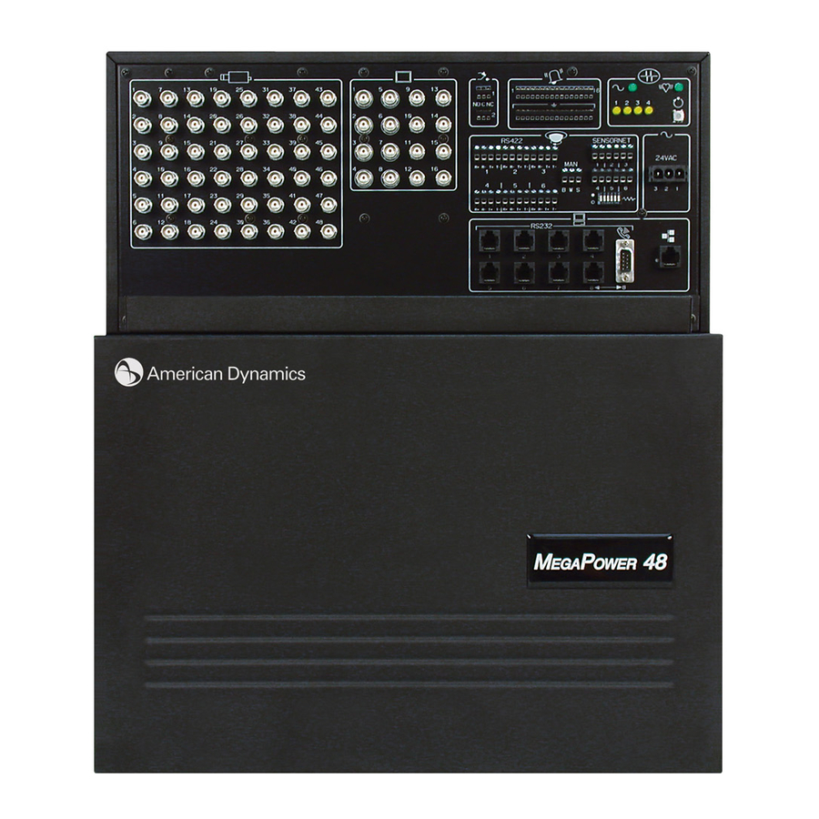
American Dynamics MegaPower 48 Plus Installation Manual
Matrix switcher/controller
Hide thumbs
Also See for MegaPower 48 Plus:
- Installation and operation manual (44 pages) ,
- Datasheet (4 pages) ,
- Specifications (15 pages)
Table of Contents
Advertisement
Advertisement
Table of Contents

Related Manuals for American Dynamics MegaPower 48 Plus


Summary of Contents for American Dynamics MegaPower 48 Plus
- Page 1 MegaPower Installation Manual...
-
Page 2: Fcc Compliance
FCC Compliance This equipment has been tested and found to comply with the limits for a Class A digital device, pursuant to Part 15 of the FCC Rules. These limits are designed to provide reasonable protection against interference when the equipment is operated in a commercial environment. -
Page 3: Table Of Contents
RS232 Peripheral Interface Port Connection ......................30 Drawing 19: Connections to PC and External Modem ....................31 Drawing 20: Patch Panel to AD2096A Alarm Interface Unit to Alarm Contact ............32 Drawing 21: Video Recorder Control via ADCC1100 Keyboard ................. 33... - Page 4 RS232 Connections in a Multi-Matrix System ........................51 PC Connection in a Multi-Matrix System ..........................51 Manchester, SensorNet and SEC-RS422 Connections in a Multi-Matrix System ............51 Alarm Connections in a Multi-Matrix System ........................51 Control Addressing Quick Look-Up Table .......................... 54 MegaPower 48+ System Troubleshooting ..........................
-
Page 5: Introduction
The unit can also be mounted behind other equipment in the rear of a rack at 90° to conserve space for other products or it can be rack mounted at other angles to facilitate easy cable connections. -
Page 6: Mechanical Installation
Patch Panel Diagnostics Section If normal operation is indicated, call a monitor with a system keyboard, and then call a camera to the called monitor. If the event of absent or abnormal diagnostic signals, power the system down and re-check system connections. If necessary, consult Troubleshooting on page 55. -
Page 7: Drawing 1: Wall Bracket Assembly
Installation Manual Drawing 1: MegaPower 48+ Mechanical Installation Wall Bracket Assembly... -
Page 8: Drawing 2: Patch Panel And Wall Bracket Assembly
MegaPower Drawing 2: MegaPower 48+ Mechanical Installation Patch Panel and Wall Bracket Assembly... -
Page 9: Drawing 3: Cable Management Bracket - Tie Wraps And Clips
Installation Manual Drawing 3: MegaPower 48+ Mechanical Installation Cable Management Bracket - Tie Wraps and Clips... -
Page 10: Drawing 4: Patch Panel To Transformer Cable
MegaPower Drawing 4: AC Power Section Patch Panel to Transformer Cable... -
Page 11: Drawing 5: Attaching The Main Electronics Unit (Meu)
Installation Manual Drawing 5: MegaPower Mechanical Installation Attaching the Main Electronics Unit (MEU) -
Page 12: Patch Panel Overview
Note: either the DB9 connector or RJ45 jack number 8 of the RS232 section can be used as an alternative port for an external device - either connector is recognized as Port 8 by the MegaPower 48+ system, but... -
Page 13: Drawing 6: Megapower 48 Patch Panel
Installation Manual Drawing 6: MegaPower 48+ Patch Panel... -
Page 14: System Programming
Connections are made to and from various system devices and the MegaPower 48+ patch panel. In some cases, simple, direct connections can be made from device to panel. In other cases, system accessories are utilized to implement appropriate system operation. -
Page 15: Drawing 7: Patch Panel To Video Inputs And Video Outputs
Installation Manual Drawing 7: Patch Panel to Video Inputs and Video Outputs... -
Page 16: Cable Networks
• Star – in a star configuration, up to four branches connect to a central hub location (typically a J-Box or other data distribution unit). Domes can attach with separate cables (daisy chain style) as shown in Fig.C, or, with a single continuous cable (backbone style) as shown in Fig. -
Page 17: Drawing 8: Patch Panel To Ad1641 Receiver To Ad1240 Pan/Tilt
Installation Manual Drawing 8: Manchester Communications Patch Panel to AD1641 Receiver to AD1240 Pan/Tilt... -
Page 18: Drawing 9: Patch Panel To Ad2083-02B Code Translator To Integrated Dome
MegaPower Drawing 9: Manchester Communications Patch Panel to AD2083-02B Code Translator to Integrated Dome... -
Page 19: Drawing 10: Patch Panel To Ad1691 Code Distributor To Integrated Dome
Installation Manual Drawing 10: Manchester Communications Patch Panel to AD1691 Code Distributor to Integrated Dome... -
Page 20: Drawing 11: Patch Panel To Ad2031 Switcher Follower To Audio Circuit
MegaPower Drawing 11: Manchester Communications Patch Panel to AD2031 Switcher Follower to Audio Circuit... -
Page 21: Star Connections/Ad1691 Code Distributor
10 domes. All 48 video inputs can be accommodated using six 10-position J-boxes, with each J- Box connected to six domes. See Drawing 13, Page 23 for a typical connection of the patch panel to a 10-position J- box. -
Page 22: Drawing 12: Patch Panel To 6-Position J-Box To Integrated Dome
MegaPower Drawing 12: Sensornet Communications Patch Panel to 6-Position J-Box to Integrated Dome... -
Page 23: Drawing 13: Patch Panel To 10-Position J-Box To Integrated Dome
Installation Manual Drawing 13: RS422 Communications Patch Panel to 10-Position J-Box to Integrated Dome... -
Page 24: Rs232 Communications
The ADTTE Touch Tracker keyboard connects to an EIM module via an 8 conductor, 14 foot modular cable with RJ45 plugs. MegaPower 48+ RS232 ports connect to the EIM module via an 8 conductor cable with an RJ45 plug at one end, and a DB9M connector at the other end. -
Page 25: Drawing 14: Patch Panel To Adcc1100 Keyboard
Installation Manual Drawing 14: RS232 Communications Patch Panel to ADCC1100 Keyboard... -
Page 26: Drawing 15: Patch Panel To Adcc0200 And Adcc0300 Keyboards
MegaPower Drawing 15: RS232 Communications Patch Panel to ADCC0200 and ADCC0300 Keyboards... -
Page 27: Drawing 16: Patch Panel To Ad2079 And Ad2088 Keyboards
Installation Manual Drawing 16: RS232 Communications Patch Panel to AD2079 and AD2088 Keyboards... -
Page 28: Drawing 17: Patch Panel To Adtte Keyboard
MegaPower Drawing 17: RS232 Communications Patch Panel to ADTTE Keyboard... -
Page 29: Drawing 18: Patch Panel To Ad1981 Port Expander To System Keyboards
Installation Manual Drawing 18: RS232 Communications Patch Panel to AD1981 Port Expander to System Keyboards... -
Page 30: Pc Connection
An RS232 connection can be made between the MegaPower 48+ and a PC by connecting a seven foot (2.2 m) modular cable with RJ45 plugs to the DB9M on one of the PC’s COM ports using a converter with an RJ45 receptacle and a DB9F connector. -
Page 31: Drawing 19: Connections To Pc And External Modem
Installation Manual Drawing 19: RS232 Communications Connections to PC and External Modem... -
Page 32: Drawing 20: Patch Panel To Ad2096A Alarm Interface Unit To Alarm Contact
MegaPower Drawing 20: RS232 Communications Patch Panel to AD2096A Alarm Interface Unit to Alarm Contact... -
Page 33: Drawing 21: Video Recorder Control Via Adcc1100 Keyboard
Installation Manual Drawing 21: RS232 Communications Video Recorder Control via ADCC1100 Keyboard... -
Page 34: Drawing 22: Ethernet Connections To A Pc
MegaPower Drawing 22: Ethernet Connections to a PC... -
Page 35: Direct Alarm And Relay Connections
AD2096A Alarm Interface Unit, 192 dome alarms (up to 48 domes, with four alarm contacts per dome), and up to 48 video loss alarms that are generated when a loss of video sync is detected at a video input. -
Page 36: Drawing 23: Patch Panel Alarms And Relay Sections
MegaPower Drawing 23: Patch Panel Alarms and Relay Sections... -
Page 37: Multi-Matrix Configurations
AD2096A Alarm Interface Unit, can be included in a system. Mode 2 Configuration A Mode 2 configuration has a primary matrix and a maximum of four secondary units, with 12 monitor outputs from each secondary matrix connected to 12 video inputs on the primary matrix. -
Page 38: Mechanical Installation Of Multiple Matrices
In a multi-matrix system, matrices can be connected together via Ethernet. All ethernet connections should be made with Cat 5 twisted pair cable with a maximum length of 300 feet. If longer connections are required, hubs and repeaters are available. - Page 39 In a multi-matrix system with more than two matrices, matrices must be connected together via a network switch as shown in the figure below. It is preferable to use a true network switch rather than a hub as a switch only sends data to the relevant port connection while a hub will copy the data to all ports.
-
Page 40: Video Connections In A Multi-Matrix System
In all following sections, the maximum number of trunk video connections are shown and by connecting in this manner, the maximum number of full cross point switched monitor outputs can be achieved. It should be noted that if the number of full cross point switched monitor outputs is lower, only this number of trunk video connections need to be made. - Page 41 Mode 1: Primary Matrix with 2 Secondary Matrices Consult the figure below in order to connect video inputs and outputs to the system. The 16 monitor outputs from each secondary matrix must be connected to 16 video inputs on the primary matrix. Sixteen full cross point switched monitor outputs are available by connecting monitors to video outputs 1-16 on the primary matrix.
- Page 42 Mode 1: Primary Matrix with 3 Secondary Matrices Consult the figure below in order to connect video inputs and outputs to the system. The 16 monitor outputs from each secondary matrix must be connected to 16 video inputs on the primary matrix. Sixteen full cross point switched monitor outputs are available by connecting monitors to video outputs 1-16 on the primary matrix.
-
Page 43: Mode 2 Configurations
Mode 2: Primary Matrix with 1 Secondary Matrix Consult the figure below in order to connect video inputs and outputs to the system. Monitor outputs 4-15 from the secondary matrix must be connected to video inputs 1-12 on the primary matrix. - Page 44 8 video inputs on the primary matrix. Eight full cross point switched monitor outputs are available by connecting monitors to video outputs 1-8 on the primary matrix. Monitors can also be connected to monitor outputs 1-7 on each secondary matrix. These monitors can display video inputs from that secondary unit only.
- Page 45 Installation Manual Consult the figure below in order to connect video inputs and outputs to the system. Monitor outputs 8-15 from each secondary matrix must be connected to 8 video inputs on the primary matrix. Eight full cross point switched monitor outputs are available by connecting monitors to video outputs 1-8 on the primary matrix.
- Page 46 Mode 3: Primary Matrix with 5 or 6 Secondary Matrices Consult the figures on page 52 and 53 in order to connect video inputs and outputs to the system. Monitor outputs 8-15 from each secondary matrix must be connected to 8 video inputs on the primary matrix.
-
Page 47: Mode 3 Configurations
Keyboard and Port Expander Connection Keyboards can be connected to any RS232 port in a multi-matrix system. Therefore, in a Mode 3 configuration with six secondary matrices, up to 56 keyboards can be connected (without using port expanders). Any of these keyboards can be used to control any component in the system—keyboards connected to a secondary matrix are NOT limited to... -
Page 48: Megapower Tm
The use of port expanders is also supported in multi-matrix systems, enabling up to four keyboards to be connected to any one RS232 port. This means up to 32 keyboards can be connected to any matrix, and that in a Mode 3 configuration with six secondary matrices, up to 224 keyboards can be connected. - Page 49 An AD2096A Alarm Interface Unit (AIU) can be connected to any RS232 port in a multi-matrix system. Each AD2096A can be connected with up to 64 alarm contacts, and a maximum of eight units can be connected to the system (i.e., maximum 512 RS232 alarm inputs).
-
Page 50: Pc Connection In A Multi-Matrix System
MegaPower 48+ embedded software and system setup software provide the user with a system option to enable one Peripheral Interface Port (PIP). This can be any RS2332 port in a multi-matrix system. See page 30 for more details. PC Connection in a Multi-Matrix System... -
Page 51: Rs232 Connections In A Multi-Matrix System
For example If camera 49 is connected to secondary matrix B, then the control connection must also be made to matrix B and the address would be “1” as the camera is connected to port 1 on matrix B. - Page 52 MegaPower...
- Page 53 Installation Manual...
-
Page 54: Control Addressing Quick Look-Up Table
MegaPower Control Addressing Quick Look-Up Table... - Page 55 Installation Manual Directive (LVD) 73/23/EEC. The equipment was tested in a typical configuration.
- Page 56 MegaPower...
-
Page 57: Declaration Of Conformity
Composite Output Voltage ......≤ 0.5 dB Average Output Voltage ......± 250 mV Cross Talk ..........Adjacent Channel: -55 dB typical at 3.58 to 4.43 Mhz Input to Input: - 70 dB typical at 3.58 to 4.43 Mhz Differential Phase ........≤ 2.0 % Differential Gain ........ -
Page 58: Megapower 48+ Product Specifications
Character Attributes ........Character Intensity, 8 levels Text Background: transparent Character Sets .......... English (standard) Display Area Positioning: ......X direction – 10 µsec after the end of the horizontal sync pulse Y direction – 29 lines from the end of vertical sync pulse System Communications External Device Communications S-Net 485 Ports (6) ........ - Page 59 • Power LED (viewable on patch panel) • Four Diagnostic LEDs (viewable on patch panel) • +/- Voltage LEDs viewable on patch panel • Peripheral control of SensorNet, SEC-RS422, RS232 and AD Manchester devices without the use of any external...
- Page 60 MegaPower interface units Product Codes VR48NC ............ 48 x 16 Matrix Switch with no Controller VR48KB ............ 48 x 16 Matrix Switch with AD2088 VR48TT ............. 48 x 16 Matrix Switch with ADTTE Compatible Product Listing Non-CE Approved CE Approved...
- Page 61 Installation Manual...
- Page 62 MegaPower...
- Page 63 Installation Manual...
- Page 64 Please visit our website for more information www.americandynamics.net © 2004 American Dynamics Product specifications subject to change without notice Certain product names mentioned herein may be trade names MP-48INST-HB-2 and/or registered trademarks of other companies...
Need help?
Do you have a question about the MegaPower 48 Plus and is the answer not in the manual?
Questions and answers