
Related Manuals for Simrad B&G RS100


Summary of Contents for Simrad B&G RS100
- Page 1 RS100/RS100-B V100/V100-B USER MANUAL ENGLISH RS100/RS100-B V100/V100-B www.simrad-yachting.com | www.bandg.com...
- Page 2 Copyright Copyright © 2021 Navico Holding AS. Warranty The warranty card is supplied as a separate document. In case of any queries, refer to the brand website of your unit or system: • www.simrad-yachting.com • www.bandg.com Preface | Installation Manual...
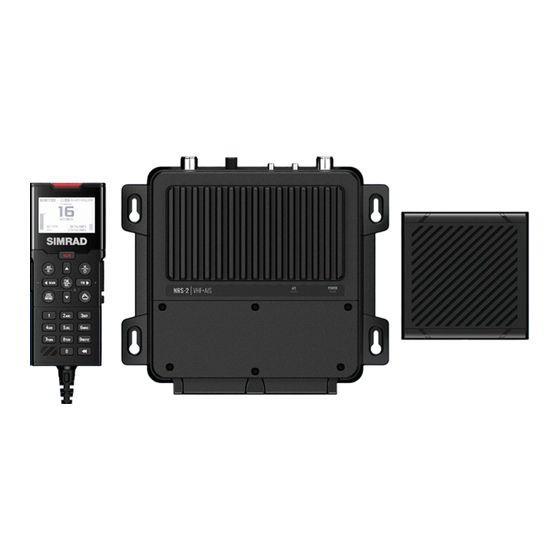
- Page 3 • NRS-1 Marine VHF Radio Processor • HS100 Wired Handset SIMRAD • SP100 Wired Speaker SIMRAD® RS100-B Blackbox VHF & AIS Radio System • NRS-2 Marine VHF Radio & AIS Class-B Processor • HS100 Wired Handset SIMRAD® • SP100 Wired Speaker B&G®...
- Page 4 Radio Operator’s license. Contact the appropriate licensing authority in your country. If you’re unsure who to contact, consult your Simrad or B&G dealers. • A valid ATIS ID number must be entered into this radio before ATIS functions can be used.
- Page 5 Regulatory compliance statements European Union Navico declare under our sole responsibility that the RS100, RS100- B, V100, and V100-B conforms with the requirements of Directive 2014/53/EU (RED). HS40 and H60 Wired Handset complies with CE under EMC Directive 2014/30/EU. The relevant Declaration of conformity is available in the product’s section at the following website: •...
- Page 6 United States Part 15 of the FCC Rules. Operation is subject to the following two conditions: (1) this device may not cause harmful interference, and (2) this device must accept any interference received, including interference that may cause undesired operation. ⚠Warning: The user is cautioned that any changes or modifications not expressly approved by the party responsible...
- Page 7 FCC Part 18 compliance statement for cradle charger (BC-12) This device complies with Part 18 of the FCC Rules. ⚠Warning: Changes or modifications not expressly approved by the party responsible for compliance could void the user’s authority to operate the product. ¼...
- Page 8 suivantes: • L’appareil ne doit pas produire de brouillage. • L’appareil doit accepter tout brouillage radioélectrique subi, même si le brouillage est susceptible d’en compromettre le fonctionnement. Innovation, Science and Economic Development Canada (ISED) This equipment complies with IC RSS-102 radiation exposure limits set forth for an uncontrolled environment.
- Page 9 Navico® is a registered trademark of Navico Holding AS. B&G® is a registered trademark of Navico Holding AS. SIMRAD® is a registered trademark of Kongsberg Maritime AS, Licensed to Navico Holding AS. NMEA® and NMEA 2000® are registered trademarks of the National Marine Electronics Association.
- Page 10 • A valid USER MMSI must be entered into this radio before DSC functions can be used. • Many countries do not have radio repeaters that support DSC message relaying. However DSC can still be useful for direct ship- to- ship communication, where the other vessel is also equipped with a DSC capable radio.
- Page 11 By law, you are not able to change your MMSI once it is entered into the radio. This is why there is a confirmation screen when entering the MMSI. If you need to have the MMSI in the radio changed, the radio must be taken back to your Simrad or B&G dealer. •...
-
Page 12: Table Of Contents
Contents 16 Getting started 17 How to display and navigate menus 19 LCD functions 20 Keypad functions 23 Wired Handset Numeric Keys 25 Radio menus 25 Menu tree 27 Scan 28 Watch 29 Voice recorder 29 Display 31 Radio setup 36 DSC/ATIS setup 38 AIS setup 41 Alarms... - Page 13 59 Fog Horn, Intercom, and Hailer 59 Using the FOG Horn 60 Using the INTERCOM (IC) 60 Using the HAILER 60 Using ANNOUNCE 61 My channels 62 Shortcuts 62 Add/Edit Shortcuts 63 MOB and NAV functions 63 Man Over Board (MOB) 64 Navigation Function (NAV) 65 Installation 65 What’s in the box...
- Page 14 87 Power LED 87 AIS LED (NRS-2 only) 87 AIS Pop-up warning messages (NRS-2 only) 88 Troubleshooting 93 RS100/B, V100/B Specifications 93 System features 93 Technical 95 VHF Transceiver 95 VHF Transmitter 95 VHF Receiver 96 AIS (Class-B) (NRS-2 only) 96 Built-in GPS Receiver 96 Wireless specifications 97 HS100 / H100 - Fixed handset...
-
Page 15: Getting Started
Getting started The RS100 / V100 system provides the following features: • Up to 4 wired alphanumeric handset stations • Up to 4 wireless handsets (HS40/H60) • 4 configurable 4 W wired speaker outputs • Built-in GPS processor for connection with an external GPS antenna •... -
Page 16: How To Display And Navigate Menus
How to display and navigate menus Split screen display: Main Menu - select an option from the Menu to setup or modify settings. Split screen display: Channel region - displays the radio frequency information. Scroll bar indicates additional options above or below displayed Menu text. - Page 17 Symbols Descriptions Radio is transmitting Receiver busy with incoming signal Low Transmit power selected (1W) High Transmit power selected (25W) Current channel is Duplex (Simplex when OFF) Current channel is receive only Local mode enabled (used when in areas of high radio traffic, i.e.
-
Page 18: Lcd Functions
LCD functions Radio is Transmitting (TX) mode. Will change to BUSY when receiving Missed call in the DSC call log Channel is set to high power transmit Low vessel voltage alert Weather alert function is enabled (USA models) Sensitivity mode is set to LOCAL AIS receiver is enabled (NRS-2 only) Internal GPS is enabled, with 3D fix DSC functionality is enabled, but auto-switch is OFF... -
Page 19: Keypad Functions
Keypad functions 16/9 SCAN MENU VOL-SQL WXYZ PQRS Distress A Distress call is broadcast to all DSC equipped radios, so will create an alarm on every DSC radio within range. If position information is available it will be included in the transmission. Short press to commence a distress call. - Page 20 ¼ Note: The radio system can only be turned ON from any Fixed Handset (F1-F4). ¼ Note: When the system is ON: • The system can only be turned OFF from the Fixed Handset 1 (F1); • Long presssing the X key from the handset (F2-F4) will turn that handset OFF;...
- Page 21 ¼ Note: Some channels allow only low power transmissions initially, but can be overridden to high power by pressing (and holding) H/L after depressing PTT. Keep the H/L key pressed down after releasing the PTT key, if wanting to transmit again on high power.
-
Page 22: Wired Handset Numeric Keys
/ TRI / + • Menu mode: Short press to move the cursor one character to the right • Normal radio mode: Short press to start DUAL WATCH or TRI WATCH (if ‘watch’ channel set). Refer to “Watch” on page 28 for more details. Long press to set the current channel as the watch channel. - Page 23 Mode Short press Long press Normal Hailer mode menu Data input (blank character/space) Intercom Call all IC stations All PA announce tone Normal Horn mode menu Data input Intercom Direct call to Handset-1 Normal Alarms config. menu Data input 2, A, B, C Intercom Direct call to Handset-2 Normal...
-
Page 24: Radio Menus
Radio menus Menu tree Long press the DSC/MENU key to open the main Menu page. The following shows the available menu and submenu options: ¼ Note: Main (first) level and 2nd level only. Key definition: ) - a checkbox in the menu option. ¼... - Page 25 SENSITIVITY (DISTANT/LOCAL) US/CAN & (USA/INT’L/ INT country CANADA) modes POWER OUTPUT (HIGH/LOW) CH NAME (>) KEY BEEP (0-10) UNITS (>) HANDSET SPEAKER (ON/OFF) Radio setup EXTERNAL SPEAKER (>) (>) COM PORT (>) TIME (>) VESSEL CALL SIGN (>) AUTO POWER ON (AUTO/MANUAL) (NONE/5 MINS MENU TIMEOUT...
-
Page 26: Scan
AIS FUNCTION NRS-2 only SILENT MODE (ON/OFF) NRS-2 only AIS DISPLAY (MMSI/NAME) NRS-2 only AIS setup (>) NRS-2 only TCPA (>) NRS-2 only CONFIG VESSEL (>) NRS-2 only GPS ALERT (>) US/CAN WX ALERT (>) country Alarms modes DSC ALARM (>) CPA ALARM (>) -
Page 27: Watch
and resume the scan. The direction selected determines if the scan goes up or down the channel numbers (ie ‘forward’ or ‘reverse’). If it is still busy when the scan completes a full cycle, it will stop again at this channel. Note that it is not possible to skip over the priority channel. -
Page 28: Voice Recorder
¼ Note: Also accessible by short press of the TRI key. • Without a watch channel the radio will go to DUAL WATCH, where the channels ‘watched’ are the current channel and the priority channel (the distress channel, CH16 for most countries). •... - Page 29 Use this menu to have backlighting adjustments synchronized with other connected devices. Network group Set this value to the same as other Simrad/B&G devices on the NMEA 2000 network. To keep backlight control independent, set to a value not used elsewhere.
-
Page 30: Radio Setup
Network min level Select a minimum level. This is to allow the backlight is always on if the network level is set too low. Select between 0 to 5. Network max level Select a maximum level. This is to ensure the backlight is never too bright if the network level is set too high. - Page 31 Power output Select to toggle between High power (25 W – indicated by ) or Low power (1 W – indicated by ) transmission power for the entire channel bank. Low power transmission draws significantly less current (about 1/4) from the battery, so is recommended for short range communication and where battery capacity is limited.
- Page 32 Speaker config You can associate one or more External speakers to any Fixed handset. For each of the four External speakers select a Handset to be associated with it. • Press , and to select the HANDSET column and press OK/HL.
- Page 33 GPS source ¼ Note: This function is also available as a Shortcut. Depending on your radio blackbox model, you can select between a Networked GPS source (NRS-1) or Internal GPS source (NRS-1 and NRS-2). ¼ Note: A valid GPS source is required for DSC and AIS functions to operate.
- Page 34 COM port The NMEA 0183 COM PORT is used by the radio to send and receive data. This is a global setting for the radios GPS, DSC and AIS functions. Supported NMEA 0183 messages are listed in the Specifications section of this manual. Baud rate Select 38400, or 4800 BAUD.
-
Page 35: Dsc/Atis Setup
DO NOT enter a random ‘made up’ number. ¼ Note: Contact a Simrad or B&G dealer if you need to change your MMSI after initial input. ATIS function (EU country mode only) ATIS must be enabled when navigating inland waterways in signatory countries of the RAINWAT agreement. - Page 36 DO NOT enter a random ‘made up’ number. ¼ Note: Contact a Simrad or B&G dealer if you need to change your ATIS ID after initial input. Individual acknowledge The radio can be configured to automatically acknowledge an incoming ‘individual’...
-
Page 37: Ais Setup
With AUTO SWITCH set to OFF: • The following symbol will be displayed: • Any channel change request will require manual confirmation. Test acknowledge The radio can be configured to automatically acknowledge an incoming test call, or require manual intervention: Auto The DSC test call is automatically acknowledged after a 10 second delay. - Page 38 When ON, AIS transmissions are paused, this is indicated by will still receive AIS traffic. Select OFF to resume AIS transmit mode. Silent mode can also be activated from your Simrad/B&G MFD, or by hardwired switch connected to the NRS-2 Blackbox AUX terminal.
- Page 39 Ship name Enter the ship’s name; maximum 20 alpha-numeric characters. Call sign Enter your VHF radio call sign – this must be supplied from your local radio spectrum authority. Will automatically show if it was entered during the initial startup of the radio. MMSI Your DSC MMSI number.
-
Page 40: Alarms
Once all Vessel Details fields are entered and saved, select View Vessel Details to view the AIS static data details. ¼ Note: Contact a Simrad or B&G dealer if you need to change the vessel details after saving. Alarms The radio provides audible and visual alerts for critical functions. Alert settings can be adjusted to you convenience. - Page 41 Screen flash Select between ON and OFF S.A.M.E. Code The NOAA All Hazards Weather Radio Service (NWR) works in conjunction with the Emergency Alert System (EAS) to issue weather alerts for specific geographic areas or weather warnings. It uses a digital encoding system known as Specific Area Message Encoding (SAME) to broadcast these alerts.
-
Page 42: Handsets
CPA alert function If set to OFF, the radio will not respond to T/CPA alerts including audible alarm, screen message, and screen flash. Alert volume Select between HIGH, LOW, or OFF Screen flash Select between ON or OFF Ignore function When an T/CPA Alert is activated, you have the following options: •... - Page 43 • Wireless handsets must initially be paired with the blackbox radio (the Host) through the pairing process. Refer to “Pair a wireless handset” for more details. • Handsets are provided a handset identification number which is displayed at the top of its screen above the channel number. F1-4, W1-4.
-
Page 44: Using The Wireless Handset
Locate a WHS To locate an already paired wireless handset: 1 Select LOCATE A WHS from the WIRELESS HANDSET submenu. 2 Use to select the handset you wish to locate. 3 Press OK. The handset to be located will commence beeping for 30 seconds if it is turned ON within the wireless range. -
Page 45: Diagnostics
When the wireless handset is not in use, it should be placed back into the charger cradle. The Wireless handset is charged when placed in the cradle via the built-in contactless inductive charging system. Long press the X key to turn OFF the wireless handset. The handset will automatically turn OFF after 90 seconds of no communication with the host radio. - Page 46 • DSC FUNCTION: Shows result of DSC hardware self-test performed at power-on. OK if passes, otherwise FAIL – refer to troubleshooting guide. • HANDSET STATUS: Fixed Handset installed and turned ON Fixed Handset installed and turned OFF This handset Wireless Handset installed and turned ON NMEA2000 status ¼...
-
Page 47: Reset
• AIS-RX: Shows result of AIS receiver hardware self-test performed at power-on. OK if passes, otherwise FAIL. • CH-A RX:, CH-B RX: Displays number of AIS messages received by the dual-channel receiver. • AIS-TX: Shows result of AIS transmitter hardware self-test performed at power-on. -
Page 48: Dsc Call Menu
DSC call menu Digital Selective Calling (DSC) is a semi-automated method of establishing VHF, MF, and HF radio calls. One big advantage that DSC enabled radios offer is that they can receive calls from another DSC radio without being on the same channel as the calling radio. Short press the DSC / MENU key for the following options: •... - Page 49 Below are the nature of distress options available in the Distress menu: • UNDESIGNATED • FIRE • FLOODING • COLLISION • GROUNDING • CAPSIZING • SINKING • ADRIFT • ABANDONING SHIP • PIRACY • MAN OVERBOARD ¼ Note: Undesignated is the default setting. An undesignated distress call can be sent by lifting the DISTRESS cover and long pressing the Distress key.
- Page 50 Alternatively, to cancel the Distress Call, press the X key and then the DSC/MENU key to confirm. This will send a DISTRESS CANCEL call. You must then press the PTT key and announce the reason for the cancellation. GROUP Used to place a call to a known group of vessels, all using the same ‘Group Call ID’...
-
Page 51: Track Buddy
• CONTACTS: an existing vessel already saved in your CONTACTS list DSC TEST Used to place a TEST call to a single other vessel. The call can be initiated by selecting: • MANUAL: enter a new vessel’s MMSI • RECENT: select a vessel in the RECENT list •... -
Page 52: Contacts
START TRACKING / STOP TRACKING ¼ Note: This feature is also available as a Shortcut Select START TRACKING to initiate tracking of buddies in the Buddy list that have been set to tracking ON. The radio will show a screen indicating which buddy is being called. If there is no acknowledgement, the radio will retry the call after a few seconds. - Page 53 Press OK to select a category: Press DSC/MENU for options: You have several options depending on the selected Call Log: • RESEND to resend the SENT Call • POS REQUEST to request a position form the vessel • DETAILS to view the message details •...
-
Page 54: Ais Menu (Nrs-2 Only)
AIS menu (NRS-2 only) ⚠Warning: Valid GPS data must be entered into this radio before the AIS functions can be used. The plotter PPI function will not display targets accurately with incorrect GPS data. ⚠Warning: Take note that not all vessels will have an AIS transceiver installed or turned on, so will NOT be taken into consideration for Collision Avoidance. -
Page 55: Ais Information And Display
Silent mode can be selected on the radio via the AIS Setup menu > SILENT MODE; or via a connected compatible Simrad MFD. AIS information and display AIS vessel information can be displayed on the radios LCD screen: 1 Short press the AIS/IC key to display the AIS plotter screen. - Page 56 6 Press the OK/HL key to view full details of the highlighted target such as MMSI, Vessel name, distance, bearing, heading, ROT, COG, SOG, status and other vessel information that maybe available: T/CPA Approach Screen 1 When in AIS mode, short press the AIS/IC key again to toggle between the standard AIS screen and the T/CPA Approach screen.
- Page 57 Plotter symbols and meanings Symbols Descriptions Your vessel is always in the center of the plotter screen, represented by a solid circle with a small protruding line indicating your bearing with respect to North. A diamond shape represents all other vessels or targets displayed on the plotter screen.
-
Page 58: Fog Horn, Intercom, And Hailer
Fog Horn, Intercom, and Hailer ¼ Note: An appropriate Hailer speaker must be connected to the Hailer wiring before the HAILER or FOG HORN functions can be used. Using the FOG Horn The FOG horn will sound certain international standard fog horn tones through the Hailer speaker depending on the mode selected. -
Page 59: Using The Intercom (Ic)
Using the INTERCOM (IC) Intercom mode allows you to talk directly other handsets in the system. You can choose to talk to All installed handsets, a preconfigured group of handsets or select individual handsets. ¼ Note: The Intercom mode works only when more than one FHS or WHS are installed. -
Page 60: My Channels
My channels The MY CHANNELS page is accessed by long pressing the numeric 9 key. This page provides a shortcut to frequently accessed channels. The first time this page is opened, the entire channel list is shown so that the desired shortcut channels can be selected. Subsequent opening of this page will show a list of only the selected channels. -
Page 61: Shortcuts
Shortcuts The Shortcuts page is accessed by long pressing the VOL/SQL selector key. This page is provided as a shortcut to frequently accessed functions. The shortcut options available on this page are subject to selections made in ADD/EDIT SHORTCUTS. Add/Edit Shortcuts Long press the VOL/SQ selector key. -
Page 62: Mob And Nav Functions
MOB and NAV functions Man Over Board (MOB) An MOB is generated by press and hold SCAN and TRI keys together. The screen will change to MOB navigation mode to help navigate back to the MOB location: • DST shows the current distance to MOB waypoint. •... -
Page 63: Navigation Function (Nav)
• KEEP CURRENT MOB: to return to normal operation mode without cancelling MOB navigation. • CANCEL CURRENT MOB: to cancel current MOB navigation and return to normal radio operation mode. Navigation Function (NAV) Long press 6 to enter the NAV (Navigation) mode. The screen will change to navigation mode displaying the vessel’s current SOG and Press the X / POWER key to exit NAV mode and return to normal radio operation mode. -
Page 64: Installation
¼ Note: Systems utilizing the NRS-2 Blackbox requires an additional VHF/AIS antenna which is not provided. Consult your Simrad or B&G dealer for advice on selecting the correct antenna for your installation. Blackbox with the following items: Description # of... - Page 65 Fixed Handset with the following items: Description # of items HS100 or H100 Fixed Handset (FHS) CR100 FHS Mounting Cradle AP-3 Accessory pack: FHS cradle mounting kit S/S Pan-head self-tapping screw (M4 x 25) S/S Pan-head machine screw (M4 x 25) S/S flat washer (M4) S/S split washer (M4) S/S hex nut (M4)
-
Page 66: Mounting Guidelines
S/S flat washer (M3) S/S split washer (M3) S/S hex nut (M3) Warranty card GPS-500 antenna with the following items (NRS-2 Systems only): Description # of items GPS-500 GPS antenna See documentation provided in the GPS-500 Mounting guidelines Choose the mounting location carefully, ensuring there are no hidden electrical wires or other parts behind the panel before you drill or cut. - Page 67 • The Blackbox can be positioned vertically on a bulkhead or horizontally. Avoid positions that might get wet or hot, such as in the engine compartment or close to the bilge. • The Blackbox is not water-proof. • If mounting the Blackbox vertically, ensure the wiring glands are facing downwards in order to prevent the ingress of water.
-
Page 68: Mounting The Cr100 Fixed Handset Cradle
Mounting the CR100 fixed handset cradle ¼ Notes: • The CR100 Fixed handset cradle is a passive unit and does not require a power supply. • The Fixed handset is provided with a 5m (16.4’) handset extension cable. Ensure the chosenlocation is within the length of the installed cable to the Blackbox. -
Page 69: Mounting The Handset Cable Connector
Mounting the handset cable connector Each wired handset cable includes a connector assembly that must be installed in a bulkhead, dashboard or other suitable panel. 1 Temporary place the plate (B) onto the chosen mounting location and mark the two mounting screw holes. 2 Drill screw holes using a 2.5 mm (0.10”... -
Page 70: Mounting The Bc-12 Wireless Handset Cradle
Mounting the BC-12 wireless handset cradle ¼ Notes: The BC-12 Wireless Handset Cradle requires a +12V DC supply for charging. Ensure the selected location allows for the power wire at the rear of the unit. • The handset LCD screen has an optimum horizontal and vertical viewing angles within approx. -
Page 71: Mounting The Speaker
Mounting the Speaker ¼ Note: The wired speaker is provided with a 2m (6.5’) fixed cable. The cable maybe extended if necessary using a minimum 14 AWG 2-pair cable. Flush mounting 1 Cut a 98 mm (3.86”) diameter hole in the mounting surface, allowing space for the speaker’s overall dimensions. - Page 72 Surface mounting 1 Remove the plastic bezels that cover the screw holes on speaker front. Mark the screw holes using the speaker as the template. 2 Drill holes of appropriate size for the fasteners to be used. • Drill a hole in the mounting surface for the speaker wire, ensuring hole is near one of the corner screw holes, to prevent cable pinching under speaker.
-
Page 73: Mounting The Gps-500 Antenna
Mounting the GPS-500 antenna ¼ Note: The GPS-500 antenna is only optional for NRS-1 but mandatory for NRS-2. • It is not recommended that the GPS antenna is mounted up a mast where the motion of the vessel will cause the antenna to swing and potentially reduce the accuracy of the GPS position. -
Page 74: Wiring Guidelines
Wiring guidelines Don’ts: • Do not make sharp bends in the cables. • Do not run cables in a way that allows water to flow down into the connectors. • Do not run the data cables adjacent to radar, transmitter, or large/ high current carrying cables or high frequency signal cables. -
Page 75: Blackbox Connector Details
Blackbox connector details Wiring receptacles are accessible under the connector cover on the base unit. Remove the 6 screws on the cover plate to expose the wiring connectors: Cable Grommets There are two cable sealing rubber grommets at the front of the Blackbox. - Page 76 ¼ Note: The connectors are color coded to help you with the installation. FUSE MIC+ MIC+ RX_A 10 A MIC- MIC- RX_B TX_A TX_B TR-B TR-B HRN- HAILER TR-A TR-A HRN+ 12V DC SSW- SSW+ SKP1-4 GND (A) Optional ground connection. May help with induced noise issues. Ring terminal size M3, #5.
- Page 77 SPK1 - 4 (D) Wired Speakers SPK1-4. Connect (+) Red terminal to speaker (+) and (-) black to speaker (-): External Speaker-1 (+) red wire BLACK External Speaker-1 (-) black wire External Speaker-2 (+) red wire BLACK External Speaker-2 (-) black wire External Speaker-3 (+) red wire BLACK External Speaker-3 (-) black wire...
- Page 78 AUX (G) Auxiliary connections for NMEA 0183, Horn key and AIS Silent Switch: NMEA 0183 TX_A of chart plotter, or RX_A GPS data NMEA 0183 TX_B of chart plotter, or RX_B GPS data TX_A NMEA 0183 RX_A of chart plotter TX_B NMEA 0183 RX_B of chart plotter HRN-...
- Page 79 and “Remote mounting the wireless antenna - RA method (optional)” on page 82. GPS (C) SMA: for GPS reception (optional for NRS-1, but mandatory for NRS-2). Connect to an external passive GPS-500 antenna. N2K (D) NMEA 2000 network connection. For connection to an NMEA 2000 network.
-
Page 80: Remote Mounting The Wireless Antenna - St Method (Optional)
Remote mounting the wireless antenna - ST method (optional) ¼ Note: This ST (straight through) method is used for situations where the cable comes from behind the mounting plate (e.g. through a wall). 1 Temporary place the plate (C) onto the chosen mounting location and mark the two mounting screw holes. -
Page 81: Remote Mounting The Wireless Antenna - Ra Method (Optional)
Remote mounting the wireless antenna - RA method (optional) ¼ Note: This method is using the RA (right angle) adapter for situations where the cable comes from below the mounting plate and to reduce the wireless cable bend radius (e.g. within a wall cavity). -
Page 82: Wiring Diagram
Wiring diagram A AIS Antenna (NRS-2 only) B GPS-500 (NRS-1 optional; NRS-2 mandatory) C NMEA 2000 GPS Source (Optional on NRS-1 only) D Navico MFD E VHF Antenna F Wireless Dipole Antenna (Optional 6 meter extension cable available) G Fixed Handsets (HS1 mandatory, HS2, HS3, HS4 optional) H Wired Speakers (Optional - 4 max) Breaker/Power Switch J 12V DC Power Supply... -
Page 83: First Time Startup Configuration
¼ Note: MMSI entry can only be done once. Changing the MMSI requires radio be returned to a Simrad/B&G dealer. 3 If you have selected the Country mode to be EU, some EU regions require you to setup ATIS. Enter the ATIS ID number. Re-enter... - Page 84 4 Enter vessel call sign if known, or skip to next step (maximum 7 digits): 5 Select a GPS source: NRS-1 NRS-2 6 Set the time offset for your region. Time Offset in 24 hour format: 7 Select 12 HOUR or 24 HOUR format: 8 Select CONFIGURE AIS to configure CLASS-B AIS (NRS-2 only).
-
Page 85: Vhf Radio Help And Troubleshooting Guide
Software updates The System software can be updated via the NMEA 2000 network using a connected Simrad/B&G MFD. Software for the Blackbox, Fixed Handset(s), and Wireless Handset(s) is available in one update file available from the Help & Support section on the brand websites: •... -
Page 86: Power Led
Power LED LED color Function Details System turned OFF. None System OFF No power to the unit. Check connections and fuse. GREEN- System Powering Power-on self-test in progress (VHF VSWR, TX, RX). flashing GPS system initializing, no fix. Power-on self-test passed. System powered on and GREEN Power ON functional, GPS fix obtained. -
Page 87: Troubleshooting
Error Error type Reason Details message 2 AIS VSWR Pop-up AIS antenna Detect at each AIS transmission. Either ERROR! message VSWR the antenna is missing (open circuit), detection or damaged (short circuit). Can also (open circuit be due to corrosion of wiring or or short connections. - Page 88 Repeated Check wiring: POWER (+) should be connected blown fuse to Battery (+) Wiring reverse or circuit polarity breaker tripping A built-in low voltage safety feature shuts the system down when the supply voltage drops Insufficient below the value specified in the specifications. System power available shuts down...
- Page 89 Issue Reason Details For radio-to-radio communications, ensure a Simplex channel is used. Refer to “Channel charts” Selected on page 98 channel is You can easily check if a repeater is in range: Duplex, with select a Duplex channel, press PTT for a short time no repeater in and then listen for a short burst/crack over the range...
- Page 90 AIS Class-B (NRS-2 only) Issue Reason Details A VHF antenna must be connected to the AIS No AIS Antenna antenna port All details in the AIS setup screen must be AIS details not completed before the AIS system can commence completed transmitting.
- Page 91 HS100, H100 Issue Reason Details System not System must first be turned ON from any fixed turned ON handset. Handset Adjust in Contrast menu. It may be difficult to get screen Contrast setting to the Contrast menu if you are not able to see the blank too low screen.
-
Page 92: Rs100/B, V100/B Specifications
RS100/B, V100/B Specifications System features Local/Distant control: LL Position polling: Group call: Call logs: Yes - 20 individual and 10 distress Channel naming: Handset naming: Dual watch / Tri watch: Favorite channel scan: All scan: User programmable MMSI: User programmable ATIS ID: MMSI and NAME directory: Yes - 50 vessel contacts and 20 group contacts... - Page 93 V5.20 (at time of release) Software version: NRS-1, NRS-2: B (Protected) HS100, H100, SP100: B (Protected) Equipment category: HS40, H60: A (Portable) Connector: SO-239 (50 ohm) x1 Antenna Type: Dipole VHF antenna: Antenna Gain value: 6 dBi Connector: SO-239 (50 ohm) x1 Antenna Type: Dipole AIS antenna (NRS-2 only): Antenna Gain value: 6 dBi...
-
Page 94: Vhf Transceiver
VHF Transceiver VHF Mode: 16K0G3E (FM) / 16K0G2B (DSC) Usable channels (country International, Europe, USA, Canada, specific): Weather Channel spacing: 25 KHz Frequency stability: ± 5 ppm Frequency control: Class D (Global) with dual receiver (individual CH70) DSC mode: TX Deviation at 1.3K: 2.6 ± 0.26 KHz TX Deviation at 2.1K: 4.2 ±... -
Page 95: Ais (Class-B) (Nrs-2 Only)
AIS (Class-B) (NRS-2 only) AIS mode: Class-B CS (CSTDMA) AIS receive function: Yes, dual receivers (receive only) RX sensitivity: less than -107 dbm at 20% PER Co-channel rejection: 10 db at 20% AIS receive performance: Adjacent channel selectivity:70 db at 20% PER Intermodulation response rejection: 65 db at 20% PER Blocking: 86 db at 20% PER... -
Page 96: Hs100 / H100 - Fixed Handset
HS100 / H100 - Fixed handset LCD display: FSTN 256x160 pixels, monochrome Contrast control: Backlight synching: Yes, via NMEA 2000 network Backlight: White LED; adjustable in 10 levels; Day and Night mode HS40 / H60 - Wireless handset LCD display: FSTN 256x160 pixels, monochrome Battery (internal): Li-Ion (lithium Ion);... -
Page 97: Channel Charts
Channel charts The following channel charts are provided for reference only and may not be correct for all regions. It is the operators’ responsibility to ensure correct channels and frequencies are used for local regulations. EU and International channel chart With reference to Appendix 18 (Rev.WRC-15) (See article 52). - Page 98 156.350 160.950 156.375 156.375 156.400 156.425 156.425 156.450 156.450 156.475 156.475 h), q) 156.500 156.500 f ), j) 156.525 156.525 Digital selective calling for distress, safety and calling 156.550 156.550 156.575 156.575 156.600 156.600 156.625 156.650 156.650 73 h), i) 156.675 156.675 156.700...
- Page 99 y), wa) 157.100 161.700 82 x), y), 157.125 161.725 x), y), 157.150 161.750 83 x), y), 157.175 161.775 157.200 161.800 ww), x), xx) 1024 157.200 ww), x), xx) 2024 161.800 161.800 ww), (digital x), xx) only) 157.225 161.825 ww), x), xx) 1084 157.225 ww),...
- Page 100 2085 161.875 161.875 ww), (digital x), xx) only) 157.300 161.900 ww), 1026 157.300 ww), 2026 161.900 ww), 157.325 161.925 ww), 1086 157.325 ww), 2086 161.925 ww), z), zx) 157.350 161.950 1027 z), zz) 157.350 157.350 ASM 1 161.950 161.950 (was 2027) 87 z), zz) 157.375 157.375...
- Page 101 General notes referring to the table a) Administrations may designate frequencies in the inter-ship, port operations and ship movement services for use by light aircraft and helicopters to communicate with ships or participating coast stations in predominantly maritime support operations under the conditions specified in Nos.
- Page 102 i) The preferred first three frequencies for the purpose indicated in Note a) are 156.450 MHz (channel 09), 156.625 MHz (channel 72) and 156.675 MHz (channel 73). j) Channel 70 is to be used exclusively for digital selective calling for distress, safety and calling.
- Page 103 q) When using these channels (10 and 11), all precautions should be taken to avoid harmful interference to channel 70. (WRC-07) r) In the maritime mobile service, this frequency is reserved for experimental use for future applications or systems (e.g. new AIS applications, man over board systems, etc.). If authorized by administrations for experimental use, the operation shall not cause harmful interference to, or claim protection from, stations operating in the fixed and mobile services.
- Page 104 • From 1 January 2017, the frequency bands 157.150-157.175 MHz and 161.750- 161.775 MHz (corresponding to channels: 23 and 83) are identified for utilization of the digital systems described in the most recent version of Recommendation ITU-R M.1842 using two 25 kHz contiguous channels. From 1 January 2017, the frequencies 157.125 MHz and 161.725 MHz (corresponding to channel: 82) are identified for the utilization of the digital systems described in the most recent version of Recommendation ITU-R M.1842.
- Page 105 Recommendation ITU-R M.2092. (WRC-15) zx) In the United States, • these channels are used for communication between ship stations and coast stations for the purpose of public correspondence. (WRC-15) zz) From 1 January 2019, • channels 1027, 1028, 87 and 88 are used as single-frequency analogue channels for port operation and ship movement.
- Page 106 USA channel chart Transmitting frequencies (MHz) Channel S/D/R Channel name Restrictions designator From ship From coast stations stations 156.300 156.300 SAFETY 156.400 156.400 COMMERCIAL 156.450 156.450 CALLING 156.500 156.500 COMMERCIAL 156.550 156.550 156.600 156.600 PORT OPS/VTS 156.650 156.650 BRIDGE COM 156.700 156.700 PORT OPS/VTS...
- Page 107 157.325 161.925 TELEPHONE 157.375 157.375 TELEPHONE 157.425 157.425 INTER-SHIP 1001 (was 01A) 156.050 156.050 PORT OPS/VTS 1005 (was 05A) 156.250 156.250 PORT OPS/VTS 1007 (was 07A) 156.350 156.350 COMMERCIAL 1018 (was 18A) 156.900 156.900 COMMERCIAL 1019 (was 19A) 156.950 156.950 COMMERCIAL 1020 (was 20A) 157.000...
- Page 108 EAS Event (NWR-SAME) Codes NWR-SAME Weather-Related Events Status Code Blizzard Warning Operational Coastal Flood Watch Operational Coastal Flood Warning Operational Dust Storm Warning Operational Extreme Wind Warning Operational Flash Flood Watch Operational Flash Flood Warning Operational Flash Flood Statement Operational Flood Watch Operational Flood Warning...
- Page 109 Non-Weather-Related Events NWR-SAME Code Status State and Local Codes-Optional Avalanche Watch Operational Avalanche Warning Operational Child Abduction Emergency Operational Civil Danger Warning Operational Civil Emergency Message Operational Earthquake Warning Operational Evacuation Immediate Operational Fire Warning Operational Hazardous Materials Warning Operational Law Enforcement Warning Operational Local Area Emergency...
- Page 110 Canada channel chart Frequencies Channel S/D/R Channel Name: Restrictions designator MHz (ship) MHz (coast) 156.050 160.650 TELEPHONE 156.100 160.700 TELEPHONE 156.150 160.750 TELEPHONE 156.200 160.800 CANADIAN CG 156.250 160.850 TELEPHONE 156.300 156.300 SAFETY 156.350 160.950 TELEPHONE 156.400 156.400 COMMERCIAL 156.450 156.450 156.500 156.500...
- Page 111 156.175 160.775 TELEPHONE 156.225 160.825 TELEPHONE 156.275 160.875 TELEPHONE 156.325 160.925 TELEPHONE 156.375 156.375 COMMERCIAL 156.425 156.425 SHIP-SHIP 156.475 156.475 COMMERCIAL 156.575 156.575 156.625 156.625 SHIP-SHIP 156.675 156.675 COMMERCIAL 156.725 156.725 156.775 156.775 PORT OPS 156.825 156.825 PORT OPS 156.875 156.875 PORT OPS 156.925...
- Page 112 1025 157.250 157.250 PORT OPS 1026 157.300 157.300 PORT OPS 1027 157.350 157.350 CANADIAN CG 1061 156.075 156.075 CANADIAN CG 1062 156.125 156.125 CANADIAN CG 1063 156.175 156.175 TELEPHONE 1064 156.225 156.225 RESTRICTED 1065 156.275 156.275 PORT OPS 1066 156.325 156.325 PORT OPS 1078...
-
Page 113: Dimensional Drawings
Dimensional drawings NRS-1 and NRS-2 Blackbox 212.0 mm (8.35”) 190.0 mm (7.48”) HS100 and H100 Fixed Handset 29.50 mm 68.0 mm (2.68”) (1.16”) 114 | Dimensional drawings | Installation Manual... -
Page 114: Sp100 Speaker
SP100 Speaker 109.5 mm (4.31”) 35.0 mm (1.38”) 98.0 mm (3.86”) 27.0 mm (1.06”) Handset Cradle (CR100) / Charger (BC-12) 55.7 mm (2.19”) 32.9 mm (1.29”) 65.7 mm 54.6 mm (2.59”) (2.15”) | 115 Dimensional drawings | Installation Manual... -
Page 115: Hs40 / H60 Wireless Handset
HS40 / H60 Wireless Handset 67.9 mm 32.0 mm (2.68”) (1.26”) 49.2 mm (1.94”) 31.0 mm (1.22”) 116 | Dimensional drawings | Installation Manual... -
Page 116: Appendix
Appendix Country settings table Region Country INTERNATIONAL INTERNATIONAL AUSTRALIA NEW ZEALAND USA/CAN UNITED STATES CANADA EUROPE AUSTRIA BELGIUM BULGARIA CROATIA CYPRUS CZECH REPUBLIC DENMARK ESTONIA FINLAND FRANCE GERMANY GREECE HUNGARY IRELAND ICELAND ITALY LIECHTENSTEIN LITHUANIA LUXEMBOURG LATVIA MOLDOVIA MALTA NETHERLANDS NORWAY | 117 Appendix |... - Page 117 Region Country POLAND PORTUGAL ROMANIA SLOVAK REPUBLIC SPAIN SERBIA SWEDEN SWITZERLAND SLOVENIA TURKEY UNITED KINGDOM 118 | Appendix | Installation Manual...
-
Page 118: Nmea 2000 Compliant Pgn List
NMEA 2000 compliant PGN list Description ● ● 59392 ISO Acknowledgement ● ● 59904 ISO Request ● 60160 Transport Protocol, Data Transfer ● ● 60416 Transport Protocol ● ● 60928 ISO Address Claim ● 65240 Commanded Address ● ● 126208 NMEA —... - Page 119 Description ● 129792 DGNSS Broadcast binary message (Tx) ● 129793 AIS UTC and Date Report ● 129794 AIS Class A Static and Voyage Related Data ● 129795 Addressed binary message (tx) ● 129796 Acknowledge (tx) ● 129797 AIS Binary Broadcast Message ●...
- Page 120 ®Reg. U.S. Pat. & Tm. Off, and ™ common law marks. Visit www.navico.comintellectual-property to www.simrad-yachting.com | www.bandg.com review the global trademark rights and accreditations for Navico Holding AS and other entities.
- Page 121 初始版本 杨克华 许贵 黎树发 2020-09-23 单面印刷 Notes(技术要求): 1.Dimension after binding(尺寸):A5大小(148.5X210mm). 深圳市富创优越科技有限公司 2.Print colour(印刷颜色):单黑印刷 3.Material(材质):80g书纸. Shenzhen Fastrain Technology Co., Limited 4.Binding process(装订工艺):无. 5.Tolerance(公差):L(长)*W(宽):±1.5mm. 杨克华 6.所用材料及相关加工工艺必须符合RoHS及REACH指令标准,所有材料及其它原料必须和上 说明书 述规格型号一致,且未经许可不得擅自更改. 80g书纸 许贵 7.来货外包装箱必须符合环保要求,并打上"RoHS"标记。禁止使用“富创优越”管理规定之 有害物质. 黎树发 5202990062165A NRS100...
- Page 122 OBTENER AYUDA PARA LA GARANTÍA Distributor (a list of Certified/Approved Dealers and I clienti possono ottenere assistenza in garanzia Les clients peuvent obtenir le support sous garantie en This product is covered by Simrad Service and Distributors can be found on contattando: contactant: Los clientes pueden obtener ayuda para la garantía...
- Page 123 Fertigung aufweisen. Diese Garantie gilt für das verwendete www.lowrance.com, www.bandg.com, uppgifterna om produkten och / eller kringutrustning som utstyr som oppgitt på www.simrad-yachting.com, siten kuin tiedot on ilmoitettu takuuajalle Produkt und/oder Peripheriegeräte, wie unter www.GoFreeMarine.com 网站上规定的相关产品和/ anges på...
Need help?
Do you have a question about the B&G RS100 and is the answer not in the manual?
Questions and answers