Table of Contents
Advertisement
Quick Links
ADVANCED USER MANUAL
Sigma2N Traction Controller
for
Alternate Current induction motors (AC)
surface-mounted Permanent Magnet Synchronous motors (PMS)
Interior-mounted Permanent Magnet synchronous motors (IPM)
Preliminary information. We deserve the right of changing the content at any time without prior notice.
Auf dem Hochstück 11
45701 Herten Germany
Tel:
+49 (0) 2366 10070
Fax:
+49 (0) 2366 100750
Email:
info@dmcde.de
Web:
www.dmcde.de
Advertisement
Table of Contents

Related Manuals for DMC Sigma2N


Summary of Contents for DMC Sigma2N
- Page 1 Web: www.dmcde.de ADVANCED USER MANUAL Sigma2N Traction Controller Alternate Current induction motors (AC) surface-mounted Permanent Magnet Synchronous motors (PMS) Interior-mounted Permanent Magnet synchronous motors (IPM) Preliminary information. We deserve the right of changing the content at any time without prior notice.
- Page 2 Add option for BMS allow drive while charging. Add option for having speed limit on steerpot to act with its own ramp. 06/02/2023 Fix F29 error code description related to Shared LC Simga2N Traction Advanced Manual– V1.3 Page 2 (166) ©2021 DMC GmbH Herten Germany...
-
Page 3: Table Of Contents
3.2.4 Power wiring examples ..........................34 ............................. 36 ECHANICAL INSTALLATION 3.3.1 Line contactor ............................36 USE OF CAN OPEN CALIBRATOR AND DMC CONFIGURATOR ................37 DMC CAN O ..........................37 ALIBRATOR 4.1.1 How to change the Calibrator’s baudrate: ....................37 4.1.2 How to change the Calibrator’s CAN protocol: .................. - Page 4 PMS motor error subcodes ........................154 8.1.3 IPM motor error subcodes ........................155 11 “F ” ..............................156 AULT LOG SOFTWARE UPDATES ............................157 DMC DISPLAYS ............................. 158 Simga2N Traction Advanced Manual– V1.3 Page 4 (166) ©2021 DMC GmbH Herten Germany...
- Page 5 APPENDIX A - TECHNICAL SPECIFICATIONS ......................162 APPENDIX B – EMC GUIDELINES ..........................164 APPENDIX C – ANALOGUE INPUT TUNING ....................... 165 APPENDIX D - RESOLVER ............................166 Simga2N Traction Advanced Manual– V1.3 Page 5 (166) ©2021 DMC GmbH Herten Germany...
-
Page 6: About This Manual
Sigma2N BMS support V1.2 1.2 Navigate into DMC manuals DMC manuals are structured with a hierarchical approach. The milestone for setting up a controller and the general overview is given in the “Application manuals”, whose embed a comprehensive description of the DMC Simga2Nfeatures, hardware configuration, parameters menu structure and monitoring possibilities. -
Page 7: How Settings Are Numbered In This Document
([4] for AC, [5] for PMS and [6] for IPM). 4) Perform the autotuning. 5) In case a Sigmagauge or a DMC Display is used, enter the “Menu 6 “B” menu and setup the parameters for BDI calculation. -
Page 8: Product Overview
2 Product overview After the success of the SigmaDrive Controller range, DMC has developed a new controller range, specially designed to control AC induction and permanent magnet synchronous motors PMAC (PMS/IPM) motors, running on nominal battery voltages in the range of 24V up to 120V, at nominal powers up to 30kW and peak powers up to 60kW. -
Page 9: Features
Battery current limitation static and via can ✓ Advanced full motor autotuning ✓ Resolver optional ✓ Flexible thermal sensor type configuration (KTY, PT1000 or adjustable R/T curve) Simga2N Traction Advanced Manual– V1.3 Page 9 (166) ©2021 DMC GmbH Herten Germany... -
Page 10: Simga2Ncontroller Variants
2.2 Simga2NController variants Part number description Simga2N Traction Advanced Manual– V1.3 Page 10 (166) ©2021 DMC GmbH Herten Germany... - Page 11 Devices with part number ending with “R” letter, have a special hardware and firmware able to work with a resolves as motor sensor. On those devices, standard firmware con not be loaded. For resolver technical specification and connection, please refer to “APPENDIX D - Resolver”. Simga2N Traction Advanced Manual– V1.3 Page 11 (166) ©2021 DMC GmbH Herten Germany...
-
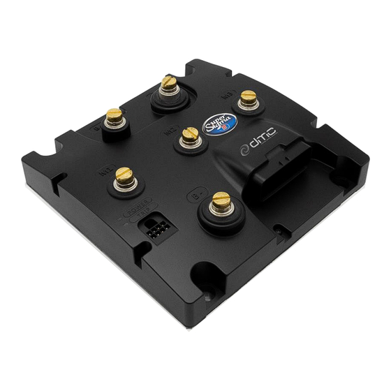
Page 12: Controller Wiring And Installation
This section will take care of describing the controller installation and connections. The picture below should be taken as reference for the naming of the available terminals and connectors present on any DMC Simga2NControllers. Simga2N Traction Advanced Manual– V1.3 Page 12 (166) ©2021 DMC GmbH Herten Germany... -
Page 13: Light Wiring
In this section the functions and features associated to each pin of the AMPSEAL 35-way connector, used for the controller light wiring will be described in details. Simga2N Traction Advanced Manual– V1.3 Page 13 (166) ©2021 DMC GmbH Herten Germany... -
Page 14: Light Wiring
3.1.1 Light wiring Connector A - Vehicle Interface - 35 Way (AMP SEAL Series) INTERNAL CIRCUITS: Simga2N Traction Advanced Manual– V1.3 Page 14 (166) ©2021 DMC GmbH Herten Germany... - Page 15 If the switch is opened while driving, no torque will be applied to the motor, which is left free to rotate, and Line Contactor will be opened. See [1] for further details about this function. Simga2N Traction Advanced Manual– V1.3 Page 15 (166) ©2021 DMC GmbH Herten Germany...
- Page 16 Pin A8 Analogue supply 5V – 10 mA max. A supply for 1-10kΩ Potentiometers is available to this pin with max 10mA capability for sourcing current. DMC recommends using a 5kΩ Potentiometer for best wire-off detection. Simga2N Traction Advanced Manual– V1.3 Page 16 (166) ©2021 DMC GmbH Herten Germany...
- Page 17 “M1.8-2 Steer pot middle point voltage level ”StrMid”” corresponds to a 0° steering angle, i.e. the vehicle no steering • “M1.8-3 Steer pot maximum voltage level ”StrMax””. defines the voltage corresponding to the minimum steering angle (full right hand lock) Simga2N Traction Advanced Manual– V1.3 Page 17 (166) ©2021 DMC GmbH Herten Germany...
- Page 18 In isolated-CAN version of the Simga2NController, when supplying the CAN bus with external 24V, pay attention to DMC Calibrator model before connect it. DMC Calibrators later than serial number D20340439 and without RS232 and Switch on the back can be supplied with more than 12V.
- Page 19 This pin has to be connected to Cosine output of analog sine cosine sensor if SineCos sensor technology is selected in “Menu 4 “Autotuning”. This pin is used in PMS/IPM motor application. Simga2N Traction Advanced Manual– V1.3 Page 19 (166) ©2021 DMC GmbH Herten Germany...
- Page 20 This pin has to be connected to the cathode (black lined side) of KTY84-130 thermistor or Pt 1000 ohm 0°C thermal sensor. The motor thermal sensor type can be selected by parameter “M5.2-1 Motor temperature sensor type “MtempTyp””. Simga2N Traction Advanced Manual– V1.3 Page 20 (166) ©2021 DMC GmbH Herten Germany...
- Page 21 +12V – This Pin holds a +12V supply for powering external devices. The maximum output current is limited to Pin B8 This Pin is tight to battery ground. Simga2N Traction Advanced Manual– V1.3 Page 21 (166) ©2021 DMC GmbH Herten Germany...
-
Page 22: Wiring Of Digital Inputs
3.1.2 Wiring of digital inputs The DMC Sigma2 controllers have the ability to set all digital inputs at runtime as active low or as active high. This setting is made in the controller setup menu. NOTICE! It is not possible to mix active low and active high inputs. - Page 23 With some controllers it is possible to activate the common input (Din 0) using a diode from the other inputs. With the DMC Sigma2 controller this is not possible. Use a double double-throw switch instead, as displayed in the schematic below. Both inputs are activated correctly.
- Page 24 Active High digital inputs For using Active High digital input The DMC Sigma2 controller must be setup for active high digital inputs by setting the parameter “M2-8Digital inputs active low/high ”ActvL/H”” to 1. Using a mechanical switch An active high digital input can be activated using a simple mechanical switch. The switch is wired between the B+ or Vbatt terminal and one of the digital inputs.
-
Page 25: Wiring Of Analog Inputs
The “Pin A8 Analogue supply 5V” has maximum current capability of 10mA. The “Pin A19 Supply 12V -- 70mA max.” has a maximum current capability of 70mA. Simga2N Traction Advanced Manual– V1.3 Page 25 (166) ©2021 DMC GmbH Herten Germany... - Page 26 In this case the analog/digital potentiometer has wire-off detection capability at “Pin A8 Analogue supply 5V”. The wire- off detection can be enabled by setting parameter “M2-6 Accelerator supply wire off detection ”SplyWrOf”” to 2. Simga2N Traction Advanced Manual– V1.3 Page 26 (166) ©2021 DMC GmbH Herten Germany...
- Page 27 2. Wire the second potentiometer (analog/electronic) between “Pin A8 Analogue supply 5V” and the negative power terminal of the battery; 3. Set “M2-6 Accelerator supply wire off detection ”SplyWrOf”” to 3. Simga2N Traction Advanced Manual– V1.3 Page 27 (166) ©2021 DMC GmbH Herten Germany...
- Page 28 If the voltage exceeds this range, wireoff is detected and F28 S004 happens. For more information about the wig-wag type potentiometer refer to “M1.6-2 Accelerator type ”AccelTyp””. Simga2N Traction Advanced Manual– V1.3 Page 28 (166) ©2021 DMC GmbH Herten Germany...
-
Page 29: Wiring Of The Can Bus
Non-isolated CAN bus wiring example without DMC Display: The schematic below shows how the CAN bus termination should be wired when no DMC Display is part of the CAN bus installation and the CAN lines are not isolated. The schematic also shows the optional wiring of a 8-way female Molex Minifit connector which could be used to plug the DMC Calibrator. - Page 30 Isolated CAN bus wiring example without DMC Display: The schematic below shows how the CAN bus termination should be wired when no DMC Display is part of the CAN bus installation and the CAN lines are isolated. The schematic also shows the optional wiring of a 8-way female Molex Minifit connector which could be used to plug the DMC Calibrator.
-
Page 31: Light Wiring Example For An Ac Traction Motor
3.1.5 Light wiring example for an AC traction motor NOTICE! The reported wiring example is referred to active low inputs Simga2N Traction Advanced Manual– V1.3 Page 31 (166) ©2021 DMC GmbH Herten Germany... -
Page 32: Light Wiring Example For An Ipm/Pms Traction Motor
3.1.6 Light wiring example for an IPM/PMS traction motor NOTICE! The reported wiring example is referred to active low inputs Simga2N Traction Advanced Manual– V1.3 Page 32 (166) ©2021 DMC GmbH Herten Germany... -
Page 33: Power Wiring
Always use a line contactor, controlled by the DMC controller, to enable the controller to switch off in unsafe situations. When an emergency battery disconnect switch is fitted, the key switch must be fed through an auxiliary switch to prevent over voltage damage due to disconnect during regen. -
Page 34: Power Wiring Examples
B+ terminal). Wiring example with external line contactor management ! Notice: the above scheme has to be followed strictly. Any variation must be agreed with DMC engineering first. Simga2N Traction Advanced Manual– V1.3 Page 34 (166) ©2021 DMC GmbH Herten Germany... - Page 35 Please notice that the DC/DC converter supplying the Sigma2N key line must be at least capable of outputting 5W for supplying the control logic. In case the application needs the DMC Sifgma2N Controller to drive one or more Digital Outputs, the user should consider upsizing the overmentioned DC/DC converter taking into account 2A for each driven output.
-
Page 36: Mechanical Installation
3.3 Mechanical installation The DMC Simga2NController family’s mechanical dimensions are reported in the figure above. Ever through all the controllers meet the IP65 protection against dust and water, it is suggested to choose carefully the installation location to protect them from damage. -
Page 37: Use Of Can Open Calibrator And Dmc Configurator
When connecting the DMC CAN Open Calibrator into a CAN network, it will communicate at a selectable baud rate. By default the DMC Calibrator is set to use 250 kbit/s baud rate. In case the baud rate of DMC CAN Open Calibrator and DMC Simga2N Controllers are not consistent, they will not communicate. -
Page 38: Dmc Configurator
Adjustments and DMC Calibrator’s map The DMC Calibrator is easy to use. The “up” and “down” buttons are used for scrolling lists up and down. Selections can be made with the “SEL” button. The “plus” and “minus” buttons are used to increase or decrease the parameter’s values. -
Page 39: Configurable Parameters
Menu 8.1 “DO1 - Line contactor” Menu 8 “Drivers setup” Menu 8.2 “DO2&3” Menu 8.3 “DO4” Menu 9.1 “Dual motor with steerpot” Menu 9 “Dual motor” Menu 9.2 “Dual motor without steerpot” Simga2N Traction Advanced Manual– V1.3 Page 39 (166) ©2021 DMC GmbH Herten Germany... -
Page 40: Menu 1 "Adjustment" For Traction Software
Menu 1.11 “Inching” • Menu 1.12 “Walkie” • Menu 1.13 “Speed fine tuning” • Menu 1.14 “Advanced drive modes” • Menu 1.15 “Generator menu” • Menu 1.16 “Vehicle menu” Simga2N Traction Advanced Manual– V1.3 Page 40 (166) ©2021 DMC GmbH Herten Germany... -
Page 41: Menu 1.1 "Drive Response
In speed mode Increasing the value results in a slower vehicle deceleration, while decreasing the value results in a faster vehicle deceleration. Simga2N Traction Advanced Manual– V1.3 Page 41 (166) ©2021 DMC GmbH Herten Germany... - Page 42 “M1.1-6 Direction brake torque “DBrake””. Between minimum and maximum, the braking strength is a value between the neutral and direction braking settings, proportional to the Accelerator potentiometer position. Speed Control Simga2N Traction Advanced Manual– V1.3 Page 42 (166) ©2021 DMC GmbH Herten Germany...
- Page 43 “M1.1-4 Neutral brake ramp time “NBrkRamp””. When the speed drops below “MxDbrSp” it is possible to select the reverse direction regardless of the accelerator position. Simga2N Traction Advanced Manual– V1.3 Page 43 (166) ©2021 DMC GmbH Herten Germany...
- Page 44 For example if with accelerator fully released the volt value at line 10 of test menu “Accel Pot [V]” is 0,3V set 51 “AccMin” to 0,5V for a proper behavior of the function Inhibit the change of direction”. Simga2N Traction Advanced Manual– V1.3 Page 44 (166) ©2021 DMC GmbH Herten Germany...
- Page 45 0% (depending on “M2-13 Variable/Constant ramp time “CnRmpTm””), when a “Halt” operation is commanded by the DS402 profile. For details please refer to [1]. Increasing the value gives a smoother but longer transition to zero speed. Simga2N Traction Advanced Manual– V1.3 Page 45 (166) ©2021 DMC GmbH Herten Germany...
- Page 46 0% (depending on “M2-13 Variable/Constant ramp time “CnRmpTm””), when a “Quick Stop” operation is commanded by the DS402 profile. For details please refer to [1]. Increasing the value gives a smoother but longer transition to zero speed. Simga2N Traction Advanced Manual– V1.3 Page 46 (166) ©2021 DMC GmbH Herten Germany...
-
Page 47: Menu 1.2 "End Of Braking
This parameter is only active when “M2-1 Control Mode “Spd/Torq”” is set to 3. It defines the ramp time to go from “M1.2-1 Speed threshold to enter End-of-Braking (EoB) mode ”SpdThEoB””. to zero speed when the footbrake is 100% pressed. Simga2N Traction Advanced Manual– V1.3 Page 47 (166) ©2021 DMC GmbH Herten Germany... - Page 48 During the end of braking operation, If pedal brake is removed and a direction selected with accelerator pedal demand (add foot switch in case of ride vehicle) the vehicle will start to move in the selected direction. Simga2N Traction Advanced Manual– V1.3 Page 48 (166) ©2021 DMC GmbH Herten Germany...
- Page 49 During the end of braking operation, If pedal brake is removed and a direction selected with accelerator pedal demand (add foot switch in case of ride vehicle) the vehicle will start to move in the selected direction. Simga2N Traction Advanced Manual– V1.3 Page 49 (166) ©2021 DMC GmbH Herten Germany...
- Page 50 During the end of braking operation, If pedal brake is removed and a direction selected with accelerator pedal demand (add foot switch in case of ride vehicle) the vehicle will start to move in the selected direction. Simga2N Traction Advanced Manual– V1.3 Page 50 (166) ©2021 DMC GmbH Herten Germany...
- Page 51 During the end of braking operation, If pedal brake is removed and a direction selected with accelerator pedal demand (add foot switch in case of ride vehicle) the vehicle will start to move in the selected direction. Simga2N Traction Advanced Manual– V1.3 Page 51 (166) ©2021 DMC GmbH Herten Germany...
- Page 52 In other words the hill hold time is ignored and the “M1.2-3 Neutral brake-end delay “NBrkEnd”” time is used. After that time the vehicle will roll on the slope at the restraint hill hold speed. Simga2N Traction Advanced Manual– V1.3 Page 52 (166) ©2021 DMC GmbH Herten Germany...
- Page 53 4) and 6) of the above list use a different time. In other words the hill hold time is ignored and the “M1.2-3 Neutral brake- Simga2N Traction Advanced Manual– V1.3 Page 53 (166) ©2021 DMC GmbH Herten Germany...
- Page 54 If digital input 7 is select as speed input 3 it never stops giving power to the motor even if this is activated. Simga2N Traction Advanced Manual– V1.3 Page 54 (166) ©2021 DMC GmbH Herten Germany...
- Page 55 Stop giving power to the motor and applying zero current on level ground if ““M3-4T Hill hold ”Off/HH/S””= 2 (Hill Hold & Stop giving power to the motor) Simga2N Traction Advanced Manual– V1.3 Page 55 (166) ©2021 DMC GmbH Herten Germany...
-
Page 56: Menu 1.3 "Creep
In Speed Control mode this sets the time taken to ramp up the speed form 0% to 100% or from 0% to the creep speed (depending on “M2-13 Variable/Constant ramp time “CnRmpTm””), when creep speed has to be applied. Simga2N Traction Advanced Manual– V1.3 Page 56 (166) ©2021 DMC GmbH Herten Germany... -
Page 57: Menu 1.4 "Speed Regulator
(“”). If the actual speed is higher than “Double PI speed threshold” the high speed gains are adopted (“Proportional gain speed controller” and “Integral gain speed controller”). Simga2N Traction Advanced Manual– V1.3 Page 57 (166) ©2021 DMC GmbH Herten Germany... - Page 58 In speed mode the M1.4- 8 Speed limit tolerance “SpLimTol” is acting on the Drive torque limit as indicate in the following figure. Simga2N Traction Advanced Manual– V1.3 Page 58 (166) ©2021 DMC GmbH Herten Germany...
- Page 59 To have a good drive feeling it is suggested to set this parameter between 0.2s and 0.05s. Too large values make the speed limitation unstable and provoking overshoots. Too small values make speed limitation fast but more aggressive. Simga2N Traction Advanced Manual– V1.3 Page 59 (166) ©2021 DMC GmbH Herten Germany...
-
Page 60: Menu 1.5 "Hill Hold
” is set to 1 or 2. It defines the speed that the vehicle should adopt after the hill hold time has elapsed and the restraint hill hold mode is entered. Simga2N Traction Advanced Manual– V1.3 Page 60 (166) ©2021 DMC GmbH Herten Germany... - Page 61 Suggested value: from 2.0 to 6.0 ”PosDBand” It defines a position feedback deadband around the setpoint, to help avoid instability caused by gear backlash. Suggested value: 0. Increase only if necessary. Simga2N Traction Advanced Manual– V1.3 Page 61 (166) ©2021 DMC GmbH Herten Germany...
-
Page 62: Menu 1.6 "Accelerator
“M1.6-5 Accelerator pot maximum voltage level “AccMax”” has to be lower than 4.5V. Both have to correspond to the actual wig wag potentiometer accelerator range. The wig-wag behavior is represented in the following image: Simga2N Traction Advanced Manual– V1.3 Page 62 (166) ©2021 DMC GmbH Herten Germany... - Page 63 Ramp”” and “M1.1-2 Accelerator release ramp time “Rel Ramp”” in torque mode. The behaviour of this parameter is explained by the following figure for Speed mode : Simga2N Traction Advanced Manual– V1.3 Page 63 (166) ©2021 DMC GmbH Herten Germany...
- Page 64 This adjustment is tuning the range of accelerator pedal that is used for braking and the threshold where the accelerator starts to demand driving torque. The following graph helps to understand the parameter behaviour. Simga2N Traction Advanced Manual– V1.3 Page 64 (166) ©2021 DMC GmbH Herten Germany...
- Page 65 This value sets the voltage on “Pin A9 Analogue AD1 i/p Accelerator -- Potentiometer” on 35-way connector from which reverse drive commences. Together with “M1.6-7 Wig/Wag forward threshold ”FwdTH””, this parameter forms a ‘dead band’ in which the wig-wag assumes a neutral position. Simga2N Traction Advanced Manual– V1.3 Page 65 (166) ©2021 DMC GmbH Herten Germany...
-
Page 66: Menu 1.7 "Brake Pedal/Ai2
2 or 3), this sets the voltage on the analogue input 2 that will correspond to 0 rpm speed limit. For tuning this parameter refer to “APPENDIX C – Analogue Input tuning”. Simga2N Traction Advanced Manual– V1.3 Page 66 (166) ©2021 DMC GmbH Herten Germany... - Page 67 ”Maximum motor frequency” (adjustable in “Menu 3 “Autotuning””) or to the maximum speed limit active. For tuning this parameter refer to “APPENDIX C – Analogue Input tuning”. Simga2N Traction Advanced Manual– V1.3 Page 67 (166) ©2021 DMC GmbH Herten Germany...
-
Page 68: Menu 1.8 "Steer Pot/Ai3
2 or 3), this sets the voltage on the analogue input 3 that will correspond to 0 rpm speed limit. For tuning this parameter refer to “APPENDIX C – Analogue Input tuning”. Simga2N Traction Advanced Manual– V1.3 Page 68 (166) ©2021 DMC GmbH Herten Germany... - Page 69 ”Maximum motor frequency” (adjustable in “Menu 3 “Autotuning””) or to the maximum speed limit active. For tuning this parameter refer to “APPENDIX C – Analogue Input tuning”. Simga2N Traction Advanced Manual– V1.3 Page 69 (166) ©2021 DMC GmbH Herten Germany...
-
Page 70: Menu 1.9 "Em Brake
The Following picture show a situation when the “M1-54 Electric brake delay “EBrkDly”” is set shorter than the time the vehicle takes to slow down below the “M1-18 Zero Speed Threshold to enter hill hold or neutral brake end ”ZSpdTh””. Simga2N Traction Advanced Manual– V1.3 Page 70 (166) ©2021 DMC GmbH Herten Germany... - Page 71 M1.9-2Electric brake release delay “EBRelDly”. If smooth starting on flat ground is wanted M1.9-3 Electric brake lock delay “ELkRdly” has to be set higher than M1.9-2 Electric brake release delay “EBRelDly”. Simga2N Traction Advanced Manual– V1.3 Page 71 (166) ©2021 DMC GmbH Herten Germany...
-
Page 72: Menu 1.10 "Powersteer
The trigger source is set by the parameter “M1.10-1 Power steer trigger ”PsF/FR/S”” in the Controller Set-up menu. Simga2N Traction Advanced Manual– V1.3 Page 72 (166) ©2021 DMC GmbH Herten Germany... -
Page 73: Menu 1.11 "Inching
“M2-13 Variable/Constant ramp time “CnRmpTm””) has to be applied. The maximum speed demand is set by ”Maximum motor frequency” (adjustable in “Menu 3 “Autotuning””), and it is assumed correspond to 100% of speed. Simga2N Traction Advanced Manual– V1.3 Page 73 (166) ©2021 DMC GmbH Herten Germany... -
Page 74: Menu 1.12 "Walkie
Notice that if any of these two parameters is set to 0 (or if both are set to 0), the Emergency Drive Forward will not be performed and the vehicle only performs the Emergency stop. Simga2N Traction Advanced Manual– V1.3 Page 74 (166) ©2021 DMC GmbH Herten Germany... - Page 75 Notice also that the fault related to Belly Switch button will only be displayed after the “Belly Switch time “BellyTim”” is elapsed. Simga2N Traction Advanced Manual– V1.3 Page 75 (166) ©2021 DMC GmbH Herten Germany...
-
Page 76: Menu 1.13 "Speed Fine Tuning
Increasing the value will smooth the activation of holding torque, but if set too long it will cause more roll back. The suggested value is between 0.5s and 2s. Simga2N Traction Advanced Manual– V1.3 Page 76 (166) ©2021 DMC GmbH Herten Germany... - Page 77 “M3-14 AccDamp” and “M3-15 LsAcDamp” combined effect (speed mode only) Simga2N Traction Advanced Manual– V1.3 Page 77 (166) ©2021 DMC GmbH Herten Germany...
- Page 78 For full release of accelerator pedal the neutral brake behaviour take over. The behavior of this parameter is explained by the following figure. ”M1.13-5 LsDcDamp” effect (speed mode only) This damping affects only the in speed mode. Simga2N Traction Advanced Manual– V1.3 Page 78 (166) ©2021 DMC GmbH Herten Germany...
- Page 79 20%) and releasing the accelerator pedal completely. Adjust slightly (suggested values are between 1.2 and 3) until brake feeling and stop time is fine. 3. Also try the feeling at medium speeds (40%, 50% and 60%). Simga2N Traction Advanced Manual– V1.3 Page 79 (166) ©2021 DMC GmbH Herten Germany...
-
Page 80: Menu 1.14 "Advanced Drive Modes
Foot brake ramp time adv mode 2 “FBrkRmp2” These settings are active when Advanced drive mode is selected from controller setup “M2-3Digital input 5 and 6 configuration ”Sp/In/Ad””. Simga2N Traction Advanced Manual– V1.3 Page 80 (166) ©2021 DMC GmbH Herten Germany... - Page 81 5 and 6 are configured to select Drive Style 2 (refer to Control set up “M2-3Digital input 5 and 6 configuration ”Sp/In/Ad”” for configuration details). Simga2N Traction Advanced Manual– V1.3 Page 81 (166) ©2021 DMC GmbH Herten Germany...
-
Page 82: Menu 1.15 "Generator Menu
In case the user is sending a regenerative BCL to the controller, the value of the Analogue input 3 will be used to rescale the said value. If any brake torque limitation becomes active in the controller, the regenerative power will be automatically cut to the said level. Simga2N Traction Advanced Manual– V1.3 Page 82 (166) ©2021 DMC GmbH Herten Germany... -
Page 83: Menu 1.16 "Vehicle Menu
For example if the actual motor speed is 3000 RPM and ”SpdRatio” is set to 100, the Vehicle Speed value that can be seen in the status menu or in the DMC display is 30.0 Kph (or 30.0 Mph). M1.16-2 Vehicle maximum speed ”VmaxSpd”... -
Page 84: Menu 2 "Controller Setup" For Traction Software
Menu 2 “Controller Setup” for traction software This menu embraces all the settings that are used to activate the DMC Simga2NController functions. It of extreme importance to set up this menu according to the desired functions required and then re-cycle the key to make changes active. - Page 85 Inputs 5 and 6 will operate as normally closed switches input. For the three different drive styles the following set of parameters are adopted: Normal Drive Style (input 5 closed & input 6 closed): Simga2N Traction Advanced Manual– V1.3 Page 85 (166) ©2021 DMC GmbH Herten Germany...
- Page 86 “MxDrTrq3””, respectively. The limits will be applied when the switch connected to pin 7 of 35-Way Connector is closed. When the switch is closed, the Sigmagauge and DMC Display will show a ‘parked’ icon. Simga2N Traction Advanced Manual– V1.3 Page 86 (166) ©2021 DMC GmbH Herten Germany...
- Page 87 If set from 0.5 to 10 [minutes] the stand-by timer is considered and active. M2-8 Digital inputs active low/high ”ActvL/H” This sets whether the digital inputs are active low or active high. Simga2N Traction Advanced Manual– V1.3 Page 87 (166) ©2021 DMC GmbH Herten Germany...
- Page 88 (parameter set to 1) on Walkie-type vehicles with speed control mode. This could lead to serious safety problems and cause operator’s injuries. DMC declines any responsibility for incorrect setup of this parameter. M2-10 Analog Input 3 configuration “AI3Cfg” This sets the function of potentiometer connected to the “Pin A12 Analogue AD3 -- Steer pot”.
- Page 89 (parameter set to 1) on Walkie-type vehicles with speed control mode. This could lead to serious safety problems and cause operator’s injuries. DMC declines any responsibility for incorrect setup of this parameter. M2-11 Digital output PWM chopping frequency “DO freq”...
- Page 90 If this parameter is set to 1 (load defaults) all the setting in all menus will be restored to the default factory values. This parameter requires a key cycle off-on to be effective. Simga2N Traction Advanced Manual– V1.3 Page 90 (166) ©2021 DMC GmbH Herten Germany...
-
Page 91: Menu 3 "Autotuning
Menu 3 “Autotuning” The DMC Simga2NController embeds the possibility to perform an automatic tuning of the motor’s sensor and parameters. Several feedback sensors can used and auto-tuned: Sin/Cos Encoder, Incremental encoder, Hall sensors and Resolvers. This feature allows the user to have plug-and-play configuration that ease the usage of the controller. A small set of data have to be entered for the procedure to be completed. -
Page 92: Menu 4 "Motor Setup
([4] for AC, [5] for PMS and [6] for IPM). Simga2N Traction Advanced Manual– V1.3 Page 92 (166) ©2021 DMC GmbH Herten Germany... -
Page 93: Menu 5 "Limits Setup
• Menu 5.6 “Timed current limit” • Menu 5.7 “I2t” • Menu 5.8 “Stall protection” • Menu 5.9 “Speed guard function” • Menu 5.10 “Encoder noise detection” Simga2N Traction Advanced Manual– V1.3 Page 93 (166) ©2021 DMC GmbH Herten Germany... -
Page 94: Menu 5.1 "Speed Limits
If set to 3 (Speed Limit and footbrake switch), then “Speed 1” sets the maximum speed of the vehicle when the switch connected to input 5 on 35way connector is open Simga2N Traction Advanced Manual– V1.3 Page 94 (166) ©2021 DMC GmbH Herten Germany... - Page 95 The speed limit ramp time is applied only if the actual motor speed is higher than speed limit one. Speed limit ramping is not applied when speed limit is removed. Simga2N Traction Advanced Manual– V1.3 Page 95 (166) ©2021 DMC GmbH Herten Germany...
- Page 96 Please notice that this parameter only acts on the speed limit set by the steerpot, all other limits will still use standard deceleration ramp time Simga2N Traction Advanced Manual– V1.3 Page 96 (166) ©2021 DMC GmbH Herten Germany...
-
Page 97: Menu 5.2 "Motor Thermal Limits
“TempStrt”” and is cut back proportionally to the temperature between the starting point and an adjustable span above it, selectable by means of “M5.2-3 Motor temperature cutback span “TempSpan””. Simga2N Traction Advanced Manual– V1.3 Page 97 (166) ©2021 DMC GmbH Herten Germany... - Page 98 This parameter is used to set an offset for the motor temperature measured by the sensor connected. It is useful to compensate sensor accuracy tolerance. It can be both positive and negative. Simga2N Traction Advanced Manual– V1.3 Page 98 (166) ©2021 DMC GmbH Herten Germany...
- Page 99 Please notice that it is only possible to enter only either ALL increasing resistance values (for classical thermal sensors) or ALL decreasing resistance values (for NTC thermal sensors). Simga2N Traction Advanced Manual– V1.3 Page 99 (166) ©2021 DMC GmbH Herten Germany...
-
Page 100: Menu 5.3 "Voltage Limits
The maximum drive power limit will run from 100 % (no cut back) to 0 % (full cut back). This is displayed also in the Status Menu at “DriveTqLim”. The low voltage start and end cut back levels are adjustable in the Sigma2 controllers. Simga2N Traction Advanced Manual– V1.3 Page 100 (166) ©2021 DMC GmbH Herten Germany... - Page 101 The maximum brake power limit will run from 100 % (no cut back) to 0 % (full cut back). This is displayed also in the Status Menu at “BrakeTqLim”. Simga2N Traction Advanced Manual– V1.3 Page 101 (166) ©2021 DMC GmbH Herten Germany...
- Page 102 However, when the user changes the direction from, say forward to reverse, the vehicle must first come to a stop before the actual direction can be changed. The controller will then use ‘direction braking’. Simga2N Traction Advanced Manual– V1.3 Page 102 (166) ©2021 DMC GmbH Herten Germany...
- Page 103 This is also a form of braking and here the high voltage cut back applies as well. Simga2N Traction Advanced Manual– V1.3 Page 103 (166) ©2021 DMC GmbH Herten Germany...
-
Page 104: Menu 5.4 "Battery Current Limits
This could lead to serious safety problems and cause operator’s injuries. DMC declines any responsibility for incorrect setup of this parameters. M5.4-3 Drive battery current limit adv mode 1 “IBatMax1” M5.4-4 Regenerative battery current limit adv mode 1 “IBatReg1”... - Page 105 If the setting is set to 0 the priority is given to the driving safe operation for avoiding possible roll back on slope. NOTICE! This parameter has a straight effect on the behaviour of a DMC Controller when: • It is used in torque mode, controller Via CAN in Setpoint mode;...
- Page 106 (If lower) (if lower) ADV drive style 1 active BCL Via CAN enabled BCL Via CAN timed out ADV mode enabled ADV drive style 1 active Simga2N Traction Advanced Manual– V1.3 Page 106 (166) ©2021 DMC GmbH Herten Germany...
-
Page 107: Menu 5.5 "Performance Table
For example if Maximum motor frequency is 200 Hz and the desired three Performance table speeds are: Speed1 50Hz, Speed2 130 Hz and Speed3 185Hz set PTSpeed 1 to 25% (50x100%/200) Speed2 to 65% (130x100%/200) and Speed 3 to 92% (185*100%/200) Simga2N Traction Advanced Manual– V1.3 Page 107 (166) ©2021 DMC GmbH Herten Germany... - Page 108 100%. To disable the torque cutback due to Performance Table; set the maximum torque at speed 1,2 ,3 to 100 % (setting 5.5-4 to 5.5-6) Simga2N Traction Advanced Manual– V1.3 Page 108 (166) ©2021 DMC GmbH Herten Germany...
-
Page 109: Menu 5.6 "Timed Current Limit
This could lead to serious safety problems and cause operator’s injuries. DMC declines any responsibility for incorrect setup of this parameters. Timed current Limit The graph below shows the parameters that are involved in setting up the Timed Current Limit. This feature can be used to protect the vehicle’s motor(s) from overheating. -
Page 110: Menu 5.7 "I 2 T
This could lead to serious safety problems and cause operator’s injuries. DMC declines any responsibility for incorrect setup of this parameters. These settings are part of I t function (pronounce as “I-squared-t”), that is a current limiting feature: the maximum current is limited with time. - Page 111 When the motor is running continuously for an infinite time, the motor temperature will rise to a temperature of 155 °C and will stabilize there. See also the graph below. Simga2N Traction Advanced Manual– V1.3 Page 111 (166) ©2021 DMC GmbH Herten Germany...
- Page 112 The reason that percentages are used instead of real currents, is that all other limit features such as low voltage limit and controller temperature limit are also in percentages. Note that the maximum current is specified by “Maximum motor current” (adjustable in “Menu 3 “Autotuning””). Simga2N Traction Advanced Manual– V1.3 Page 112 (166) ©2021 DMC GmbH Herten Germany...
- Page 113 Example • Controller temperature limit 50 % • t feature 80 % • → 50 % Applicable limit • → Controller temperature (indicated by ‘CT’). Applicable module Simga2N Traction Advanced Manual– V1.3 Page 113 (166) ©2021 DMC GmbH Herten Germany...
-
Page 114: Menu 5.8 "Stall Protection
Setting to 100% the “M5.8-1 Torque threshold for stall protection “TrqTHLim”” the function is disabled. As default stall protection is disabled. Simga2N Traction Advanced Manual– V1.3 Page 114 (166) ©2021 DMC GmbH Herten Germany... -
Page 115: Menu 5.9 "Speed Guard Function
Therefore if, for example, the vehicle is trying to climb a slope but is has not enough torque to succeed, the speed error will be very large and the function will recognise the “stall” condition, closing the EMbrake and avoiding the vehicle to roll back. Simga2N Traction Advanced Manual– V1.3 Page 115 (166) ©2021 DMC GmbH Herten Germany... -
Page 116: Menu 5.10 "Encoder Noise Detection
(F28 S001). This happen for excessive noise on encode signal (sensor damaged or bad wiring). ! IMPORTANT The change of these settings is active if key cycle power off/on is performed Simga2N Traction Advanced Manual– V1.3 Page 116 (166) ©2021 DMC GmbH Herten Germany... -
Page 117: Menu 6 "Battery Setup
If set to 4 (HyperDriveInnovation BMS), the Sigma2N Controller will expect to communicate with a HyperDriveInnovation BMS system. • If set to 5 (Lionic BMS), the Sigma2N Controller will expect to communicate with a Lionic BMS system. • If set to 6 (BatteryLabs BMS), the Sigma2N Controller will expect to communicate with a BatteryLabs BMS system. - Page 118 M6-7 BDI reset level “BDIreset” This sets the voltage at which the BDI will reset to show a 100% charged battery on the Sigmagauge or the DMC Display. This setting only has an effect at power-up. The adjustable range is from 18V to controller absolute maximum voltage, that corresponds to 125% of the nominal operating voltage of the controller.
- Page 119 M6-9 BDI warning level ”BDIwarn” This sets the level of battery voltage at which the BDI warning icon on the Sigmagauge and DMC Display will start to flash. The value is set as a percentage, where 100% corresponds to parameter “M6-7 BDI reset level “BDIreset”” and 0% corresponds to parameter “M6-8 BDI empty level “BDIempty””.
-
Page 120: Menu 7 "Can Bus Setup
The following sub-menus are available: • Menu 7.1 “CAN general” • Menu 7.2 “PDO premap” • Menu 7.3 “Shared line contactor” • Menu 7.4 “Display” • Menu 7.5 “Safe Stop 1” Simga2N Traction Advanced Manual– V1.3 Page 120 (166) ©2021 DMC GmbH Herten Germany... -
Page 121: Menu 7.1 "Can General
In case “M7.2-1 PDO free type “FreeMapT”” is set to 0 or 1, this is the node-ID that will be used for constructing the identifier of each message that the DMC Sigma2N Controller will be able to send/receive. In case “M7.2-1 PDO free type “FreeMapT”” is set to 2 or 3, the user has the possibility to assign any node number to the message identifiers, but SDO communication. - Page 122 Open IDs. Huge attention must be adopted when mapping the Controller’s PDOs. M7.1-6 CAN communication powerup delay “PwrUpDly” This parameter sets a delay in starting any activity on the CAN bus. Until the delay is elapsed, the DMC Controller will not try to send and/or receive any message on the bus.
-
Page 123: Menu 7.2 "Pdo Premap
Event timer TxPDO4 “TxPDO4Rt” M7.2-9 Event timer RxPDO1 “RxPDO1TO” M7.2-10 Event timer RxPDO2 “RxPDO2TO” For details about those parameters, please refer to the specific CAN Open manual [1]. Simga2N Traction Advanced Manual– V1.3 Page 123 (166) ©2021 DMC GmbH Herten Germany... -
Page 124: Menu 7.3 "Shared Line Contactor
M7.3-2 Shared line contactor reference node “Ref Node” M7.3-3 Shared line contactor refresh rate “SHLCRate” For details about those parameters, please refer to the specific CAN Open manual [1]. Simga2N Traction Advanced Manual– V1.3 Page 124 (166) ©2021 DMC GmbH Herten Germany... -
Page 125: Menu 7.4 "Display
Master having the lowest node number between them. M7.4-2 Display status field ”DispInfo” This sets the type of information that will appear in the General Indication Field of the DMC Display or how the Controller should behave with respect to the iGauge. - Page 126 NOTICE! If more than one DMC Sigma2N Controller is in the CAN network, make sure only one of them has this parameter set between 1 and 6. This will be the DMC Sigma2N Controller sending the drive and BDI information to the Display (and therefore the Display Master).
-
Page 127: Menu 7.5 "Safe Stop 1
4 and pre-mapping mode OR any variable mapped in RxPDOs in free-mapping mode). For details about those parameters, please refer to the specific CAN Open manual [1]. Simga2N Traction Advanced Manual– V1.3 Page 127 (166) ©2021 DMC GmbH Herten Germany... -
Page 128: Menu 8 "Drivers Setup
The menu embeds the configuration for the available digital outputs. The following sub-menus are available: • Menu 8.1 “DO1 - Line contactor” • Menu 8.2 “DO2&3” • Menu 8.3 “DO4” Simga2N Traction Advanced Manual– V1.3 Page 128 (166) ©2021 DMC GmbH Herten Germany... -
Page 129: Menu 8.1 "Do1 - Line Contactor
If set to 0, Line Contactor function is assigned to digital output driver 1 (“Pin A15 Contactor 1 o/p (Line)” of 35 way connector). The Line contactor will be managed by DMC Controller; • If set to 1, No function will be assigned to digital output 1. Under this condition, the output is available to be driven Via CAN. -
Page 130: Menu 8.2 "Do2&3
This option is highly NOT suggested on vehicles not equipped with mechanical brake. This option is not compatible with speed mode control (“M2-1 Control Mode “Spd/Torq”” set to 0). Simga2N Traction Advanced Manual– V1.3 Page 130 (166) ©2021 DMC GmbH Herten Germany... - Page 131 Mind that Option #9, on the other side, is designed to allow rolling backward or forward and will close the EM brake only when the motor stayed at zero speed for a certain time. Simga2N Traction Advanced Manual– V1.3 Page 131 (166) ©2021 DMC GmbH Herten Germany...
- Page 132 Be aware that this setting has to be set higher or equal to “M8.2-8 Digital output 3 holding voltage ”Do3HoldV””. If not a failure F7 S335 will occur. Simga2N Traction Advanced Manual– V1.3 Page 132 (166) ©2021 DMC GmbH Herten Germany...
- Page 133 Nominal battery voltage = 48V, Parameter set to 48V, Actual battery voltage = 52V. The applied voltage is 52V. Nominal battery voltage = 48V, Parameter set to 47V, Actual battery voltage = 52V. The applied voltage is 47V. Simga2N Traction Advanced Manual– V1.3 Page 133 (166) ©2021 DMC GmbH Herten Germany...
-
Page 134: Menu 8.3 "Do4
Via CAN. The user is therefore free to map in a CAN message (see [1] for details) the command to autonomously switch on and off the output. Simga2N Traction Advanced Manual– V1.3 Page 134 (166) ©2021 DMC GmbH Herten Germany... -
Page 135: Menu 9 "Dual Motor
“M9.1-1 Dual motor cut out ”DMcut”” defines a dead-band around zero steering in which speed is not limited; • “M9.1-4 Dual motor angle 3 ”DMang3”” defines the angle at which the speed limitation will act at its maximum value; Simga2N Traction Advanced Manual– V1.3 Page 135 (166) ©2021 DMC GmbH Herten Germany... - Page 136 “M9.1-7 Dual motor speed 3 ”DMspd3”” defines, as a percentage over the maximum speed set by ”Maximum motor frequency” (adjustable in “Menu 3 “Autotuning””), the maximum the speed limit applied. Simga2N Traction Advanced Manual– V1.3 Page 136 (166) ©2021 DMC GmbH Herten Germany...
-
Page 137: Menu 9.2 "Dual Motor Without Steerpot
If this setting is set to 0 (Limit in slave does not limit master), the master is not influenced at all by limitations happening in slave controller. Simga2N Traction Advanced Manual– V1.3 Page 137 (166) ©2021 DMC GmbH Herten Germany... -
Page 138: Safety Related Functions
6 Safety related functions The Sigma2N motor controller has some safety related functions that can be enable to enhance the application safety. The following list resumes the main function related to safety. Speed Guard Function In applications where speed control is adopted together with EM brake and no mechanical brake is installed, the system is relying on speed control accuracy for stopping and holding the vehicle until the EM brake is locking it in position. -
Page 139: Monitoring
1 rpm To reset the max and min temperatures logged data, press the + and – button at the same time when the controller is in neutral. Simga2N Traction Advanced Manual– V1.3 Page 139 (166) ©2021 DMC GmbH Herten Germany... - Page 140 Dual motor fail speed limit Torque limit Via CAN Unknown speed limit Drive torque limit from other motor Brake torque limit from other motor Generator torque limit Simga2N Traction Advanced Manual– V1.3 Page 140 (166) ©2021 DMC GmbH Herten Germany...
- Page 141 Node state operational M0-7 DS402 status table BDI States Description STARTUP Startup Switch on disabled RTSO Ready to switch on Switched on Operation enabled Quick stop Fault reset Fault Simga2N Traction Advanced Manual– V1.3 Page 141 (166) ©2021 DMC GmbH Herten Germany...
-
Page 142: Menu 10 "Test" For Traction Software
Sensor Sine Voltage SensSine 0 mV 3300 mV Raw AD Sensor CosSine Voltage SensCosine 0 mV 3300 mV Raw AD Sin/Cos Angle SnCsAngle ° 0.0° 360.0 ° Simga2N Traction Advanced Manual– V1.3 Page 142 (166) ©2021 DMC GmbH Herten Germany... -
Page 143: Menu 12 "About
Product serial number SN P 12345678 Logic serial number SN L 87654321 Logic version and variant HWver V5.05-STD Product tested and calibrated HWcal Y Y HW LEM Simga2N Traction Advanced Manual– V1.3 Page 143 (166) ©2021 DMC GmbH Herten Germany... -
Page 144: Diagnostics
Walkie and Control Via CAN HMI both active Adjustment range Hill hold Enabled and Torque control enabled Can Node ID via digital input enabled but control but Control Via CAN HMI is not enabled. Simga2N Traction Advanced Manual– V1.3 Page 144 (166) ©2021 DMC GmbH Herten Germany... - Page 145 If the Master mode 3 is a Pump controller, make sure that also “M3-18 Failure option” and “M3-41 Speed limits instead of torque limits ” are set to 0. Simga2N Traction Advanced Manual– V1.3 Page 145 (166) ©2021 DMC GmbH Herten Germany...
- Page 146 (“M5.1-11 Speed limit as a cut “SpdLmCut””) Hill Hold setting not consistent between controller pairs. Make sure both controllers have the same setting (“M1.5-1 Hill hold enable ”Off/HH/S””) Simga2N Traction Advanced Manual– V1.3 Page 146 (166) ©2021 DMC GmbH Herten Germany...
- Page 147 RxPDO. Dual motor BMS activation not consistent between controller pairs Dual motor and Shared Line contactor ID message option (11/29 bit IDs) incompatible with PDO mapping. Simga2N Traction Advanced Manual– V1.3 Page 147 (166) ©2021 DMC GmbH Herten Germany...
- Page 148 Object index 0x3842 subindex 0x0 (Fault subcode extended), embeds this information in the format XXYYZZ, where XX is the menu number, YY is the >999 submenu number and ZZ is the item number. This is what the DMC calibrator shows. Object index 0x3841 subindex 0x0 (Fault subcode), embeds this information in the format XYYZZ (if X <=6) or XYZZ (if X >...
- Page 149 (e.g. short circuit) Digital contactor output 2 short circuit when closed Digital contactor output 3 short circuit during initialization Digital contactor output 3 short circuit at closing Simga2N Traction Advanced Manual– V1.3 Page 149 (166) ©2021 DMC GmbH Herten Germany...
- Page 150 Pump shutdown because of other motor limiting Motor high temperature shutdown sided mosfets M1 mosfets short circuit during M2 mosfets power up and before M3 mosfets line contactor is closed Simga2N Traction Advanced Manual– V1.3 Page 150 (166) ©2021 DMC GmbH Herten Germany...
- Page 151 > 0 See table "Motor sub error codes" inconsistency Could not initialize the calibration Current sensor calibration fault Time out during calibration Controller temperature over 100 degree Simga2N Traction Advanced Manual– V1.3 Page 151 (166) ©2021 DMC GmbH Herten Germany...
- Page 152 Time out on configuration upload Generic time out Time out on getting stable inputs Time out on motor ready System Fault Internal system error Contact DMC Simga2N Traction Advanced Manual– V1.3 Page 152 (166) ©2021 DMC GmbH Herten Germany...
-
Page 153: Ac Motor Sub Error Codes
Refer to DMC. internal error. Refer to DMC. Internal error load default and reparametrize by means of autotuning. If persist refer to DMC. internal error: load default and reparametrize by means of autotuning. If persist refer to DMC. -
Page 154: Pms Motor Error Subcodes
The motor module could not be initialized. Load Default Parameter and key cycle An motor overcurrent is detected. Check if motor tuned properly, check motor wiring (lack of isolation).. Internal error refer to DMC Wrong current setup: current for Autotuning is set greater than maximum current. Check current setup in tha autotuning menu. -
Page 155: Ipm Motor Error Subcodes
Description Code No errors in the motor module The motor module could not be initialized. Report to DMC An overcurrent is detected: Motor is overloaded or wrong position sensor settings Internal error Report to DMC Wrong current: rated motor current is greater than maximum: Check setting 8 and 7 in the autotune menu Wrong poles number. -
Page 156: Menu 11 "Fault Log
Holding the (+) button shows the fault sub error code. NOTICE! To reset the fault log data, press the + and – button at the same time when the controller is in neutral. Simga2N Traction Advanced Manual– V1.3 Page 156 (166) ©2021 DMC GmbH Herten Germany... -
Page 157: Software Updates
In case an update has to be performed on a DMC Simga2NController, a “DMC Flash Cable” is needed (part number 980/SS2). This cable acts as a USB interface dongle and has to be plugged into “Connector B - Communications - 8 Way”... -
Page 158: Dmc Displays
Developed as a the new generation for the DMC Display, the DMC Lite Display maintains the flexibility of its predecessor, introducing a brand new graphical design. The DMC Lite Display still operates on the CAN bus and has the capability of showing the information of up to 6 DMC Sigms2N Controllers at the same time. -
Page 159: Dmc Advanced Display
10.2 DMC Advanced Display Developed as a plug-in vehicle dashboard, the DMC Advanced Display represents the state-of-art of vehicle monitoring. It features a modern graphical design, combined with the capability of interacting with up to 8 nodes, further than with a BMS. -
Page 160: Dmc Igauge
It is capable of indicating lead acid battery discharge state, hours counter and the main SuperSigma2N fault messages. The iGause is communicating with a DMC SuperSigma2N Controller through the UART protocol. To this means, it must be wired as in the following picture and plugged into the “Connector B - Communications - 8 Way”... -
Page 161: Available Application Notes And Manuals
180618 Simga2NAN 180618 - CAN Open Compatible protocol V2.12 V2.12 200228 Simga2NAN 200228 - Dual motor functionalities V1.0 V1.0 190702 DMC Display AN 190702 – Colour Display V1.3 V1.3 Simga2NAC Manual V1.0 V1.0 Simga2NIPM Manual V1.0 V1.0 Simga2NPMS Manual V1.0 V1.0... -
Page 162: Appendix A - Technical Specifications
EN 61000-6-3 (2007) +A1 (2011) + AC (2005) (Residential Emissions, Class B) EN 61000-6-2 (2005) + AC (2005) (Industrial Immunity) The machine manufacturer is responsible for the compliance of the complete system with the appropriate regulations. Simga2N Traction Advanced Manual– V1.3 Page 162 (166) ©2021 DMC GmbH Herten Germany... - Page 163 Always use a torque wrench when fixing the power terminals. Exceeding the maximum specified torque can cause serious damage to the controller and warranty might be void. Too long bolts damage the controller. Simga2N Traction Advanced Manual– V1.3 Page 163 (166) ©2021 DMC GmbH Herten Germany...
-
Page 164: Appendix B - Emc Guidelines
A working balance needs to be established by experiment. The complete installation should be documented, in detail, and faithfully reproduced on all production vehicles. When making changes, consider their effect on compliance ahead of any consideration of cost reduction or other “improvement”. Simga2N Traction Advanced Manual– V1.3 Page 164 (166) ©2021 DMC GmbH Herten Germany... -
Page 165: Appendix C - Analogue Input Tuning
1). 10. Enter “Menu 1 “Adjustment” for traction software” and set parameter “M1.8-3 Steer pot maximum voltage level ”StrMax”” as the voltage level found at point 2). Simga2N Traction Advanced Manual– V1.3 Page 165 (166) ©2021 DMC GmbH Herten Germany... -
Page 166: Appendix D - Resolver
4,7 Vac peak Excitation frequency: 8 kHz Max supply current: 150 mA Sin cos feedback signal max range: ± 1,65 V AC Max resolver gain: 0,35 Wiring Simga2N Traction Advanced Manual– V1.3 Page 166 (166) ©2021 DMC GmbH Herten Germany...
Need help?
Do you have a question about the Sigma2N and is the answer not in the manual?
Questions and answers