Table of Contents
Advertisement
Quick Links
This user manual details the features of the complete Pro Controller range:
1.
Pro-AC range
2.
Pro-SEM range
3.
Pro-PM4 range
4.
Pro-Series range
5.
Pro-Pump range
6.
Pro-BPM range
Modification History:
Revision
Issue Date
1.04.00
27-08-2003
1.05.00
10-10-2003
1.06.00
30-01-2004
2.00.00
23-06-2004
2.01.00
15-07-2004
2.02.00
01-12-2004
2.03.00
04-02-2005
3.01.00
19-08-2005
© 2005 DMC GmbH Herten
Pro Controller Manual
24-120V, 125-650A
24-120V, 125-650A
24-120V, 125-650A
24-120V, 125-650A
24-120V, 125-650A
24-120V, 125-650A
Author
Changes
R.P.
Dual Motor proportional added
R.P.
Updates: Series traction & pump + general updates
R.P.
Several updates & fixes
R.P.
Support for the updated hardware and fixes + I-max increased
R.P.
Plugging setting added in motor setup PSR (series)
R.P.
Dual Pump Controller added & Improved regen adjustments (series)
R.P.
Safety improvements. SR field weakening & Speed indication.
R.P.
Modified CAN communications for display and calibrator & bugfixes
T.B.A.
Pro-Controller manual – Revision 3.01.00 09/2005
1
Advertisement
Table of Contents

Related Manuals for DMC PSE445TM01


Summary of Contents for DMC PSE445TM01
- Page 1 Dual Pump Controller added & Improved regen adjustments (series) 2.03.00 04-02-2005 R.P. Safety improvements. SR field weakening & Speed indication. 3.01.00 19-08-2005 R.P. Modified CAN communications for display and calibrator & bugfixes © 2005 DMC GmbH Herten Pro-Controller manual – Revision 3.01.00 09/2005...
-
Page 2: Table Of Contents
CONTENTS DMC PHILOSOPHY – INTRODUCTION ....................3 PRO CONTROLLER VARIANTS ........................ 4 CONTROLLER FEATURES......................... 5 TECHNICAL SPECIFICATIONS......................... 6 ............................... 6 LECTRICAL ............................6 NVIRONMENTAL ............................. 6 ECHANICAL CALIBRATOR AND ADJUSTMENTS ......................7 ............................7 ALIBRATOR ............................7 ALIBRATOR MAP : “1 A ”... -
Page 3: Dmc Philosophy - Introduction
DMC has invested in a purpose built state of the art production facility. The Company has been formed with enthusiasm and professionalism to create and develop a unique new product range in this particular "niche"... -
Page 4: Pro Controller Variants
177 x 155 x 38mm PPM425ES** 24-48V 250A PM Electric Power Steer (EPS) 177 x 155 x 38mm PPM817ES** 72-80V 175A PM Electric Power Steer (EPS) 177 x 155 x 38mm Pro-Controller Manual - revision 3.01.00 09/2005 © 2005 DMC GmbH Herten... -
Page 5: Controller Features
Number of Digital switch inputs. Number of Analogue inputs Number of Contactor drive outputs (3 Amps) Number of signal only (DMC external driver module needed) 24V - 96V Operation Single PCB design, no internal connections IMS PCB for superb thermal conduction... -
Page 6: Technical Specifications
Always use a torque wrench when fixing the power terminals. • Exceeding the maximum specified torque can cause serious damage to the controller and warranty might be void. • To long bolts damage the controller. Pro-Controller Manual - revision 3.01.00 09/2005 © 2005 DMC GmbH Herten... -
Page 7: Calibrator And Adjustments
3. To be able to update the software it is necessary to have a software package installed and off course a copy of the new DMC software release. For detailed information on updating software please contact your DMC supplier. -
Page 8: Traction Controller: "1 Adjustments
100 % 1.0 % 100 % • Depending on controller type and configuration some settings will be not available (N/A). • * Selectable multi function. • *² DM= Dual motor Pro-Controller Manual - revision 3.01.00 09/2005 © 2005 DMC GmbH Herten... -
Page 9: Pump Controller: "1 Adjustments
• The pump inhibit input does not disable power steer • Depending on controller type and configuration some settings will be not available (N/A). • * Selectable multi function. © 2005 DMC GmbH Herten Pro-Controller manual – Revision 3.01.00 09/2005... -
Page 10: Status Menu For All Controllers: "2 Status
20 M3 AC, SE, PM 0.5 V Digital (0/1) or analog values (0-125V) 21-24 Dbug Debug (DMC internal use only) Service and fault log reset press + and – together to reset service log (only possible when controller in neutral) Status... -
Page 11: Setup Menu For All Controllers: "3 Controller Setup
2=Main & Warning faults 0=None, 1=Acc, 2=Motor V/RPM, 3=Speed 11 Display Status field Of/D/V/K 0 – 4 in Kph, 4=Steering 0=None, 1= DMC , 2= ? 12 Display Name Initdisp 0 – 255 13 Motor temp. sensor typ MTempTyp 0 – 255... -
Page 12: Ac Controller: "4 Motor Setup
• * Reset to make changes active. Recycle the key switch (Also indicated on calibrator ‘key’) • Changes on parameter 5 up to 32 become active after selecting neutral Pro-Controller Manual - revision 3.01.00 09/2005 © 2005 DMC GmbH Herten... -
Page 13: Sem Controller: "4 Motor Setup
The fault log remembers the last occurred fault and stores the key hours when the fault happened. To reset the fault- and service log press the + and – button at the same time when the controller is in neutral. (See also the status menu) © 2005 DMC GmbH Herten Pro-Controller manual – Revision 3.01.00 09/2005... -
Page 14: Test Menu For All Controllers: "5 Test
2 Application App Standard 3 Motor type Motor SEM 4 Controller type Type PSE865TL01 5 Hardware Voltage and current HW 80V 650A 65A 6 Software version SW 3.01.00 190805 Pro-Controller Manual - revision 3.01.00 09/2005 © 2005 DMC GmbH Herten... -
Page 15: Diagnostics
F a u l t s (Recycle to neutral) 9 Eeprom can not be E-eprom not accessible Internal supply voltage below12 volt. Call DMC if this problem occurs accessed 10 2 Direction fault Both forward and reverse selected. Recycle Check direction switch and wiring. -
Page 16: Dashboard Display
General information Brand name window. When required DMC can fit the customers name and logo here during production. <1> <2> Membrane buttons. Used for setting functions as Service interval timer, Hours counter and the Customer information field <6>. -
Page 17: Installation
The contactor mounting plane can affect performance, contactors should never be mounted with their terminal studs vertically down. For further applications information on contactors, please consult DMC GmbH in Herten. The controller may be supplied as a stand-alone unit or pre-wired onto a base-plate with contactors etc. -
Page 18: 10 Emc Guidelines
A working balance needs to be established by experiment. The complete installation should be documented, in detail, and faithfully reproduced on all production vehicles. When making changes, consider their effect on compliance ahead of any consideration of cost reduction or other “improvement”. Pro-Controller Manual - revision 3.01.00 09/2005 © 2005 DMC GmbH Herten... -
Page 19: 11 Graphics
11 GRAPHICS Figure 1 Accelerator Characteristics Figure 2 Thermal Cutback Characteristic © 2005 DMC GmbH Herten Pro-Controller manual – Revision 3.01.00 09/2005... - Page 20 All inputs are Normally Open (NO). Only the speed inputs are Normally Closed (NC) • Driver 3 is not available on ´small´ controllers, use the DMC driver module instead. Pro-Controller Manual - revision 3.01.00 09/2005 © 2005 DMC GmbH Herten...
- Page 21 Power Wiring – AC Optional protection diode ~ AC Figure 5 Power Wiring – SEM Optional protection diode Field Figure 6 Power Wiring – PM4 Optional protection diode (Not connected) © 2005 DMC GmbH Herten Pro-Controller manual – Revision 3.01.00 09/2005...
- Page 22 Powersteer) When an emergency battery disconnect switch is fitted, the key switch must be fed through an auxiliary switch to prevent over voltage damage due to disconnect during regen. Pro-Controller Manual - revision 3.01.00 09/2005 © 2005 DMC GmbH Herten...
-
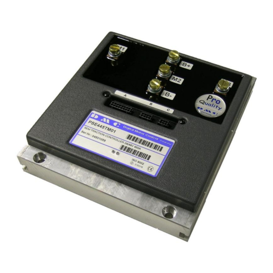
Page 23: 12 Mechanical Drawings
Overall height (incl. Terminals): 38mm Power terminals: M6 (5x) Fixings M6 (4x) Connector A: 16 way Molex Microfit 3.0 Connector B: 8 way Molex Microfit 3.0 Connector C: 6 way Molex Microfit 3.0 © 2005 DMC GmbH Herten Pro-Controller manual – Revision 3.01.00 09/2005...
Need help?
Do you have a question about the PSE445TM01 and is the answer not in the manual?
Questions and answers