
Subscribe to Our Youtube Channel
Related Manuals for HIKVISION DS-3WAP622G-SI


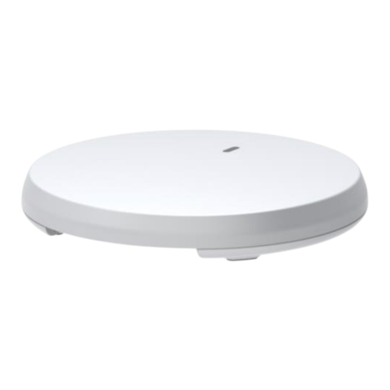
Summary of Contents for HIKVISION DS-3WAP622G-SI
- Page 1 Wireless Access Point Quick Start Guide Punto de Acceso Inalámbrico Guía de inicio rápido Ponto de acesso sem fio Guia de início rápido Wireless Access Point Panduan Mulai Cepat...
- Page 2 CONTENTS English Español Português Bahasa...
-
Page 3: Legal Information
Products described in this Document, which may include licenses obtained from third parties. Any part of the Document, including text, pictures, graphics, etc., belongs to Hikvision. No part of this Document may be excerpted, copied, translated, or modified in whole or in part by any means without written permission. - Page 4 English USE OF THE PRODUCT, EVEN IF HIKVISION HAS BEEN ADVISED OF THE POSSIBILITY OF SUCH DAMAGES OR LOSS. YOU ACKNOWLEDGE THAT THE NATURE OF THE INTERNET PROVIDES FOR INHERENT SECURITY RISKS, AND HIKVISION SHALL NOT TAKE ANY RESPONSIBILITIES FOR ABNORMAL OPERATION, PRIVACY LEAKAGE OR OTHER DAMAGES RESULTING FROM CYBER-ATTACK, HACKER ATTACK, VIRUS INFECTION, OR OTHER INTERNET SECURITY RISKS;...
-
Page 5: Applicable Models
English Applicable Models This manual is applicable to DS-3WAP series ceiling-mounting access points, including DS- 3WAP622G-SI, DS-3WAP622E-SI, and DS-3WAP522-SI models. Symbol Conventions The symbols that may be found in this document are defined as follows. Symbol Description Provides additional information to emphasize or supplement Note important points of the main text. -
Page 6: Chapter 1 Device Installation
English Chapter 1 Device Installation Note Never place the device in an unstable location. The device may fall, causing serious personal injury or death. Install safety protection equipment if necessary. Check regularly. It is recommended to install the device according to the following instructions. We are not responsible for any results coming from individual arbitrary modification or installation. - Page 7 English Table 1-2 Packing List Item Quantity Smart Managed Access Point × 1 Mounting Bracket × 1 Screw Pack × 1 Quick Start Guide × 1 Regulatory Compliance and Safety Information × 1...
- Page 8 English Table 1-3 Bracket Introduction Description Installation holes used to attach the mounting bracket to a wall or a ceiling tile. T-rail clip installation holes for T-rail mounting. Cable tie installation hole for securing device cables. 86 panel installation holes used to attach the mounting bracket to an 86 panel. The distance between the two holes is 60 mm (2.36 in).
- Page 9 English...
- Page 10 English Note Make sure the screw does not block the keyhole slot.
- Page 11 English Mounting Device on Ceiling Note The installation method of the M3 × 23.5 mm security screw is the same for wall mounting and ceiling mounting. and fasten washers and nuts at the other side of the ceiling to secure the mounting bracket to the ceiling.
- Page 12 English and slide down the device until it clicks into place. Note No cable tie is provided with the device. Prepare one yourself. 1. Insert a cable tie through the cable tie installation hole on the mounting bracket before connecting cables to the device. 2.
-
Page 13: Chapter 2 Cable Connection
English Chapter 2 Cable Connection Note No power adapter is provided with the device. Prepare one yourself. Table 2-1 Power Adapter Specifications Item Description Power Input 100~240 V AC Power Output 12 V/1.5 A Power Output Power ≥ 18 W To power the AP through PoE, use an Ethernet cable to connect an Ethernet port on a PoE switch to the PoE port on the AP. -
Page 14: Chapter 3 Led Status Description
English Chapter 3 LED Status Description Table 3-1 LED Status Description Status Description No power is present or the LED has been turned off from the CLI. The AP is initializing, or an initialization Steady on exception has occurred. Yellow Fast flashing All Ethernet ports are down. - Page 15 English Chapter 4 FAQ Scan the QR code below for more information.
-
Page 16: Información Legal
Por favor, encuentre la versión más reciente de este Documento en la página web de Hikvision (https://www.hikvision.com). A menos que se convenga lo contrario, Hangzhou Hikvision Digital Technology Co., Ltd. o sus filiales (en lo sucesivo, "Hikvision") no ofrecen garantí as, expresas o implí citas. - Page 17 DOCUMENTACIÓ N, YA SEA POR INCUMPLIMIENTO DE CONTRATO, AGRAVIO (INCLUIDA LA NEGLIGENCIA), RESPONSABILIDAD POR EL PRODUCTO O DE OTRO TIPO, EN RELACIÓ N CON EL USO DEL PRODUCTO, INCLUSO SI HIKVISION HA SIDO ADVERTIDO DE LA POSIBILIDAD DE TALES DAÑ OS O PÉRDIDAS.
-
Page 18: Instrucciones De Seguridad
Modelos aplicables Este manual es aplicable a puntos de acceso de la serie DS-3WAP que permiten montaje en techo, incluyendo los modelos DS-3WAP622G-SI, DS-3WAP622E-SI y DS-3WAP522-SI. Convenciones de sí mbolos A continuación se definen los sí mbolos que puede encontrar en este documento. -
Page 19: Capítulo 1 Instalación Del Dispositivo
Español Capítulo 1 Instalación del Dispositivo Nota Nunca coloque el dispositivo en un lugar inestable. El dispositivo podría caerse y provocar lesiones personales graves o la muerte. Instale equipos de protección de seguridad si es necesario. Revíselo periódicamente. Se recomienda instalar el dispositivo de acuerdo con las siguientes instrucciones. No somos responsables de ningún resultado proveniente de modificaciones o instalaciones arbitrarias individuales. - Page 20 Español Table 1-2 Lista de Contenido en el Empaque Elemento Cantidad Punto de Acceso con Gestión Inteligente × 1 Soporte de montaje × 1 Paquete de Tornillos × 1 Guí a de inicio rápido × 1 Cumplimiento de la Normativa e Información ×...
- Page 21 Español Tabla 1-3 Introducción del Soporte Descripción Orificios de instalación utilizados para fijar el soporte de montaje a una pared o a una placa de techo. Orificios de instalación de sujetador para riel en T para montaje en riel en T. Orificio de instalación de bridas para asegurar los cables del dispositivo.
- Page 22 Español...
- Page 23 Español Nota Asegúrese que el tornillo no bloquea la ranura de la cerradura.
- Page 24 Español Montaje de Dispositivo en el Techo Nota El método de instalación del tornillo de seguridad M3 de 23.5 mm es el mismo para el montaje en la pared y en el techo. y ajuste las arandelas y tuercas en el otro lado del techo para asegurar el soporte de montaje al techo.
- Page 25 Español deslice el dispositivo hacia abajo hasta que encaje en su sitio. Nota No se suministra ninguna brida para cables con el dispositivo. Obtenga una por su cuenta. 1. Inserte una brida para cables a través del orificio de instalación de la brida para cables en el soporte de montaje antes de conectar los cables al dispositivo.
-
Page 26: Capítulo 2 Conexión De Cables
Español Capítulo 2 Conexión de Cables Nota No se proporciona ningún adaptador de corriente con el dispositivo. Obtenga una por su cuenta. Tabla 2-1 Especificaciones del Adaptador de Corriente Elemento Descripción Entrada de alimentación 100 ~ 240 V CA Salida de Potencia 12 V / 1.5 A Potencia de Salida ≥... - Page 27 Español Capítulo 3 Descripción del Estado del LED Tabla 3-1 Descripción del Estado del LED Estado Descripción No hay energía o el LED se ha apagado Apagado desde la Interfaz de Línea de Comandos (CLI). El AP se está inicializando o se ha Encendido estable producido una excepción de inicialización.
-
Page 28: Capítulo 4 Preguntas Frecuentes
Español Capítulo 4 Preguntas Frecuentes Escanee este código QR para obtener más información. -
Page 29: Informação Legal
NA MEDIDA MÁXIMA PERMITIDA PELA LEI APLICÁVEL, ESTE DOCUMENTO E O PRODUTO DESCRITO, COM O SEU HARDWARE, SOFTWARE E FIRMWARE, SÃO FORNECIDOS “TAL COMO ESTÃO” E “COM TODAS AS SUAS FALHAS E ERROS”. A HIKVISION EXCLUI, DE FORMA EXPLÍCITA OU IMPLÍ CITA, INCLUINDO E SEM LIMITAÇÃO, GARANTIAS DE COMERCIABILIDADE, QUALIDADE DO SERVIÇO OU ADEQUAÇÃO A UMA FINALIDADE ESPECÍ... - Page 30 DO CONTRATO, ATOS ILÍ CITOS (INCLUINDO NEGLIGÊNCIA), RESPONSABILIDADE PELO PRODUTO OU, DE OUTRO MODO, RELACIONADA COM A UTILIZAÇÃO DO PRODUTO, AINDA QUE A HIKVISION TENHA SIDO AVISADA SOBRE A POSSIBILIDADE DE TAIS DANOS OU PERDAS. O USUÁRIO RECONHECE QUE A NATUREZA DA INTERNET OFERECE RISCOS DE SEGURANÇA INERENTES E QUE A HIKVISION NÃO SERÁ...
- Page 31 Modelos aplicáveis Este manual é aplicável à série de pontos de acesso de montagem no teto DS-3WAP, incluindo os modelos DS-3WAP622G-SI, DS-3WAP622E-SI e DS-3WAP522-SI. Convenções relativas aos sí mbolos Os sí mbolos presentes neste documento são definidos da seguinte maneira.
-
Page 32: Capítulo 1 Instalação Do Dispositivo
Português Capítulo 1 Instalação do dispositivo Nota Nunca coloque o dispositivo em um local instável. O dispositivo pode cair e causar sérios ferimentos ou morte. Instale equipamentos de proteção de segurança, se necessário. Verifique regularmente. Recomendamos instalar o dispositivo de acordo com as instruções a seguir. Não nos responsabilizamos por quaisquer resultados decorrentes de modificações ou instalações arbitrárias individuais. - Page 33 Português Nota A lista da embalagem varia de acordo com o dispositivo. A lista da embalagem real prevalece. Quaisquer outros acessórios de instalação necessários durante a instalação devem ser preparados por você. Tabela 1-2 Lista da embalagem Item Quantidade Ponto de acesso gerenciado com inteligência ×...
- Page 34 Português Tabela 1-3 Introdução do suporte N° Descrição Furos de instalação usados para fixar o suporte de montagem em uma parede ou placa de teto. Furos de instalação da presilha do trilho em T para montagem no trilho em T. Furo para instalação de braçadeiras para fixar os cabos do dispositivo.
- Page 35 Português Nota Um boa prática é conectar os cabos ao dispositivo antes de montá-lo. Instale o parafuso de segurança M3 × 23,5 mm conforme necessário. Dispositivo de montagem na parede...
- Page 36 Português Nota Certifique-se de que o parafuso não bloqueie a abertura da fechadura.
- Page 37 Português Montagem do dispositivo no teto Nota O método de instalação do parafuso de segurança M3 × 23,5 mm é o mesmo para montagem na parede e no teto.
- Page 38 Português e fixe arruelas e porcas no lado oposto do teto para fixar o suporte de montagem ao teto. e deslize o dispositivo para baixo até que ele se encaixe no lugar adequado. Nota Nenhuma braçadeira é fornecida com o dispositivo. Prepare uma você mesmo. 1.
- Page 39 Português...
- Page 40 Português Capítulo 2 Conexão de cabos Nota Nenhum adaptador de energia é fornecido com o dispositivo. Prepare uma você mesmo. Tabela 2-1 Especificações do adaptador de energia Item Descrição Entrada de energia 100~240 VCA Saí da de alimentação 12 V/1,5 A Potência de saí...
- Page 41 Português Capítulo 3 Descrição do status do LED Tabela 3-1 Descrição do status do LED Status Descrição Não há energia presente ou o LED foi Desligado desligado pela CLI. O ponto de acesso está sendo Acesa fixa inicializado ou ocorreu um erro de inicialização.
-
Page 42: Capítulo 4 Perguntas Frequentes
Português Capítulo 4 Perguntas Frequentes Escaneie o código QR abaixo para obter mais informações. - Page 43 Produk yang dijelaskan dalam Dokumen ini, yang mungkin termasuk lisensi yang diperoleh dari pihak ketiga. Setiap bagian dari Dokumen, termasuk teks, gambar, grafik, dll., adalah milik Hikvision. Tidak ada bagian dari Dokumen ini yang boleh dikutip, disalin, diterjemahkan, atau dimodifikasi secara keseluruhan atau sebagian dengan cara apa pun tanpa izin tertulis.
- Page 44 DIBERITAHUKAN MENGENAI KEMUNGKINAN KERUSAKAN ATAU KEHILANGAN TERSEBUT. ANDA MENGAKUI BAHWA SIFAT INTERNET MEMBERIKAN RISIKO KEAMANAN YANG MELEKAT, DAN HIKVISION TIDAK BERTANGGUNG JAWAB ATAS OPERASI YANG TIDAK NORMAL, KEBOCORAN PRIVASI, ATAU KERUSAKAN LAIN YANG DIAKIBATKAN OLEH SERANGAN DUNIA MAYA, SERANGAN PERETAS, INFEKSI VIRUS, ATAU RISIKO KEAMANAN INTERNET LAINNYA;...
-
Page 45: Petunjuk Keselamatan
Bahasa Model yang Berlaku Panduan ini berlaku untuk titik akses pemasangan di langit-langit seri DS-3WAP, termasuk model DS-3WAP622G-SI, DS-3WAP622E-SI, dan DS-3WAP522-SI. Konvensi Simbol Simbol-simbol yang dapat ditemukan dalam dokumen ini didefinisikan sebagai berikut. Deskripsi Simbol Memberikan informasi tambahan untuk menekankan... - Page 46 Bahasa Bab 1 Pemasangan Perangkat Note Jangan letakkan perangkat di lokasi yang tidak stabil. Perangkat dapat jatuh dan menyebabkan cedera serius atau kematian. Pasang peralatan perlindungan keselamatan jika perlu. Periksa secara teratur. Direkomendasikan untuk memasang perangkat sesuai dengan petunjuk berikut ini. Kami tidak bertanggung jawab atas hasil apa pun yang berasal dari modifikasi atau pemasangan yang dilakukan secara sewenang-wenang.
- Page 47 Bahasa Table 1-2 Packing List Item Jumlah Smart Managed Access Point × 1 Braket Pemasangan × 1 Paket Sekrup × 1 Panduan Memulai Cepat × 1 Informasi Kepatuhan terhadap Peraturan dan × 1 Keselamatan...
- Page 48 Bahasa Deskripsi Lubang pemasangan yang digunakan untuk memasang braket pemasangan ke dinding atau ubin langit-langit. Lubang pemasangan klip rel-T untuk pemasangan rel-T. Lubang pemasangan pengikat kabel untuk mengamankan kabel perangkat. Lubang pemasangan panel 86 digunakan untuk memasang braket pemasangan ke panel 86.
- Page 49 Bahasa...
- Page 50 Bahasa Note Pastikan sekrup tidak menghalangi slot lubang kunci.
- Page 51 Bahasa Perangkat Pemasangan di Langit-langit Note Metode pemasangan sekrup pengaman M3 × 23,5 mm sama untuk pemasangan di dinding dan pemasangan di langit-langit.
- Page 52 Bahasa Note Tidak ada pengikat kabel yang disertakan bersama perangkat. Siapkan sendiri. 1. Masukkan pengikat kabel melalui lubang pemasangan pengikat kabel pada braket pemasangan sebelum menyambungkan kabel ke perangkat. 2. Ikat kabel perangkat secara longgar. 3. Sambungkan kabel ke perangkat, sesuaikan panjang kabel, dan kencangkan pengikat kabel. 4.
- Page 53 Bahasa Bab 2 Sambungan Kabel Note Tidak ada adaptor daya yang disertakan bersama perangkat. Siapkan sendiri. Tabel 2-1 Spesifikasi Adaptor Daya Item Deskripsi Masukan Daya 100 ~ 240 V AC Keluaran Daya 12 V / 1,5 A Daya Keluaran Daya ≥...
- Page 54 Bahasa Bab 3 Deskripsi Status LED Tabel 3-1 Deskripsi Status LED Status Keterangan Mati Tidak ada daya atau LED telah dimatikan dari CLI. Kuning Terus menyala AP sedang melakukan inisialisasi, atau terjadi pengecualian inisialisasi. Berkedip cepat Semua port Ethernet mati. Hijau (dua kali per detik) AP telah dinyalakan dan terdaftar...
- Page 55 Bahasa Bab 4 Tanya Jawab Pindai kode QR di bawah ini untuk informasi lebih lanjut.
- Page 56 Bahasa...
- Page 57 Bahasa...
- Page 58 Bahasa...
- Page 59 Bahasa...
- Page 60 UD35855B-B...
Need help?
Do you have a question about the DS-3WAP622G-SI and is the answer not in the manual?
Questions and answers