
Related Manuals for First Co First-Pak AC FPE Series


Summary of Contents for First Co First-Pak AC FPE Series
- Page 1 Installation, Operation, & Maintenance Manual IOM 8402 Rev. E 3/24 FPE SERIES Vertical Packaged Electric Heat / Electric Cooling Unit...
- Page 2 FIRST-PAK COPYRIGHT First Co./ AE- Air works to continuously improve its products and as a result, it reserves the right to change design and specifications without notice. The warranty may be void unless the Startup & Performance Checklist is completed and returned to the warrantor. If the FIRST- PAK air conditioner is not installed properly, the warranty will be void, as the manufacturer cannot be held accountable for problems that stem from improper installation.
-
Page 3: Table Of Contents
– FIRST-PAK TABLE OF CONTENTS SAFETY CONSIDERATIONS MODEL NOMENCLATURE GENERAL INFORMATION INTRODUCTION STORAGE SHIPPING & PACKAGE LIST UNIT INSPECTION CHECKLIST UNIT DIMENSIONAL DATA UNIT PHYSICAL DATA ELECTRICAL DATA INSTALLATION 13-20 REQUIREMENTS INSTALLATION PRECAUTIONS UNIT LOCATION UNIT CLEARANCE REQUIREMENTS WALL SLEEVE INSTALLATION UNIT SUPPORT PACKAGED UNIT INSTALLATION 17-18... -
Page 4: Safety Considerations
– FIRST-PAK SAFETY CONSIDERATIONS 1. READ THE ENTIRE MANUAL BEFORE STARTING THE INSTALLATION. 2. These instructions are intended as a general guide and DO NOT supersede national, state, or local codes in any way. 3. Altering the product, improper installation, or the use of unauthorized factory parts voids all warranty or implied warranty and may result in adverse operation and/or performance or may result in hazardous conditions to service personnel and occupants. - Page 5 – FIRST-PAK SAFETY CONSIDERATIONS CONTINUED WARNING WARNING Improper installation, adjustment, alteration, service, HIGH VOLTAGE! or maintenance can cause property damage, personal Disconnect all power before servicing. Failure to do so injury or loss of life. Refer to the user’s information may result in property damage, personal injury, or manual provided with this unit.
-
Page 6: Model Nomenclature
– FIRST-PAK MODEL NOMENCLATURE FIGURE 1 - MODEL NOMENCLATURE FPE SERIES – IOM (REV. E 3/24) -
Page 7: General Information
– FIRST-PAK GENERAL INFORMATION CAUTION NOTE DO NOT use these units as a source of heating or Material in this shipment has been inspected at the cooling during the construction process. Mechanical factory and released to the transportation agency in components and filters can become clogged with dirt good condition. -
Page 8: Storage
– FIRST-PAK STORAGE Equipment should be stored in a clean dry, conditioned area with maximum temperatures up to 120°F [48.89°C] and minimum temperatures to 32°F [0°C]. Units should be stored upright and in an indoor environment. It is recommended to leave packaging on the unit until the installation is to begin. -
Page 9: Unit Inspection Checklist
– FIRST-PAK UNIT INSPECTION CHECKLIST Complete the inspection procedures below before preparing unit for installation: 1) Visually inspect unit for any shipping damage. Damage must be reported immediately to the shipping company to make a claim. 2) Ensure that the carrier makes proper notation of any shortages or damage on all copies of the freight bill and completes a common carrier inspection report. -
Page 10: Unit Dimensional Data
– FIRST-PAK UNIT DIMENSIONAL DATA INPUTS FIGURE 5 - Unit Dimensions FPE SERIES – IOM (REV. E 3/24) -
Page 11: Unit Physical Data
– FIRST-PAK UNIT PHYSICAL DATA PHYSICAL DATA FPE MODELS 05E1012C 07E1012C 10E1012C 05E1018C 07E1018C 10E1018C UNIT INFORMATION Compressor Qty/Type Rotary (1) Rotary (1) Rotary (1) Rotary (1) Rotary (1) Rotary (1) Compressor Capacitor 40MFD/370V 40MFD/370V 40MFD/370V 35MFD/370V 35MFD/370V 35MFD/370V Condenser Fan HP [kW] 1/5 [.15] 1/5 [.15] 1/5 [.15]... -
Page 12: Electrical Data
– FIRST-PAK ELECTRICAL DATA ELECTRICAL DATA CONDENSOR INDOOR COMPRESSOR MOTOR MOTOR MIN. CIRCUIT AMPACITY MAX. CIRCUIT PROTECTION MODEL Voltage – PH- MIN. MAX. NUMBER VOLTAGE VOLTAGE CKT1 CKT2 CKT1 CKT2 230V 208V 230V 208V 230V 208V 230V 208V FPE05E1012C 208/230-1-60 27.8 25.4 FPE07E1012C... -
Page 13: Installation
– FIRST-PAK INSTALLATION Observe the following precautions for typical installation: REQUIREMENTS Follow manufacturer’s installation instructions, as well as Always use proper tools and equipment local and municipal building codes. In addition, the No wiring or any work should be attempted without installation shall conform to the following Fire Protection first ensuring the unit is completely disconnected from Association (NFPA) Standards:... -
Page 14: Unit Clearance Requirements
– FIRST-PAK INSTALLATION CONTINUED UNIT CLEARANCE REQUIREMENTS An air conditioner installed in a garage must also be The interior of the unit may be installed with zero protected from damage by vehicles. clearances to adjacent combustible surfaces. This unit shall not be installed directly on carpeting, tile, or other combustible material, other than wood flooring. -
Page 15: Wall Sleeve Installation
– FIRST-PAK INSTALLATION CONTINUED WALL SLEEVE INSTALLATION REAR INSTALLATION & DIMENSIONS Refer to installation instruction packed with the wall sleeve to assemble and mount into the wall. Before unit installation, make sure sleeve components are not damaged; drain line is not obstructed and is leak free. Check all seals to ensure that they are in position and un- damaged. -
Page 16: Unit Support
– FIRST-PAK INSTALLATION CONTINUED Things to consider prior to build the support structure: UNIT SUPPORT The First Pak wall sleeve is not intended or designed to 1. Accurately measure the unit and choose a strong provide complete support for the First Pak unit. Additional building material for the support structure. -
Page 17: Packaged Unit Installation
– FIRST-PAK INSTALLATION CONTINUED PACKAGED UNIT INSTALLATION FIGURE 12 - FIRST-PAK Unit Installation Insulation is installed in indoor equipment to provide a NOTE barrier between outside air conditions surrounding the unit and the varying conditions inside the unit. If the insulating Locate the unit in an area that provides minimum barrier is damaged, the surrounding ambient air will affect clearance to all service access panels. - Page 18 – FIRST-PAK INSTALLATION CONTINUED PACKAGED UNIT INSTALLATION 5. If an air filter is to be applied to the unit remove lower front access panel to replace filter. (FIGURE NOTE 17 -Air Filter Location). Place the filter into the filter bracket. Check nameplate voltage, amperage and fuse size for 6.
-
Page 19: Ductwork
– FIRST-PAK INSTALLATION CONTINUED DUCTWORK IMPORTANT Both supply and return air ducts must be ducted to the unit. IMPORTANT The supply duct connection must be sized to a minimum of the same size as the unit discharge air opening. IMPORTANT All ductwork must be installed in accordance with National Fire Protection Assoc. -
Page 20: Air Filter
– FIRST-PAK INSTALLATION CONTINUED AIR FILTER All indoor return air must be filtered. The preferred AIR FILTER MINIMUM DIMENSIONS methods are: Model Series Minimum Area 576 sq. inches FPE**E1***** 1. Use the factory supplied filter kit which attaches to [0.3716 sq. meter] the inlet of the evaporator. -
Page 21: Electrical
– FIRST-PAK ELECTRICAL connected to the 30A circuit breaker in the unit. See HIGH VOLTAGE FIGURE 18 - Cabinet with 5 kW, 7 kW, and 10 kW Heaters, FIGURE 19 - Cabinet with 15 kW Heater and WARNING FIGURE 20 Heater Electric Panel Layout. The ground wire must be connected to the ground screws with gold disk. - Page 22 – FIRST-PAK ELECTRICAL CONTINUED 208-230 VOLT OPERATION All 208-230 Volt units are factory wired for 230 Volt operation. For 208 Volt operation, moving/changing/rewiring the line voltage tap on the 24 Volt control transformer is required. See note 3 on the wiring diagram for instruction.
-
Page 23: Controls
– FIRST-PAK CONTROLS COOLING OPERATION STEADY STATE COOLING When the unit is given a "Y" input the unit will operate in steady state cooling mode. The compressor will immediately come on after a "Y" input. After a 5 second time delay the indoor fan will be energized. The system will remain in steady state operation as long as the "Y"... -
Page 24: Blower Control
– FIRST-PAK CONTROLS CONTINUED BLOWER CONTROL All models have 5 fan speeds, with 2 fan speeds reserved for heating, 2 fan speeds reserved for cooling, and 1 speed reserved for ventilation. The cooling fan speed selection wire and heating fan speed selection wires are located on separate wires. In order to change the fan speed setting, move the fan speed selection wire to the desired tap. - Page 25 – FIRST-PAK CONTROLS CONTINUED BLOWER PERFORMANCE SCFM at External Static Pressure (in. w.c.) Blower Speed Unit Model FPE05E1012C FPE07E1012C FPE10E1012C FPE05E1018C FPE07E1018C FPE10E1018C FPE05E1024C Table 7 - BLOWER PERFORMANCE DATA FPE SERIES – IOM (REV. E 3/24)
- Page 26 – FIRST-PAK CONTROLS CONTINUED BLOWER PERFORMANCE Blower Speed SCFM at External Static Pressure (in. w.c.) Unit Model FPE07E1024C FPE10E1024C 1056 1027 FPE15E1024C FPE05E1030C 1019 FPE07E1030C Clow Chigh 1019 FPE10E1030C 1000 Clow Chigh 1019 1056 1027 FPE15E1030C Clow Chigh 1019 NOTE: - Airflow data is shown with dry coil at 70 °F DB EAT with standard 1.0 in filter - For models with four speed taps, tap T1 is for ventilation.
-
Page 27: Heating Operations
– FIRST-PAK CONTROLS CONTINUED HEATING OPERATION When the thermostat calls for heating, the “W” signal is energized. The evaporator coil blower starts operation immediately. The heater would not start until 1 to 10 second delay. TEMPERATURE LIMIT CONTROL The electric heater is equipped with auto-reset temperature limit switch and non-resettable fuse link. In the case of supply temperature too high caused by abnormal situations such as low airflow due to dirty clogged air filter or air leak or no airflow due to failed motor, the auto-reset limit switch will interrupt the power to the heating elements. -
Page 28: Location Of Major Components
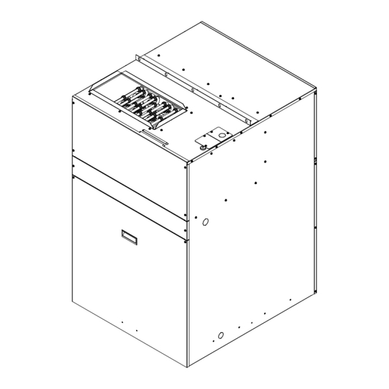
– FIRST-PAK LOCATION OF MAJOR COMPONENTS FIGURE 26 - Slide-Out Chassis Assembly FIGURE 27 - Electric Heater Assembly (15 kW) FPE SERIES – IOM (REV. E 3/24) -
Page 29: Wiring Diagrams
– FIRST-PAK WIRING DIAGRAMS FPE SERIES – IOM (REV. E 3/24) - Page 30 – FIRST-PAK WIRING DIAGRAMS FPE SERIES – IOM (REV. E 3/24)
- Page 31 – FIRST-PAK WIRING DIAGRAMS FPE SERIES – IOM (REV. E 3/24)
- Page 32 – FIRST-PAK WIRING DIAGRAMS FPE SERIES – IOM (REV. E 3/24)
- Page 33 – FIRST-PAK WIRING DIAGRAMS FPE SERIES – IOM (REV. E 3/24)
- Page 34 – FIRST-PAK WIRING DIAGRAMS FPE SERIES – IOM (REV. E 3/24)
- Page 35 – FIRST-PAK WIRING DIAGRAMS FPE SERIES – IOM (REV. E 3/24)
- Page 36 – FIRST-PAK WIRING DIAGRAMS FPE SERIES – IOM (REV. E 3/24)
- Page 37 – FIRST-PAK FPE SERIES – IOM (REV. E 3/24)
-
Page 38: Circuit Schematic
– FIRST-PAK CIRCUIT SCHEMATIC FIGURE 36 - Circuit Diagram STARTUP INSTRUCTIONS PRE-STARTUP CHECKS: PRIOR TO THE STARTUP OF THE UNIT: 1. Ensure supply voltage matches nameplate data. WARNING 2. Ensure the power cable is connected to the unit and the ground cable is connected to the ground lug of Electrically ground the unit. -
Page 39: Heating
– FIRST-PAK STARTUP INSTRUCTIONS STARTUP & PERFORMANCE CONTINUED CHECKLIST INSTRUCTIONS 11. For 208 voltage power, make sure the line voltage Follow the Startup and Performance Checklist on Page 48 and Page 49 to check if the temperature and refrigerant tap on the 24 Volt control transformer has been pressure are normal, and if compressor and fan are running moved and rewired. -
Page 40: Troubleshooting
– FIRST-PAK TROUBLESHOOTING HEATING PROBLEM POSSIBLE CAUSE CHECKS & CORRECTIONS Power is not turned on Turn on the power Check the wiring with the wiring diagram and check for loose Wiring is incorrect or loose wiring connections NO HEAT Thermostat setpoint is too low Set the temperature higher than current room temperature Fuse link is open Replace fuse... -
Page 41: Cooling
– FIRST-PAK TROUBLESHOOTING CONTINUED COOLING PROBLEM POSSIBLE CAUSE CHECKS & CORRECTIONS Power supply off Apply power; close disconnect. Blown Fuse Replace fuse or reset circuit breaker. Check for correct fuses. If voltage is below minimum voltage specified on unit data plate, Voltage supply low contact power company. -
Page 42: Cooling
– FIRST-PAK MAINTENANCE & SERVICE – HEATING CONTINUED FUSE LINK REPLACEMENT 5 kW heater has one heating element. 7 kW and 10 kW heaters have two heating elements. 15 kW heater has three 5 kW heating elements. Each heating element is installed with one non-resettable fuse link (see FIGURE 25 - Non-resettable Fuse Link). - Page 43 – FIRST-PAK MAINTENANCE & SERVICE – HEATING CONTINUED 5) Put the heating element back to the unit, install the screws and connect the wires. NOTE: When putting the heating element back to the unit, make sure the rod is inserted into the hole on the heater support panel.
- Page 44 – FIRST-PAK MAINTENANCE & SERVICE – COOLING CONTINUED AIR CONDITIONER MODULE REMOVAL CONTINUED 2) Remove power cable from unit. 3) Disconnect low voltage (6 pin) & line voltage (3 pin) harness connectors by pressing on the release tabs and using a downward motion (FIGURE 44 - Line Voltage Connector (3 Pin ) &...
- Page 45 – FIRST-PAK MAINTENANCE & SERVICE – COOLING CONTINUED AIR CONDITIONER MODULE REASSEMBLY 1) To put-back the chassis, make sure all the For any other refrigeration servicing, the refrigeration chassis can be removed as explained in REMOVAL OF AC refrigerant lines are in place and there are no Section leaks.
-
Page 46: Replacement Parts
– FIRST-PAK REPLACEMENT PARTS Part Name Part Number Model Use Part Name Part Number Model Use Part Name Part Number Model Use FPE05E1012C 315-18-1 FPE05E1018C 5kW Heat Assm CO120KAB FPE**E1012C Indoor Fan Wheel All FPE Models QTY 1 FPE05E1024C FPE05E1030C FPE07E1012C 315-18-1 FPE07E1018C... -
Page 47: Startup & Performance Checklist
– FIRST-PAK STARTUP & PERFORMANCE CHECKLIST CUSTOMER STARTUP DATE JOB # ADDRESS SERVICING COMPANY TECHNICIAN MODEL # SERIAL # PHONE # INSTALLATION CHECK LIST Inspect the unit for transit damage and report any damage on the carrier’s freight bill. Check model number to insure it matches the job requirements. Install field accessories and unit adapter panels as required. - Page 48 – FIRST-PAK STARTUP & PERFORMANCE CHECKLIST CONTINUED UNIT OPERATION HEATING MODE 1 ELECTRIC HEATER AMPS 2 INDOOR BLOWER AMPS 3 TEMPERATURE RISE Supply Duct Temperature – Return Duct Temperature Temperature Rise 4 TOTAL EXTERNAL STATIC Supply Duct Temperature Return Duct Temperature Temperature Rise COOLING MODE 5 INDOOR BLOWER AMPS...
- Page 49 P.O. Box 270969 Dallas, TX 75227 www.firstco.com or www.ae-air.com The manufacturer works to continually improve its products. It reserves the right to change design and specifications without notice. ©2023 First Co., Applied Environmental Air...
Need help?
Do you have a question about the First-Pak AC FPE Series and is the answer not in the manual?
Questions and answers