Table of Contents
Advertisement
Quick Links
Installation, Operation, & Maintenance Manual
IOM 8401
Rev. A 09/21
FPG SERIES
Vertical Packaged Gas Heat / Electric Cooling Unit
Category III Type MSP
ATTENTION
:
Installer
Affix these instructions on or adjacent to the furnace.
Consumer
Read these instructions thoroughly and retain all manuals
for future reference.
FIRE OR EXPLOSION HAZARD
Failure to follow safety warning exactly could result in
serious injury, death or property damage.
– Do not store or use gasoline or other flammable vapors
and liquids in the vicinity of this or any other appliance.
– WHAT TO DO IF YOU SMELL GAS
Do not try to light any appliance.
Do not touch any electrical switch; do not use any
phone in your building.
Leave the building immediately.
Immediately call your gas supplier from a neighbor's
phone. Follow the gas supplier's instructions.
If you cannot reach your gas supplier, call the fire
department.
– Installation and service must be performed by a qualified
installer, service agency or the gas supplier.
Advertisement
Table of Contents

Related Manuals for First Co FIRST-PAK FPG Series


Summary of Contents for First Co FIRST-PAK FPG Series
- Page 1 Installation, Operation, & Maintenance Manual IOM 8401 Rev. A 09/21 FPG SERIES Vertical Packaged Gas Heat / Electric Cooling Unit Category III Type MSP ATTENTION Installer Affix these instructions on or adjacent to the furnace. Consumer Read these instructions thoroughly and retain all manuals for future reference.
- Page 2 FIRST-PAK IOM COPYRIGHT First Co. works to continuously improve its products and as a result, it reserves the right to change design and specifications without notice. The warranty may be void unless the Startup & Performance Checklist is completed and returned to the warrantor. If the FIRST- PAK Gas Furnace unit is not installed properly, the warranty will be void, as the manufacturer cannot be held accountable for problems that stem from improper installation.
-
Page 3: Table Of Contents
FIRST-PAK TABLE OF CONTENTS SAFETY CONSIDERATIONS MODEL NOMENCLATURE GENERAL INFORMATION INTRODUCTION STORAGE SHIPPING & PACKAGE LIST UNIT INSPECTION CHECKLIST UNIT DIMENSIONAL DATA UNIT PHYSICAL DATA ELECTRICAL DATA INSTALLATION 13-25 REQUIREMENTS INSTALLATION PRECAUTIONS 13-14 UNIT LOCATION UNIT CLEARANCE REQUIREMENTS VENT CLEARANCES REMOVAL OF A UNIT FROM A COMMON VENTING SYSTEM WALL SLEEVE INSTALLATION UNIT SUPPORT... -
Page 4: Safety Considerations
FIRST-PAK IOM SAFETY CONSIDERATIONS 1. READ THE ENTIRE MANUAL BEFORE STARTING THE INSTALLATION. 2. These instructions are intended as a general guide and do not supersede national, state, or local codes in any way. 3. Altering the product, improper installation, or the use of unauthorized factory parts voids all warranty or implied warranty and may result in adverse operation and/or performance or may result in hazardous conditions to service personnel and occupants. - Page 5 FIRST-PAK SAFETY CONSIDERATIONS CONTINUED 10. This furnace is equipped with a blocked vent shut-off SAFETY RULES: system. If the furnace fails to operate, contact a qualified 1. This furnace is approved for use with Natural Gas only. service agency for repair. Refer to the FURNACE RATING PLATE.
- Page 6 FIRST-PAK IOM SAFETY CONSIDERATIONS CONTINUED 13. The following items should be inspected annually (minimum) before each heating season by a qualified service agency: a. HEAT EXCHANGER TUBES; make sure they are free from blockages, signs of carbon buildup or heavy Disconnect all power before servicing.
-
Page 7: Model Nomenclature
DIGITS 13-15 – OPTIONS 000 – NONE DIGITS 6-7 – HEAT CONFIGURATION N8 – Natural Gas Non-Condensing DIGIT 16 – BRAND F – First Co. DIGIT 8 – UNIT TYPE C – Cooling Only FPG SERIES – IOM (REV. A 09/21) -
Page 8: General Information
FIRST-PAK IOM GENERAL INFORMATION This furnace is designed for through-the-wall indoor installation only. Installation of this equipment, wiring, ducts, and any related components must conform to DO NOT use these units as a source of heating or cooling current agency codes, state laws, and local codes. Such during the construction process. -
Page 9: Storage
FIRST-PAK STORAGE Equipment should be stored in a clean dry, conditioned NOTE: CONDENSER COIL SHRINK WRAP AROUND UNIT area with maximum temperatures up to 120°F [48.89°C] PROTECTION PAD and minimum temperatures to 32°F [0°C]. Units should be TRAY COVER stored upright and in an indoor environment. It is EVAPORATOR COIL recommended to leave packaging on the unit until the PROTECTION PAD... -
Page 10: Unit Inspection Checklist
FIRST-PAK IOM UNIT INSPECTION CHECKLIST Complete the inspection procedures below before preparing unit for installation: 1) Visually inspect unit for any shipping damage. Damage must be reported immediately to the shipping company to make a claim. 2) Ensure that the carrier makes proper notation of any shortages or damage on all copies of the freight bill PALLET and completes a common carrier inspection report. -
Page 11: Unit Dimensional Data
FIRST-PAK UNIT DIMENSIONAL DATA HIGH VOLTAGE VOLTAGE 1.34" SUPPLY SUPPLY [34] 3.06" 9.92" [78] [252] 3.75" [95] GAS INLET 2.75" 1.94" GAS INLET [70] [49] FPG60N8* Only 15.42" [392] 8.00" 1.00" 16.00" [203] [25] [406] 2.96" [75] 43.19" [1097] 31.38" 27.88"... -
Page 12: Unit Physical Data
FIRST-PAK IOM UNIT PHYSICAL DATA PHYSICAL DATA FPG MODELS 20N8C09A 20N8C12A 30N8C12A 40N8C12A 30N8C18A 40N8C18A 50N8C18A 60N8C18A UNIT INFORMATION Compressor Type (Qty) Rotary (1) Rotary (1) Rotary (1) Rotary (1) Rotary (1) Rotary (1) Rotary (1) Rotary (1) Factory Charge (R410A) lbs. [kg] 3.7 [1.7] 3.9 [1.8] 3.9 [1.8]... -
Page 13: Electrical Data
FIRST-PAK ELECTRICAL DATA ELECTRICAL DATA CONDENSOR INDOOR MIN. MAX. COMPRESSOR MIN. MAX. MODEL NUMBER VOLTAGE-PH-HZ MOTOR MOTOR CIRCUIT CIRCUIT VOLTAGE VOLTAGE AMPACITY PROTECTION FPG20N8C09A* 208/230-1-60 FPG20N8C12A* 208/230-1-60 FPG30N8C12A* 208/230-1-60 FPG40N8C12A* 208/230-1-60 FPG30N8C18A* 208/230-1-60 FPG40N8C18A* 208/230-1-60 FPG50N8C18A* 208/230-1-60 FPG60N8C18A* 208/230-1-60 FPG30N8C24A* 208/230-1-60 10.7 FPG40N8C24A*... -
Page 14: Unit Location
FIRST-PAK IOM INSTALLATION CONTINUED INSTALLATION PRECAUTIONS CONTINUED UNIT LOCATION This furnace is certified for through-the-wall, indoor, up- flow vertical position installation only. This appliance is not design certified for installation in mobile homes, When the unit is in operation components are rotating at recreational vehicles, or outdoors. -
Page 15: Unit Clearance Requirements
FIRST-PAK INSTALLATION CONTINUED UNIT CLEARANCE REQUIREMENTS Min. 2” The unit may be installed with zero clearances to adjacent Req’d combustible surfaces. This furnace shall not be installed directly on carpeting, tile, or other combustible material, other than wood flooring. Service clearance must be provided for future maintenance and service. -
Page 16: Vent Clearances
FIRST-PAK IOM INSTALLATION CONTINUED VENT CLEARANCES FIGURE 9 - Location of Vent Termination Clearances VENT TERMINATION CLEARANCES CLEARANCE CANADIAN INSTALLATIONS¹ US INSTALLATIONS² A = Clearance above grade, veranda, porch, deck, or 12 in (30 cm) 12 in (30 cm) balcony (see 1.23.5-i(9)b.) B = Clearance to window or door that may be opened 6 in (15 cm) for appliances 10,000 Btuh (3 kW) 12 in (30cm) for appliances >10,000 Btuh(3 kW) -
Page 17: Removal Of A Unit From A Common Venting System
FIRST-PAK INSTALLATION CONTINUED REMOVAL OF A UNIT FROM A COMMON VENTING SYSTEM When an existing furnace is removed from a common venting system serving other appliances, the venting system is likely to be too large to properly vent the Disconnect all power supplies before servicing. -
Page 18: Wall Sleeve Installation
FIRST-PAK IOM INSTALLATION CONTINUED WALL SLEEVE INSTALLATION REAR INSTALLATION & DIMENSIONS Refer to installation instruction packed with the wall sleeve to assemble and mount into the wall. Before unit 0” Min. installation, make sure sleeve components are not damaged; drain line is not obstructed and is leak free. Check all seals to ensure that they are in position and un- damaged. -
Page 19: Unit Support
FIRST-PAK INSTALLATION CONTINUED Things to consider prior to build the support structure: UNIT SUPPORT 1. Accurately measure the unit and choose a strong The First Pak wall sleeve is not intended or designed to building material for the support structure. provide complete support for the First Pak unit. -
Page 20: Packaged Unit Installation
FIRST-PAK IOM INSTALLATION CONTINUED PACKAGED UNIT INSTALLATION FIGURE 13 - FIRST-PAK Unit Installation Insulation is installed in indoor equipment to provide a barrier between outside air conditions surrounding the unit and the varying conditions inside the unit. If the insulating Locate the unit in an area that provides minimum barrier is damaged, the surrounding ambient air will affect clearance to all service access panels. - Page 21 FIRST-PAK INSTALLATION CONTINUED 7. Inspect the sleeve seal, which is supplied with the PACKAGED UNIT INSTALLATION sleeve, to ensure that it is properly secured and aligned (see FIGURE 14 – Wall Sleeve Seal 8. Slide the FIRST-PAK unit toward the sleeve seal Check nameplate voltage, amperage and fuse size for until the sleeve and cabinet brackets are nested proper power supply.
-
Page 22: Ductwork
FIRST-PAK IOM INSTALLATION CONTINUED DUCTWORK Both supply and return air ducts must be attached to the unit. The supply duct connection must be sized to a minimum of the same size as the unit discharge air opening. All ductwork must be installed in accordance with National Fire Protection Assoc. -
Page 23: Venting
FIRST-PAK INSTALLATION CONTINUED VENTING AIR FILTER The venting system exhausts the products of combustion to The First Pak unit must not be operated without an air filter the outdoors. The venting system is an integral part of the in place. The unit is equipped with a factory installed 1” furnace and must not be altered. -
Page 24: Combustion Air
FIRST-PAK IOM INSTALLATION CONTINUED COMBUSTION AIR GAS PIPING & CONNECTION This is a direct vent furnace, which receives its combustion All gas piping and connections to this furnace must be air from outside and discharges the products of performed by a qualified installer. Installation methods and combustion outside. -
Page 25: Leak Testing
FIRST-PAK INSTALLATION CONTINUED The furnace and its external gas shut-off valve must be GAS PIPING & CONNECTION CONTINUED disconnected from the piping system before any gas line When installing an FPG60, which is replacing a competitors pressure test exceeding ½ PSI (14” [35.56cm] W.C.) is unit, field installed gas piping may require an offset to line performed. -
Page 26: Electrical
FIRST-PAK IOM ELECTRICAL HIGH VOLTAGE LOW VOLTAGE THERMOSTAT A standard 24 VAC single state heating and cooling thermostat is required to control this unit. A thermostat with a “C” common terminal is preferred. Thermostat Disconnect all power supplies before servicing. Lock connections and their functions are below in FIGURE 22 - out/tag out to prevent accidental electrical shock. -
Page 27: Controls
FIRST-PAK CONTROLS CONTROL BOARD FIGURE 23 - Control Board SIGNAL PROBLEM POSSIBLE CAUSE CHECKS & CORRECTIONS Slow Flash No heat request from room thermostat Stand-by mode; does not indicate fault condition RAPID FLASH Room thermostat is requesting heat Thermostat requesting heat; does not indicate condition CONSTANT OFF Internal fault or No power Main power is off or control has failed... - Page 28 FIRST-PAK IOM CONTROLS CONTINUED CONTROL BOARD RELAY TRANSFORMER CONTACTOR TERMINAL STRIP CAPACITOR FIGURE 24 – Electrical Components LED LIGHT FIGURE 25 - Control Bracket Detail FPG SERIES – IOM (REV. A 09/21)
- Page 29 FIRST-PAK CONTROLS CONTINUED BLOWER CONTROL FPG gas heat units are equipped with a direct drive indoor blower motor. FPG**N8C09A and FPG**N8C12A have a blower motor with 4 speeds: Either T2 or T3 may be used for heating mode providing the speed selection allows the unit to operate within specified temperature rise range.
- Page 30 FIRST-PAK IOM PERFORMANCE DATA FPG AIRFLOW PERFORMANCE DATA IWC STATIC PRESSURE MOTOR RISE MODEL SPEED RISE °F RANGE °F TEMP TEMP TEMP TEMP TEMP SCFM SCFM SCFM SCFM SCFM RISE °F RISE °F RISE °F RISE °F RISE °F 25-55 25-55 FPG20N8C09A* 40.0...
- Page 31 FIRST-PAK PERFORMANCE DATA FPG AIRFLOW PERFORMANCE DATA IWC STATIC PRESSURE MOTOR RISE MODEL SPEED RISE °F RANGE °F TEMP TEMP TEMP TEMP TEMP SCFM SCFM SCFM SCFM SCFM RISE °F RISE °F RISE °F RISE °F RISE °F 30-60 30-60 FPG30N8C24A* 45.0 30-60...
-
Page 32: Heating Operations
FIRST-PAK IOM HEATING OPERATIONS FIGURE 27 - Heating Sequence of Operations FPG SERIES – IOM (REV. A 09/21) - Page 33 FIRST-PAK HEATING OPERATIONS CONTINUED TO LIGHT BURNERS 1. Turn off electrical power to the unit. 2. Turn the room thermostat to the lowest setting. 3. Check that the position of the gas valve switch is in the “on” position (see FIGURE 29 –...
- Page 34 FIRST-PAK IOM HEATING OPERATIONS CONTINUED GAS SUPPLY PRESSURE 1. Turn “off” the gas supply to the furnace using the ¼ turn manual gas valve. GAS VALVE IN “ON” 2. Turn the pressure test screw (3/32" Hex) in the POSITION center of the inlet pressure boss not more than one turn counterclockwise.
-
Page 35: Cooling Operations
FIRST-PAK HEATING OPERATIONS CONTINUED TEMPERATURE RISE This gas furnace is designed to operate within a specific range of temperatures while in heating mode. The “Temperature Rise” range is shown on the rating plate. MEASURE SUPPLY TEMP Temperature rise is defined as the temperature difference between the air entering the furnace and the air leaving SUPPLY AIR FLOW... -
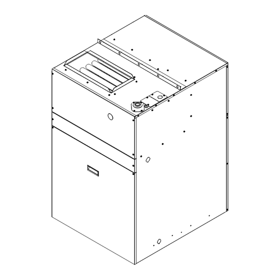
Page 36: Location Of Major Components
FIRST-PAK IOM LOCATION OF MAJOR COMPONENTS HEAT EXCHANGER ASSEMBLY CONDENSER COILASSEMBLY BLOWER FAN ASSEMBLY CHASSIS SLIDE-OUT COOLING ASSEMBLY FILTER RETENTION EVAPORATOR COIL ASSEMBLY DRAIN PAN FIGURE 33 – Slide Out Chassis Assembly MANIFOLD DRA FT INDUCER GAS VALVE FIGURE 34 – Heating Assembly FPG SERIES –... - Page 37 FIRST-PAK LOCATION OF MAJOR COMPONENTS CONTINUED SUPPLY AIR DUC T LINE VOLTAGE CONNECTION KNOCKOU T FLUE PIPE GAS INLE T VOLTAGE COMPRESSOR FIGURE 35 – Cabinet Components FPG SERIES – IOM (REV. A 09/21)
-
Page 38: Wiring Diagrams
FIRST-PAK IOM WIRING DIAGRAMS FPG SERIES – IOM (REV. A 09/21) - Page 39 FIRST-PAK WIRING DIAGRAMS FPG SERIES – IOM (REV. A 09/21)
- Page 40 FIRST-PAK IOM WIRING DIAGRAMS FPG SERIES – IOM (REV. A 09/21)
- Page 41 FIRST-PAK WIRING DIAGRAMS FPG SERIES – IOM (REV. A 09/21)
-
Page 42: Circuit Diagrams
FIRST-PAK IOM CIRCUIT SCHEMATIC FIGURE 40 - Circuit Diagram STARTUP INSTRUCTIONS PRE-STARTUP CHECKS: PRIOR TO THE STARTUP OF THE UNIT: 1. Ensure supply voltage matches nameplate data. 2. Ensure the unit is properly grounded. 3. With the power off, check blower wheel set screws Electrically ground the unit. - Page 43 FIRST-PAK STARTUP INSTRUCTIONS CONTINUED Example of input rate calculation using the typical heating UNIT STARTUP: valve of Natural Gas of 1,000 BTU cu/ft, and 90 seconds 1. Ensure that power is connected to the unit and the time to complete one revolution of the 1 cu/ft dial on the local disconnect is switched to ON position.
-
Page 44: Troubleshooting
FIRST-PAK IOM TROUBLESHOOTING HEATING PROBLEM POSSIBLE CAUSE CHECKS & CORRECTIONS Open Circuit Fuse (Electrical Panel) Replace fuse Open Circuit Breaker (Electrical Panel) Re-set circuit breaker / fuse NO OPERATION Open Unit Power Switch Check position / electrical state of switch (External disconnect, adjacent to unit) Refer to LED &... -
Page 45: Heating
FIRST-PAK TROUBLESHOOTING CONTINUED HEATING Step 1 Thermostat calls for heat by energizing “W” terminal with 24 volts a/c Description The room thermostat R terminal is constantly powered with 24 volts a/c by its connection to the control board R terminal and the unit transformer. A request for heat will energize the “W” terminal of the thermostat and the control board. - Page 46 FIRST-PAK IOM TROUBLESHOOTING CONTINUED HEATING Step 6 Control board energizes the spark ignitor & the gas valve (trial for ignition) Description During trial for ignition, the draft inducer, & gas valve are energized. After 10 seconds, the spark ignitor is de- energized &...
-
Page 47: Cooling
FIRST-PAK TROUBLESHOOTING CONTINUED COOLING PROBLEM POSSIBLE CAUSE CHECKS & CORRECTIONS Power supply off Apply power; close disconnect. Blown Fuse Replace fuse or reset circuit breaker. Check for correct fuses. If voltage is below minimum voltage specified on unit data plate, Voltage supply low ENTIRE UNIT contact power company. - Page 48 FIRST-PAK IOM MAINTENANCE & SERVICE - HEATING AIR FILTER(S) COMBUSTION AIR PROVING SWITCH Furnace filters should be checked monthly and replaced as The combustion air-proving switch is a safety device which necessary. Do not operate the furnace without filters in verifies operation of the combustion blower and that the place.
- Page 49 FIRST-PAK MAINTENANCE & SERVICE – HEATING CONTINUED INDOOR BLOWER MOTOR PERIODIC INSPECTIONS Check the openings on the end of the indoor blower motor The following items should be inspected annually to make sure they are not blocked and free from debris. (minimum) before each heating season by a qualified The indoor blower motor contains permanently sealed ball service agency:...
- Page 50 FIRST-PAK IOM MAINTENANCE & SERVICE – HEATING CONTINUED HEATING MODULE REMOVAL The entire gas heat section may be removed as a unit for service if required. Turn off electrical power to furnace. 1) Turn off electrical power to furnace. 2) Remove heating section access panels as seen in FIGURE 43 –...
- Page 51 FIRST-PAK MAINTENANCE & SERVICE – COOLING AIR CONDITIONER MODULE REMOVAL The air-conditioning chassis may be removed as a unit for service if required. Turn off electrical power to refrigeration chassis. 1) Remove screws (2) from controls cover and remove panel. See FIGURE 45 –...
- Page 52 FIRST-PAK IOM MAINTENANCE & SERVICE – COOLING CONTINUED AIR CONDITIONER MODULE REASSEMBLY FILTER 1) To put-back the chassis, make sure all the refrigerant The air filter should be cleaned or replaced every 30 days lines are in place and there are no leaks. or more frequently if severe operating conditions exist.
-
Page 53: Support Material
FIRST-PAK SUPPORT / REFERENCE MATERIAL CALCULATION ABBREVIATIONS = British Thermal Unit = Airflow rate cubic feet per minute = Thermal Efficiency ᴮᵀᵁ/hr = Rated input of furnace Acm² = Cross-sectional area of test duct in cm² = the midpoint of the specified range Δ... -
Page 54: Startup & Performance Checklist
FIRST-PAK IOM STARTUP & PERFORMANCE CHECKLIST FIGURE 50 - Startup and Performance Checklist (1 of 2) FPG SERIES – IOM (REV. A 09/21) - Page 55 FIRST-PAK STARTUP & PERFORMANCE CHECKLIST CONTINUED FIGURE 51 - Startup and Performance Checklist (2 of 2) NOTES FPG SERIES – IOM (REV. A 09/21)
- Page 56 Manufactured by: 8273 Moberly Lane Dallas, TX 75227 www.firstco.com The manufacturer works to continually improve its products and as a result, it reserves the right to change design and specifications without notice. ©2021 First Co., 8273 Moberly Lane, Dallas, TX 75227...
Need help?
Do you have a question about the FIRST-PAK FPG Series and is the answer not in the manual?
Questions and answers