Table of Contents
Advertisement
Quick Links
DO NOT
HANDHELD
THIS TOOL
USE MANUAL and SPARE PARTS
IMPORTANT DO NOT DESTROY !
Read carefully this manual before using the tool and
respect the security norms herewith enclosed.
Via Foresto 42 - 31058 SUSEGANA TV ITALY
®
80.16 ROC21
Tel.0438455318 Fax 0438455530
cod. 11560ROC21
11560ROC21_8016ROC21_5 31102023 DV
E-mail: omer@omer.it
MADE
IN
ITALY
www.omer.it
Advertisement
Table of Contents

Subscribe to Our Youtube Channel
Related Manuals for Omer 11560ROC21


Summary of Contents for Omer 11560ROC21
- Page 1 ® 80.16 ROC21 cod. 11560ROC21 DO NOT MADE HANDHELD ITALY THIS TOOL USE MANUAL and SPARE PARTS IMPORTANT DO NOT DESTROY ! Read carefully this manual before using the tool and respect the security norms herewith enclosed. 11560ROC21_8016ROC21_5 31102023 DV Via Foresto 42 - 31058 SUSEGANA TV ITALY Tel.0438455318 Fax 0438455530...
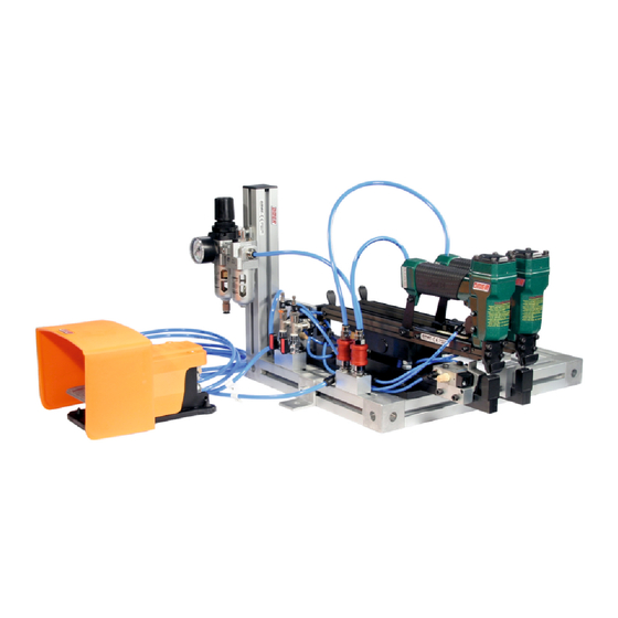
- Page 2 INTRODUCTION: The bench-mounted ROC2 is the optimal solution for fixing 2 staples simultaneously. Ideal for fastening blister, bags, boxes, displaying cards, etc. Features: • Frame with aluminium profile, easy to fix upon working surface •Pneumatic system complete with FRL unit and manometer for a correct power supply •...
- Page 3 - 2 -...
-
Page 4: Table Of Contents
INDEX: Introduction ......................1 Nomenclature ......................2 Index ........................3 Declaration of conformity User manual and safety rules Warranty ....4 - 9 Technical data ......................10 - 11 Operating modes: - Single mode ............12 - Dual mode ............13 Settings (to do in sequence): - Stapling position ...... -
Page 5: Introduction
INTRODUCTION In order to assure top working reliability, OMER has made a careful choice of the materials and components to be used in the manufacture of the tool and has tested it before delivery. Proper performance of the tacker in time also depends on its correct use and on adequate servicing according to the instructions contained in this manual. - Page 6 OMER spa does not answer for damage to the gun due to the use of staples or nails of types not suitable for the model.
- Page 7 To do so, unscrew the head screws with the hex spanner supplied, open the gun and remove the different components. Check carefully the state of wear of the O-rings and of the rubber parts. Replace the worn parts with OMER original spare parts.
- Page 8 INTRODUCTION In order to assure high reliability, OMER has made a careful choice of the materials and components to be used in the manufacturing process of the tool and has tested it before delivery. Proper performance of the tacker in time also depends on its correct use and on adequate servicing according to the instructions contained in this manual.
- Page 9 OMER spa does not answer for damage to the gun due to the use of staples or nails of types not suitable for the model.
- Page 10 To do so, unscrew the head screws with the hex spanner supplied, open the gun and remove the different components. Check carefully the state of wear of the O-rings and of the rubber parts. Replace the worn parts with OMER original spare parts.
-
Page 11: Technical Data
Technical data Suitable staple series : Stapling results 98.06 (standard supplied) 0,65x0,95 staple 1/4" 5/8" 11,4 Crown: .500” (1/2“) Thickness: .025" Width: .037" Gauge: Usable lenghts mm 6÷16 1/4"÷5/8" Usable lengths inch Magazine capacity No. of fasteners 5,5÷6,5 Working pressure bar Working pressure psi 80÷95 0,68... - Page 12 Technical data Main tool Max 18 Max 10 15,5 Min 0,5 27,5 105,5 160,5 Secondary tool Max 18 Max 10 15,5 Min 0,5 27,5 142,5 160,5 min 60 Max 504 *all measures are expressed in mm - 11 -...
- Page 13 Operating Modes Singole Mode : Single mode is used when the fastening of only one staple at a time is required. To set this mode follow the istructions: This mode can be activated only on the main tool 1 - Close the ball valve 2 - Close the slide valve (by closing you will notice a brief air flow) Operating Mode :...
-
Page 14: Operating Modes: - Single Mode
Operating Modes Dual Mode : The dual mode is required when two staples are to be fired at the same time. To set this mode follow the istructions : 1 - Both ball valves must be open 2 - Both slide valves must be open Operating Mode :... - Page 15 How to set stapling position r a x n t e o f i l e s t a p t i n g S e t w e e b e t n c e i s t a o f d e n t e d g...
- Page 16 How to set stapling position Adjustment of distance from the edge : The distance from the edge is determined by the adjustment of the spacerssituated on the two staplers. Main stapler: 1 - Losen the screws. 2 - Slide the spacer along the guide until required position.
- Page 17 Adjustment of front side opening A front side opening adjustment must be carried out to allow an easy insertion of the material to be fastened. Disconnect the air before proceeding with any adjustment 1 - Press the stapler head and hold this position to have access to the pneumatic cylinder and bumper.
-
Page 18: Clinching Depth
Adjustment of clinching depth To avoid flattening/damaging the material to be fastened it is possible to set the clinching depth by adjusting the end-run screw Disconnect the air before proceeding with any adjustment max 10 mm min 0,5 mm 1 - Loosen the nut which stops the end-run screw 2 - Screw or unscrew the end-run screw to adjust the clinching depth 3 - Tighteen the locking nut... -
Page 19: Clinching Speed
Clinching speed adjustment This adjustment allows you to set the most comfortable working speed. An excess of speed identifiable in too sudden movements of the stapler may lead to early wearing out. Main stapler To increase clinching speed To decrease clinching speed To increase opening speed To decrease opening speed Secondary tool... -
Page 20: Fire Delay Adjustment
Fire delay adjustment Fire delay adjustment is the more necessary the wider is the front opening on the tool, since you must give time to the stapler to block the material before firing. Main stapler: Delays firing Anticipates firing Secondary tool: Delays firing Anticipates firing - 19 -... - Page 21 Adjustment of working cycle This adjustment fixes the lengt of the working cycle, which starts with the activation of the control lever and stops by releasing the fastened material Working cycle time is adjusted by acting on timer as follow: The best performance of the tool is achieved by syncronizing clinching speed, firing delay and tool return time 1 - Use a screw driver to rotate the selector marked with an...
-
Page 22: Loading
Loading DO NOT press pedal while loading, to avoid activating the device 1 - Pull the pusher backwards and lock it at the stop position at the rear of the tool, this will open the movable hold down 2 - Load staples 3 - Release the slider - 21 -... -
Page 23: Jam-Clearing
Jam -clearing In case of jamming proceed as follow: 1 - Pull the pusher all the way back and lock it. 2 - Remove the staple from magazine. 3 - Open the slider closing trigger. 4 - Pull the slider all the way back by pulling the pusher further backwards and hold it. 5 - Pull out the jammed staple from the driving channel. - Page 24 Spare parts 04.35 92.01X 00.12 25.04 01.33 40.04.2 39.00 00.14 01.29 22.07 24.00 00.26 17.31.4 28.00 45.04 00.35 20.00 01.21.1 30.07.3 01.21.3 03.00 14.18.1 66.03 22.00.80-1685 50.06.1 00.35 17.30.5 00.14 66.03 26.07 00.06 52.02 03.30 00.27 91.08 50.03 54.04 32.05 00.04 09.02 00.13...
- Page 25 Spare parts 04.35 98.08 17.31.8 17.31.6 05.30 18.54 18.51 32.05 17.36.4 06.19 04.35 B(V) 17.37.2 17.31.6 06.00.3 17.38 17.37.7 18.02 05.30 06.20 32.05 06.19 B(V) 98.04 17.37.2 06.00.3 98.03 17.38 98.01 18.02 92.03 98.07.1 05.12 06.20 05.20 98.04 98.03 98.01 98.05.2 92.03 05.25...
- Page 26 Spare parts 17.37.1 A(C) 17.38 Connetion tubes 17.37.2 B(V) 17.38 17.39.8 18.25 ø 17.37.1 A(C) 17.38 17.39.8 Ø 17.30.6 17.38 17.37.2 18.25.1 B(V) 18.25 17.31.4 17.31.6 17.14 17.34.2 17.34.8 18.24 17.31.4 00.14 18.24 18.24 18.22.1 17.31.8 18.21 17.31.4 MATRICOLA SERIAL NUMBER MATRICULE MATRICULA INDICE DI MODIFICA...
- Page 27 Accessories Available anvil 98.06 (standard supplied) staple 98.06-780 (on request) 07.50 07.40 staple 07.30 07.25 O-Rings 01.21.3 00.27 01.21.1 28.00 00.70.5 00.35 01.33 01.29 00.26 01.10 00.14 00.12 00.13 00.06 00.04 80.16 ROC21 Upgrade c o d . 1 1 5 6 0 R O C 2 1 number - 26 -...
-
Page 28: Spare Parts List
Spare part list Cod. Descrizione Description Cod. Descrizione Description 00.04 O-Ring O-Ring 18.22.1 Filtro riduttore lubrificatore Reducer group 00.06 O-Ring O-Ring 18.24 Distributore Distributor 00.12 O-Ring O-Ring 18.25 Valvola a sfera Ball valve 00.13 O-Ring O-Ring 18.25.1 Valvola a corsoio Sliding valve 00.14 O-Ring... -
Page 29: Pneumatic Diagram
B(V) B(V) Ø4 Ø4 Ø4 Ø4 Ø6 Ø6 Ø4 A(C) B(V) A(C) B(V) Ø4 Ø4 Ø6 Ø6 R P S Ø6 5,5 ÷ 6,5 bar Ø6 Pneumatic diagram - 28 -... - Page 30 Note - 29 -...
Need help?
Do you have a question about the 11560ROC21 and is the answer not in the manual?
Questions and answers