Metrologic MS9500 Voyager series Installation And User Manual
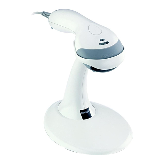
Ms9500 voyager series single-line hand held laser scanner
Hide thumbs
Also See for MS9500 Voyager series:
- Installation and user manual (56 pages) ,
- Product manual (6 pages) ,
- Specification sheet (2 pages)
Table of Contents
Advertisement
Advertisement
Table of Contents

Related Manuals for Metrologic MS9500 Voyager series


Summary of Contents for Metrologic MS9500 Voyager series
- Page 2 Copyright © 2005 by Metrologic Instruments, Inc. All rights reserved. No part of this work may be reproduced, transmitted, or stored in any form or by any means without prior written consent, except by reviewer, who may quote brief passages in a review, or provided for in the Copyright Act of 1976.
-
Page 3: Table Of Contents
ABLE OF ONTENTS Introduction ......................1 Scanner and Accessories ..................2 Installing the Scanner to the Host System RS232, OCIA, Laser Emulation, and Light Pen Emulation........4 IBM 46xx ......................5 Keyboard Wedge ....................6 Stand Alone Keyboard..................7 Integrated USB Full Speed......................8 Low Speed.....................8 The PowerLink Cable Disconnecting ....................9 Connecting......................9 ®... - Page 4 ABLE OF ONTENTS IR Activation......................25 Applications and Protocols ..................26 Troubleshooting Guide ..................27 RS232 Demonstration Program................30 Design Specifications Operational ......................31 Mechanical.......................32 Electrical ......................32 Environmental ....................32 Default Settings....................33 Scanner and Cable Terminations Scanner Pinout Connections ................38 Cable Connector Configurations..............40 Limited Warranty....................43 Laser and Product Safety ..................44 Patents.........................46 Index ........................47 Contact Information and Office Locations............49...
-
Page 5: Introduction
NTRODUCTION ® Metrologic’s MS9520 Voyager and the MS9540 VoyagerCG are a group of single-line laser bar code scanners that have the ability to decode all standard 1D, RSS-14, RSS Limited and RSS Expanded bar codes. The MS9520 is packed with all of the same features as the MS9540, with the exception of ®... -
Page 6: Scanner And Accessories
MS9520 – xx Voyager or VoyagerCG Bar Code Scanner MS9540 – xx 00-02544 MetroSelect Single-Line Configuration Guide MS9500 Voyager Series Single-Line Hand Held Laser 00-02410 Scanner Installation and User’s Guide Available for download on the Metrologic website - www.metrologic.com PTIONAL... - Page 7 CANNER AND CCESSORIES PTIONAL CCESSORIES Part # Description OCIA PowerLink Cable with Built in Power Jack 53-53015x-3 2.7 m (9 ft.) coiled cord, long strain relief, black USB Power/Communication Cable, Locking Type A 53-53213x -N-3 2.7 m (9 ft.) coiled cord, long strain relief, black USB Power/Communication Cable, Locking Type A 4.5 m (15 ft.) coiled cord, long strain relief, black 53-53214x -N-3...
-
Page 8: Installing The Scanner To The Host System
NSTALLING THE CANNER TO THE YSTEM RS232, OCIA, L ASER MULATION IGHT MULATION MS9520-00/ 9/14 /41 MS9540-00/9/14/ 41 Turn off the host system. Connect the 10-pin RJ45 male connector into the jack on the scanner. You will hear a ‘click’ when the connection is made. -
Page 9: Ibm 46Xx
NSTALLING THE CANNER TO THE YSTEM IBM 46 MS9520-11 MS9540-11 Turn off the host system. Plug the male 10-pin RJ45 end of the MVC cable into the 10-pin socket on the scanner. You will hear a ‘click’ when the connection is made. Connect the other end of the MVC cable to the host device. -
Page 10: Keyboard Wedge
NSTALLING THE CANNER TO THE YSTEM MS9520-47 MS9540-47 EYBOARD EDGE Turn off the host system. Connect the 10-pin RJ45 male connector into the jack on the scanner. You will hear a ‘click’ when the connection is made. Connect the L-shaped plug of the power supply into the power jack on the PowerLink cable. -
Page 11: Stand Alone Keyboard
NSTALLING THE CANNER YSTEM MS9520-47 MS9540-47 TAND LONE EYBOARD Turn off the host system. Connect the 10-pin RJ45 male connector into the jack on the scanner. You will hear a ‘click’ when the connection is made. If the scanner is receiving power from the host system, skip to step #5. -
Page 12: Integrated Usb Full Speed
NSTALLING THE CANNER YSTEM USB: F MS9520-40 MS9540-40 NTEGRATED PEED MS9520-38 MS9540-38 PEED Turn off the host system. Connect the 10-pin RJ45 male connector of the USB cable into the jack on the scanner. You will hear a ‘click’ when the connection is made. Connect the other end of the USB cable to the host USB port. -
Page 13: The Powerlink Cable
OWER ABLE ISCONNECTING THE OWER ABLE Before removing the cable from the scanner, Metrologic recommends that the power on the host system is off and the power supply has been disconnected from the PowerLink cable. Figure 6. Locate the small ‘pin-hole’ on the top of the unit near the bottom of the Voyager logo. -
Page 14: The Ms9540 Voyagercg ® Series
® MS9540 V OYAGER ERIES OW TO ATE AND THE ANUAL CTIVATION ® ANUAL CTIVATION This feature is not a default setting. Refer to the MetroSelect Configuration Guide for instructions on enabling the Manual Activation Mode. Figure 9. Figure 10. HREE ODES OF PERATION... -
Page 15: Stand Kits
TAND Free Standing Kits #46-46128 Contains: a. Stand ( 36-00454) ........ Qty 1 MLPN b. Apron ( 50-50440) ........ Qty 1 MLPN c. Screw, M3 x 6 mm ( 18-18670).... Qty 2 MLPN d. Washer, #5 x .5 OD ( 18-18671).. -
Page 16: Assembly
SSEMBLING THE TAND There are two options for assembling the stand. The first option is a self- supporting stand that can be moved freely about on the countertop. The second option is used if the stand will be bolted or hard-mounted to the countertop. Stand Option 1: Self-Supported Stand Kit #46-46128 Apron Step 1... - Page 17 SSEMBLING THE TAND Stand Option 2: Hard-Mount Kits #46-46128, #46-46351 and MS951 Stand Replacements Anchor from Step 3 Kit #46-46128 Screw the stand anchor ( 50-50449) MLPN Base Assembly from onto the base assembly until it sits flush. Kit #46-46351 or MS951 Stand Base Figure 19.
- Page 18 SSEMBLING THE TAND Wall Mount, Option 1: For Kit #46-46433 or #46-46508 Step 1 Drill two #39 pilot holes 3.00” apart. Step 2 Attach the Wall Mount Hanger to the wall with the two #8 wood screws provided. Figure 24. Wall Mount, Option 2: Kit #46-46508 Step 1...
-
Page 19: Scanner Parts
CANNER ARTS Yellow LED CodeGate Button Red LED** Green LED** MS9500 Top View Output Window Cable Connection MS9500 Side View This feature is not available on the MS9520. ** In some custom units the standard green LED has been replaced with a blue LED and the red LED has been replaced with a white LED. -
Page 20: Audible Indicators
UDIBLE NDICATORS When the Voyager is in operation, it provides audible feedback. These sounds indicate the status of the scanner. Eight settings are available for the tone of the beep (normal, 6 alternate tones and no tone). To change the beeper tone, refer to the MetroSelect Single-Line Configuration Guide or MetroSet2’s help files. -
Page 21: Visual Indicators
ISUAL NDICATORS The MS9540 has three LED indicators (green, red and yellow) located on the head of the scanner. The MS9520 has two LED indicators (green* and red*) located on the head of the scanner. When the scanner is on, the flashing or stationary activity of the LEDs indicates the status of the current scan and the scanner. -
Page 22: Failure Modes
AILURE ODES Flashing Green* and one Razzberry Tone This indicates the scanner has experienced a laser sub- system failure. Return the unit for repair to an authorized service center. Flashing Red* and Green* with Two Razzberry Tones This indicates the scanner has experienced a scanning mechanism failure. -
Page 23: Configuration Modes
ONFIGURATION ODES The MS9500 Voyager has 3 modes of configuration. • Bar Codes Voyager or Voyager CG can be configured by scanning the bar codes ® located in the MetroSelect Single-Line Configuration Guide 00-02544). This manual can be downloaded for FREE at MLPN www.metrologic.com. - Page 24 ONFIGURATION ODES During configuration, the motor and laser turn off. YOU CANNOT SCAN A BAR CODE WHILE IN SERIAL CONFIGURATION MODE. There is a 20 second window between commands. If a 20 second timeout occurs, the scanner will send a [nak] and you must start over. To enter serial configuration mode, send the following command [stx]999999[etx].
-
Page 25: Abbreviated Ascii Table
ONFIGURATION ODES EXAMPLE #3: The following example shows the events that occur when an invalid bar code is sent. This sample will load the factory default settings and then set the baud rate to 19200. HOST ASCII SCANNER FEATURE COMMAND REPRESENTATION RESPONSE Enter Configuration Mode... -
Page 26: Upgrading The Flash Rom Firmware
ROM F PGRADING THE LASH IRMWARE The MetroSet2 program is a functional component of Metrologic’s new line of Flash- based scanners. This program allows the user of a Metrologic scanner to quickly upgrade to a new or custom version of software. It requires the use of a personal computer running under Windows 95 or greater and the use of a communication port. -
Page 27: Labels
ABELS Every scanner has labels and molded text located on the underside of the unit. The labels and text contain important information such as the unit’s date of manufacture, serial number, CE and caution information. Figure 28 provides examples of the labels and the molded text. Figure 28 . -
Page 28: Depth Of Field
EPTH OF IELD INIMUM LEMENT IDTH mils Figure 29. -
Page 29: Ir Activation
IR A CTIVATION The default laser/scan mode for the MS95x0 series is Normal Scan. Any movement detected by the IR in the activation area will cause the scanner to automatically turn the laser on, preparing the scanner for bar code recognition, decoding and transmission. -
Page 30: Applications And Protocols
PPLICATIONS AND ROTOCOLS The model number on each scanner includes the scanner number and factory default communications protocol. Scanner Version Identifier Communication Protocol(s) Laser Emulation and RS232 Transmit/Receive OCIA and RS232 Transmit/Receive IBM 468X/469X, RS232 - TXD, RXD, RTS, CTS MS9520 RS232 - TXD, RXD, RTS, CTS, DTR, DSR Low Speed USB,... -
Page 31: Troubleshooting Guide
ROUBLESHOOTING UIDE The following guide is for reference purposes only. Contact a Metrologic representative at 1-800-ID-Metro or 1-800-436-3876 to preserve the limited warranty terms. Symptoms Possible Causes Solution All Interfaces Check the transformer, the outlet No power is being and power strip. Make sure the supplied to the unit. - Page 32 ROUBLESHOOTING UIDE Symptoms Possible Causes Solution The bar code being Verify that the bar code being The unit powers scanned does not scanned falls into the configured up, but does not satisfy the configured criteria. scan and/or criteria for character beep.
- Page 33 ROUBLESHOOTING UIDE Symptoms Possible Causes Solution Make sure that the proper PC type The unit scans The unit’s AT, PS2 or XT is selected. Verify but the data is configuration is not the correct country code and data not correct. correct.
-
Page 34: Rs232 Demonstration Program
RS232 D EMONSTRATION ROGRAM If an RS232 scanner is not communicating with your IBM compatible PC, key in the following BASIC program to test that the communication port and scanner are working. This program is for demonstration purposes only. It is only intended to prove that cabling is correct, the COM port is working, and the scanner is working. -
Page 35: Design Specifications
ESIGN PECIFICATIONS MS9500 Series Specifications PERATIONAL Light Source Visible Laser Diode 650 nm Laser Power: Less than 1 mW (peak) 0 mm - 203 mm (0" - 8") for Depth of Scan Field: 0.330 mm (13 mil) bar code @ default setting Scan Speed: 72 scan lines per second Scan Pattern:... -
Page 36: Mechanical
ESIGN PECIFICATIONS MS9500 Series Specifications ECHANICAL Length: 198 mm (7.8") Width: Handle - 45 mm (1.8”), Head - 78 mm (3.1") Depth: 40 mm (1.6") Weight: 149 g (5.25 oz) LECTRICAL Input Voltage: 5VDC ± 0.25V Power: Operating = 0.825 W, Standby = 0.600 W Operating = 165 mA @ 5VDC, Current: Standby = 120 mA @ 5VDC... -
Page 37: Default Settings
EFAULT ETTINGS Many functions of the scanner can be “configured” or enabled/disabled. The scanner is shipped from the factory configured to a set of default conditions. All default parameters of the scanner have an asterisk ( * ) marked in the default column. - Page 38 EFAULT ETTINGS Light Laser Parameter Default OCIA RS232 KBW USB 46xx Emulation Mod 43 Check on Code 39 MSI-Plessy 10/10 Check Digit MSI-Plessy Mod 10 Check Digit Paraf Support ITF ITF Symbol Lengths Variable Minimum Symbol Length Symbol Length Lock None Bars High as Code 39 Spaces High as Code 39...
- Page 39 EFAULT ETTINGS Light Laser Parameter Default OCIA RS232 KBW USB 46xx Emulation Same symbol rescan timeout: 750 msecs Same symbol rescan timeout: 875 msecs Same symbol rescan timeout: 1000 msecs No Same symbol timeout Infinite Same symbol timeout Inter-character delay 1 msecs Configurable in 1 msec steps 10 msecs...
- Page 40 EFAULT ETTINGS Light Laser Parameter Default OCIA RS232 KBW USB 46xx Emulation Transmit Sanyo ID Characters Nixdorf ID LRC Enabled UPC Prefix UPC Suffix Carriage Return Line Feed-Disabled by default in KBW Tab Prefix Tab Suffix “DE” Disable Command “FL” Laser Enable Command DTR Handshaking support RTS/CTS Handshaking...
- Page 41 EFAULT ETTINGS Light Laser Parameter Default OCIA RS232 KBW USB 46xx Emulation 100 msec to Find Supplement Configurable in 100 msec steps (max 800 msec) Coupon Code 128 code code 39 † Configurable Code Lengths 7 avail † Code Selects with configurable Code Length 3 avail Locks...
-
Page 42: Scanner And Cable Terminations
CANNER AND ABLE ERMINATIONS Scanner Pinout Connections MS95x0-41 RS232 and Light Pen Emulation The MS9520 and MS9540 Function scanner interfaces terminate to a 10-pin modular jack. The Ground serial # label indicates the RS232 Transmit Output interface enabled when the RS232 Receive Input scanner is shipped from the RTS Output... - Page 43 CANNER AND ABLE ERMINATIONS MS95x0-9 OCIA Function Ground RS232 Transmit Output RS232 Receive Input RDATA RDATA Return Clock In Clock Out Clock in Return/Clock out Rtrn +5VDC Shield Ground MS95x0-00 Laser Emulation Function Ground RS232 Transmit Output RS232 Receive Input Flip Sense/Start of Scan Output Proximity Detect/Trigger...
-
Page 44: Cable Connector Configurations
CANNER AND ABLE ERMINATIONS Cable Connector Configurations (Host End) RS232 PowerLink Cable 53-53000x-N-3 MLPN Function Shield Ground RS232 Transmit Output RS232 Receive Input DTR Input/Light Pen Source Signal Ground Light Pen Data (DSR Out for -14 interfaces) 9-Pin Female, D-Type CTS Input RTS Output +5VDC... - Page 45 CANNER AND ABLE ERMINATIONS Cable Connector Configurations (Host End) USB Cables 53-53213x-N-3, 53-53214x-N- MLPN 3 or 53-53235x-N-3 Function PC +5V/V_USB Locking Non-Locking Ground Type A Type A Shield Shield Stand-Alone Keyboard PowerLink Cable 53-53020x-3 MLPN Function PC Data Power Ground +5VDC PC Power to KB 6-Pin Male Mini-DIN Connector PC Clock...
- Page 46 CANNER AND ABLE ERMINATIONS Cable Connector Configuration (Host End) Keyboard Wedge PowerLink Cable 53-53002x-3 MLPN Function Keyboard Clock Keyboard Data No Connect Power Ground 5-Pin DIN, Female +5 Volts DC Function PC Data No Connect Power Ground +5 Volts DC 6-Pin DIN, Male PC Clock No Connect...
-
Page 47: Limited Warranty
ORPORATE EADQUARTERS ETROLOGIC UROPEAN EPAIR ENTER (MERC) ORTH MERICA Metrologic Instruments, Inc. Metrologic Eria Ibérica, SL 90 Coles Rd. C/Alfonso Gomez, 38-40, 1D Blackwood, NJ 08012-4683 28037 Madrid Customer Service Department Tel: +34 913 751 249 Tel: 1-800-ID-METRO Fax: +34 913 270 437 Fax: 856-228-6673 Email: info@metrologic.com... -
Page 48: Laser And Product Safety
ASER AND RODUCT AFETY Notice This equipment has been tested and found to comply with the limits for a Class B digital device, pursuant to Part 15 of the FCC rules. These limits are designed to provide reasonable protection against harmful interference in a residential installation. - Page 49 ASER AND RODUCT AFETY Caution Caution Use of controls or adjustments or performance of procedures other than those specified herein may result in hazardous laser light exposure. Under no circumstances should the customer attempt to service the laser scanner. Never attempt to look at the laser beam, even if the scanner appears to be nonfunctional.
-
Page 50: Patents
ATENTS Patent Information This METROLOGIC product may be covered by one or more of the following US Patents: US Patent No. 4,958,984; 5,081,342; 5,260,553; 5,340,971; 5,340,973; 5,424,525; 5,468,951; 5,484,992; 5,525,789; 5,528,024; 5,591,953; 5,616,908; 5,627,359; 5,661,292; 5,777,315; 5,789,730; 5,789,731; 5,811,780; 5,825,012; 5,828,048;... -
Page 51: Index
NDEX AC Input/Outlet ....6, 7, 4–8 IBM 46xx....See Interfaces Accessories........2, 3 Indicators Adapter ..........2 Audible ....16–18, 20, 22 Failure ....16–18, 27–29 Visual ..15, 16–18, 22, 27–29 Interfaces ....1, 2–3, 38–42 Beep......See Indicators IBM 46xx ..5, 22, 26, 33–37, 38 Blue LED.... - Page 52 NDEX Parameter ......33–37 Termination......6, 38–42 Pin Assignments ....38–42 Tones........16–18 Power Supply.. 2, 4–8, 9, 22, 27, 32 Troubleshooting.....27–29 PowerLink ......4–9, 42 Protocols ....See Interfaces UL ........ See Caution USB ......See Interfaces Razzberry Tone ..See Indicators Red LED ....See Indicators Repair ..........43 Ventilation ........32 RMA ..........43...
- Page 54 OTES...
- Page 56 October 2005 Printed in the USA 0 0 - 0 2 4 1 0 H...
Need help?
Do you have a question about the MS9500 Voyager series and is the answer not in the manual?
Questions and answers