
Related Manuals for Hanwha Vision TNO-4030T


Summary of Contents for Hanwha Vision TNO-4030T
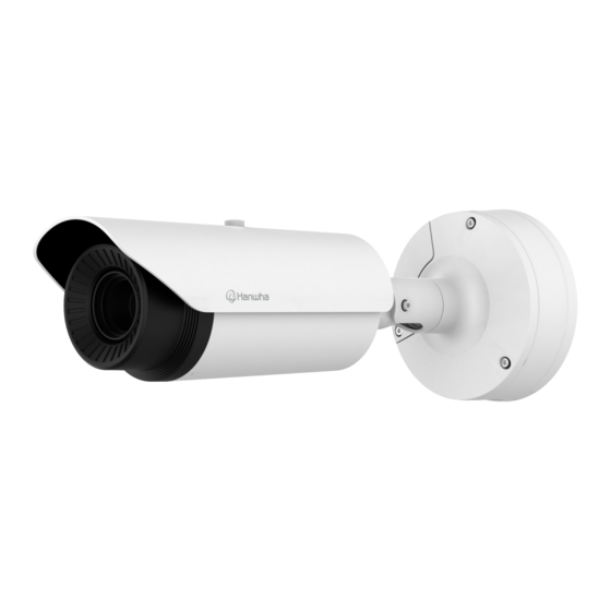
- Page 1 THERMAL NETWORK CAMERA User Manual TNO-4030T/TNO-4040T/TNO-4041T TNO-4050T/TNO-4051T TNO-4030TR/TNO-4040TR/TNO-4041TR TNO-L4030T/TNO-L4030TR TNO-L4040T/TNO-L4040TR/TNO-L4050T...
- Page 2 Thermal Network Camera User Manual Copyright ©2022 Co., Ltd. All rights reserved. Hanwha Vision Trademark Each of trademarks herein is registered. The name of this product and other trademarks mentioned in this manual are the registered trademark of their respective company. Restriction Copyright of this document is reserved.
- Page 3 overview IMPORTANT SAFETY INSTRUCTIONS WARNING TO REDUCE THE RISK OF FIRE OR ELECTRIC SHOCK, DO NOT EXPOSE THIS PRODUCT 1. Read these instructions. TO RAIN OR MOISTURE. DO NOT INSERT ANY METALLIC OBJECT THROUGH THE VENTILATION GRILLS OR OTHER OPENINGS ON THE EQUIPMENT. 2.
- Page 4 overview Class construction Please read the following recommended safety precautions carefully. An apparatus with CLASS construction shall be connected to a MAINS socket outlet with a ~ Do not place this apparatus on an uneven surface. protective earthing connection. ~ Do not install on a surface where it is exposed to direct sunlight, near heating equipment or heavy cold area.
-
Page 5: Table Of Contents
Memory Card Specifications NAS recommended specs What’s Included (TNO-4030T/4040T/4050T/ 4030TR/4040TR/L4030T/L4030TR/L4040T/ L4040TR/L4050T) What’s Included (TNO- APPENDIX Troubleshooting 4041T/4051T/4041TR) At a Glance (TNO-4030T/4040T/4050T/ 4030TR/4040TR/L4030T/L4030TR /L4040T/ L4040TR/L4050T) At a Glance (TNO-4041T/4051T/4041TR) INSTALLATION & CONNECTION Installation (TNO-4030T/4040T/4050T/ 4030TR/4040TR/L4030T/L4030TR/L4040T/ L4040TR/L4050T) Installation (TNO-4041T/4051T/4041TR) Inserting/Removing a Micro SD Memory... -
Page 6: Overview
overview RECOMMENDED PC SPECIFICATIONS NAS RECOMMENDED SPECS ~ CPU : Intel(R) Core(TM) i7 3.4 GHz or higher ~ Recommended capacity : 200GB or higher is recommended. ~ RAM : 8G or higher ~ For this camera, you are recommended to use a NAS with the following manufacturer’s specs. Recommended products : QNAP NAS, Synology NAS ~ Recommended browser: Chrome ~ Supported browsers: Chrome, Safari, Firefox, MS Edge(chromium based) -
Page 7: What's Included (Tno-4030T/4040T/4050T/4030Tr/4040Tr/L4030T/ L4030Tr/L4040T/L4040Tr/L4050T)
WHAT’S INCLUDED (TNO-4030T/4040T/4050T/4030TR/4040TR/L4030T/ Appearance Item Name Quantity Description L4030TR/L4040T/L4040TR/L4050T) Tapping Screw Used for installation on the wall or ceiling Please check if your camera and accessories are all included in the product package. (As for each sales country, accessories are not the same.) - Page 8 overview WHAT’S INCLUDED (TNO-4041T/4051T/4041TR) Appearance Item Name Quantity Description Please check if your camera and accessories are all included in the product package. (As for each sales country, accessories are not the same.) Sunshield Hold It fixes the sunshield with the camera. Appearance Item Name Quantity...
-
Page 9: At A Glance (Tno-4030T/4040T/4050T/4030Tr/4040Tr/L4030T/L4030Tr /L4040T/L4040Tr/L4050T)
AT A GLANCE (TNO-4030T/4040T/4050T/4030TR/4040TR/L4030T/L4030TR AT A GLANCE (TNO-4041T/4051T/4041TR) /L4040T/L4040TR/L4050T) Appearance & Components Appearance & Components Item Description Item Description Network Port Used to connect the PoE or Ethernet cable for network connection. Audio and alarm cable port Port to connect audio and alarm cables. -
Page 10: Installation & Connection
& connection installation & connection INSTALLATION (TNO-4030T/4040T/4050T/4030TR/4040TR/L4030T/L4030TR/ 6. Adjust the camera direction using the L wrench provided. L4040T/L4040TR/L4050T) When you adjust the camera position using a bracket, please loosen the bracket screw, adjust the camera, and tighten it. If you attempt to adjust it This camera is waterproof and in compliance with the IP66 spec, but the jack connected to the external cable is not. - Page 11 4. Insert the LAN cable into the large hole made by removing the Outdoor installation projected part of the rubber plug in step 1 above. When you install it outside of the building, please waterproof it with waterproof butyl rubber tape (can be 5.
- Page 12 installation & connection Installation Connecting waterproof power cable and LAN cable 1. Use the star-shaped wrench to separate the 1. Pick off the extruded part of the rubber cover on PT bracket from the main body. the bottom side of the bottom cover as shown in the figure below.
-
Page 13: Inserting/Removing A Micro Sd Memory
When it rains or the humidity is high, insertion or ejection of a Micro SD card is not recommended. Inserting a Micro SD Memory Card Insert a Micro SD card in the arrow direction shown in the figure. <TNO-4030T/4040T/4050T/4030TR/4040TR/L4030T/L4030TR/L4040T/L4040TR/L4050T> <TNO-4030T/4040T/4050T/4030TR/4040TR/L4030T/L4030TR/L4040T/L4040TR/L4050T> <TNO-4041T/4051T/4041TR>... -
Page 14: Connecting With Other Device
CONNECTING WITH OTHER DEVICE Ethernet Connection Connect the Ethernet cable to the local network or to the Internet. Monitor to install Connecting Wi-Fi (TNO-4030T/4040T/4050T/4030TR/4040TR/L4030T/L4030TR/ L4040T/L4040TR/L4050T) Ethernet Camera Setup 1. Connect OTG adapter (5-pin) and WiFi dongle to the micro USB terminal. - Page 15 Power Supply Connecting to Audio Input/Output Use the screwdriver to connect each line (+, –) of the power cable to the corresponding power port of the camera. Speaker When supplying PoE and DC 12V or PoE and AC 24V power at the same time, the equipment is powered by the external source (AC 24V, DC 12V).
- Page 16 installation & connection Connecting to the I/O port box RS-485 setup (TNO-4041T/4051T/4041TR) Connect the Alarm I/O cable to the corresponding port of the port box. All these operations above mentioned will be enabled only if the network camera is properly connected to the pan/tilt-compliant receiver.
- Page 17 To connect the external sensor Connect one strand of each signal line (2-strand) of the sensors to the [ALARM IN] port, and connect the other strand to the [GND] port. Alarm In Wiring Diagram External Inside of the camera VCC_3.3V connection RESISTOR RESISTOR...
-
Page 18: Network Connection And Setup
network connection and setup network connection and setup You can set up the network settings according to your network configurations. CONNECTING THE CAMERA DIRECTLY TO A DHCP BASED DSL/CABLE MODEM CONNECTING THE CAMERA DIRECTLY TO LOCAL AREA NETWORKING Connecting to the camera from a local PC in the LAN INTERNET 1. -
Page 19: Using Device Manager
If using a Broadband Router ~ IP Address : Enter an address falling in the IP range provided by the Broadband Router. Device manager program can be downloaded from <Support>-<Online Tool> menu at Hanwha Vision website ex) 192.168.1.2~254, 192.168.0.2~254, (https://www.HanwhaVision.com). -
Page 20: Manually Registering Camera
network connection and setup Configuring Dynamic IP AUTOMATICALLY CONFIGURING IP Receive IP address from DHCP 1. Click the camera from the list that you want to automatically ~ Example of the Dynamic IP environment configure the IP. TNO-L4030T - If a Broadband Router, with cameras connected, is assigned an IP address by the DHCP server 2. -
Page 21: Port Range Forward (Port Mapping) Setup
PORT RANGE FORWARD (PORT MAPPING) SETUP Setting up Port Range Forward for several network cameras ~ You can set a rule of Port Forwarding on the Broadband Router device through its configuration web page. If you have installed a Broadband Router with a camera connected, you must set the port range forwarding on the ~ A user can change each port using the camera setting screen. -
Page 22: Connecting To The Camera From A Shared Local Pc
network connection and setup CONNECTING TO THE CAMERA FROM A SHARED LOCAL PC 1. Run device manager. It will scan for connected cameras and display them as a list. 2. Double-click a camera to access. The Internet browser starts and connects to the camera. Access to the camera can also be gained by typing the camera’s IP address in the address bar of the Internet browser. -
Page 23: Connecting To The Camera
web viewer CONNECTING TO THE CAMERA PASSWORD SETTING When you access the product for the first time, you must register the Normally, you would login password. 1. Launch the Internet browser. For a new password with 8 to 9 digits, you must use at least 3 of 2. -
Page 24: Troubleshooting
appendix appendix TROUBLESHOOTING PROBLEM SOLUTION Voice is not recorded even though PROBLEM SOLUTION ~ You must enable the <Audio In> check box in <Basic> - <Video Profile>. audio input settings are configured. When an Windows 10 user accesses ~ This is what happens when microphone driver has been set to Realtek driver. ~ Verify the settings in the following sequence: the web viewer through Chrome <Motion detection>... - Page 25 Operation of this equipment in a residential area is likely to cause harmful interference in which case the user will be required to correct the interference at his own expense. Hanwha Vision cares for the environment at all product manufacturing stages, and is taking measures to provide customers with more environmentally friendly products.
Need help?
Do you have a question about the TNO-4030T and is the answer not in the manual?
Questions and answers