
Related Manuals for Gaggenau AI 540-120


Summary of Contents for Gaggenau AI 540-120
- Page 1 Operating and assembly instructions AI 540-120 AI 541-120 AI 542-120 AI 543-120 Freely Suspended Insular Hood...
-
Page 3: Table Of Contents
AI 541-120 AI 542-120 AI 543-120 Preface 1. Important notes Page 3-4 1.1 For your safety Page 3 1.2 Operating for the first time Page 4 1.3 About use Page 4 Features Page 5 3. Operation Page 6-8 4. Cleaning and care Page 9-10 5. -
Page 4: Preface
– a large number of control functions, – optimum illumination of the cooking surface by a dimmable halogen light. To ensure that you will be able to use this appli- ance in all its diversity, read through the operating and assembly instructions conscientiously... -
Page 5: Important Notes
– Adequate incoming air must be ensured if a – Hazardous or explosive substances and vapours wood, coal, gas or oil heater or an open hearth is must not be extracted! operated in the same room as the one in which –... -
Page 6: Operating For The First Time
– The appliance must be installed and connected – In the event of malfunctions, first of all check the by a specialist before it is operated for the first household fuses. If the problem has nothing to time. -
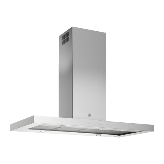
Page 7: Features
Ventilation duct 2 Control panel 3 Grease filters 4 Lighting Fig. 2 Installation accessories for exhaust air mode Stainless steel-design ventilation duct: LK 010-016 for ceiling heights of 2.23 - 2.41 m LK 010-026 for ceiling heights of 2.41 - 2.73 m LK 010-036 for ceiling heights of 2.73 - 2.99 m... -
Page 8: Operation
(see Fig. 4). When you briefly press the key, the lighting is increased up to the maximum level. You can dim the lighting to the required level by keeping the key pressed. Fig. 4 Fan levels Three fan speeds and one intensive speed are available (see Fig. - Page 9 Int key for the intensive level should be pressed when browning and frying in an open pan (see Fig. 6). If you have switched on the hood by selecting the intensive level, it will be switched off again automatically after 5 minutes.
-
Page 10: Operation
You can set the intensive level running time to 3, 5 or 10 minutes by simultaneously pressing the key and the 1, 2 or 3 key and you can store this setting (see Fig. 9). When delivered, the appliance is set to five minutes, i.e. the combination of the key and the key 2. -
Page 11: Cleaning And Care
Cleaning the grease filters The grease filter saturation display F flashes after an operating time of 30 hours to you indicate to you that you should clean the grease filter (see Fig. 3). The grease filters can of course be cleaned at any time, even if the grease filter saturation display has not started to flash. -
Page 12: Circulating Air Mode
Cleaning the extractor hood Clean the exterior of your extractor hood with a soft cloth and mild detergent solution. Do not use any strong, caustic or abrasive cleaning agents. Do not use any abrasive sponges or brushes either. Clean the stainless-steel extractor hood (AI 540/ AI 542) with stainless steel cleaner. -
Page 13: Maintenance
– Insert the lamp in the lampholder. Note: do not touch the halogen lamps with your hands. Use a cloth and touch the lamp only on its edges. – Engage the lamp cover. – Connect the appliance to the mains again. -
Page 14: Assembly Instructions
H 05 VV-F G 0,75. It is not allowed to pass the exhaust air into a flue The appliance must only be connected by an or exhaust air chimney that is in operation or into a authorised specialist. - Page 15 The dimensions above refer to a distance of 1.60 m – the pipes are not laid at an acute angle, but as from the floor to the bottom edge of the hood. bends and that they are inserted into the shaft at...
- Page 16 (max. 15 minutes). This will pose a risk of burns The extractor hood can only be used in exhaust air when touching the hot appliance exterior or parts of mode.
- Page 17 Using the drilling template mark the position of the screws on the ceiling. 2. Drill 4 holes Ø 8 mm for the wall plugs. Push the plugs flush with the ceiling (Fig. 19). Turn two screws to a 10 mm gap. Both screws...
- Page 18 (Fig. 22 and 23). Cut the flexible air pipe to the required length and fix it to the extractor hood. 6. Remove the cover plate from the rear of the support frame (Fig.
- Page 19 7. Slide the extractor hood into the on the side of the support frame (Note: take care not to trap the mains connecting cable) and immediately secure the hood with 4 screws (Fig. 25). 8. Screw the cover plate back on the rear of the support frame.
- Page 20 GAGGENAU HAUSGERÄTE GMBH CARL-WERY-STR. 34 · D - 81739 MÜNCHEN (0 89) 45 90 - 03 FAX (0 89) 45 90 - 23 47 www.gaggenau.com...
Need help?
Do you have a question about the AI 540-120 and is the answer not in the manual?
Questions and answers