
Related Manuals for Clarke weld MIG103NG


Summary of Contents for Clarke weld MIG103NG
- Page 1 NO GAS MIG WELDER MODEL NO: MIG103NG PART NO: 6015615 OPERATION & MAINTENANCE INSTRUCTIONS ORIGINAL INSTRUCTIONS GC06/23...
-
Page 2: Mig Welding Principles
When using the welder outside, you may need to erect a wind break. GUARANTEE This CLARKE product is guaranteed against faulty manufacture for a period of 12 months from the date of purchase. Please keep your receipt as proof of purchase. -
Page 3: General Precautions
SAFETY PRECAUTIONS FOR ALL TYPES OF WELDING WARNING: AS WITH ALL MACHINERY, THERE ARE CERTAIN HAZARDS INVOLVED WITH THEIR OPERATION AND USE. EXERCISING RESPECT AND CAUTION WILL CONSIDERABLY LESSEN THE RISK OF PERSONAL INJURY. HOWEVER, IF NORMAL SAFETY PRECAUTIONS ARE OVERLOOKED, OR IGNORED, PERSONAL INJURY TO THE OPERATOR MAY RESULT. - Page 4 perchloroethylene vapours to form phosgene. DO NOT WELD or cut where solvent vapours can be drawn into the welding or cutting atmosphere or where the radiant energy can penetrate to atmospheres containing even minute amounts of trichloroethylene or perchloroethylene. C) FIRE AND EXPLOSION PREVENTION Causes of fire and explosion are: 1.
- Page 5 A container with unknown contents should be cleaned (see paragraph above). DO NOT depend on sense of smell or sight to determine if it is safe to weld or cut. Hollow castings or containers must be vented before welding or cutting as they can explode.
-
Page 6: Toxic Fume Prevention
leave a permanent dark area in the field of vision. Before welding whilst wearing contact lenses, seek advice from your optician. PROTECTION OF NEARBY PERSONNEL For production welding, a separate, well vented room or enclosed bay is best. In open areas, surround the operation with low reflective, non- combustible screens or panels. - Page 7 Examples of conducting objects include, but are not limited to, buildings, electrical tools, work benches, welding power source cases, workpieces, etc. Never touch the electrode and any metal object unless the welding power source is off. When installing, connect the frames of each unit such as welding power source, control, work table, and water circulator to the building earth.
-
Page 8: Preparation Of The Working Area
9. NEVER use or store in a damp environment. DO NOT EXPOSE TO RAIN. 10. NEVER attempt any electrical or mechanical repair unless your are a qualified technician. If you have a problem with the machine contact your local CLARKE dealer. Parts & Service: 020 8988 7400 / E-mail: Parts@clarkeinternational.com or Service@clarkeinternational.com... - Page 9 16. NEVER allow the earth cable or torch hose to become wrapped around the operator or any person in the vicinity. A comprehensive range of CLARKE safety equipment for use when welding, is available from your local dealer. Consideration should be given to shielding the supply cable of permanently installed welding equipment, in metallic conduit or equivalent.
-
Page 10: Electrical Connections
ELECTRICAL CONNECTIONS WARNING: READ THESE ELECTRICAL SAFETY INSTRUCTIONS FULLY BEFORE CONNECTING THE PRODUCT TO THE MAINS SUPPLY. This product is provided with a standard 13 amp, 230 volt (50Hz), BS 1363 plug, for connection to a standard, domestic electrical supply. Should the plug need changing, make sure that a plug of identical specification is used. -
Page 11: Safety Symbols
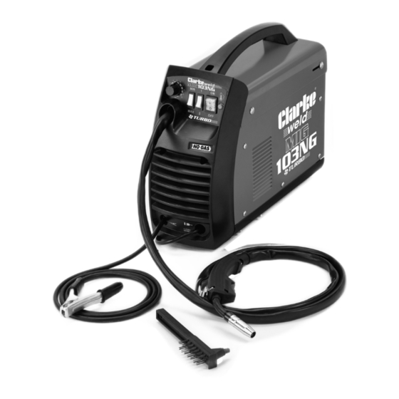
SAFETY SYMBOLS General Warning. This indicates that failing to follow these instructions could result in injury or damage to the machine. Recycle unwanted materials instead of disposing of them as waste. All tools, accessories and packaging should be sorted, taken to a recycling centre and disposed of in a manner which is compatible with the environment. - Page 12 OVERVIEW NO DESCRIPTION NO DESCRIPTION Headshield Assembly Hammer/Brush Tool Control Panel Torch Earth Clamp Torch Hose INVENTORY The items supplied include the following: • 1 x Gasless MIG Welder (torch and earth clamp attached) • 2 x 0.9 mm Torch Tips (one installed in the torch) •...
-
Page 13: The Control Panel
THE CONTROL PANEL 1. Thermal overload light. If the duty cycle is exceeded due to welding too long with a high current, the amber overload light will illuminate and the welder will turn off. When it has cooled down (approx. 5 to 10 minutes), the light will go out, the power will be restored and welding can continue. -
Page 14: Assembling The Welding Shield
• The clear glass panel should be replaced when it becomes badly pitted. 4. When replacing the glass panels, only use parts supplied by Clarke International. The dark panel is a certified, optical glass and should not be exchanged for any other type. -
Page 15: Preparation For Use
MOUNTING THE WELDING WIRE SPOOL Warning: Ensure that the welder is not connected to the mains supply. NOTE: Spools of welding wire are available from your Clarke dealer. 1. Open the side panel, by pushing the latch down and allowing the side panel to drop down. -
Page 16: Threading The Wire
5. Pull the roller off the drive spindle. • The groove size is stamped on the corresponding side of the roller. Select the groove size according to the size of the wire you are using and put the roller back on the spindle with your chosen side facing you. - Page 17 6. Lower the cover and slide it forward to close. 7. Pull off the torch shroud with a twisting movement, then unscrew the contact tip. 8. Connect the welder to the power supply and switch ON. 9. Set the ‘WIRE FEED’ rotary control on the front panel to position 7 or 8 and squeeze the trigger on the torch body.
-
Page 18: Operating The Welder
OPERATING THE WELDER PREPARING THE WORKPIECE The area being welded should be perfectly clean. Any coating, plating or corrosion must be removed, otherwise a good weld will be impossible. Attach the earth clamp to the workpiece as close to the point of weld as possible without it being intrusive. -
Page 19: Thermal Overload
NOTE: Listen to the sound made. An irregular crackling sound denotes too high a wire speed. Decrease the speed until a regular, strong buzzing sound is heard. THERMAL OVERLOAD The ‘Thermal Overload’ shuts off the welder when it becomes too hot, due to the duty cycle being exceeded. -
Page 20: Maintenance
Check the hose for security and damage. As a general rule the power supply should be inspected at least annually. Consult your CLARKE dealer for advice if necessary. Wire feed unit: The feed roller wire guide plays an important part in obtaining consistent results. -
Page 21: Troubleshooting
TROUBLESHOOTING Your CLARKE MIG Welder has been designed to give long and trouble free service. If however, having followed the instructions in this booklet carefully you still encounter problems, the following points should help identify and resolve them. PROBLEM CAUSE... - Page 22 If you have any problems which cannot be resolved by reference to the above, or if you require spare parts for your welder please contact your local Clarke dealer. Parts & Service: 020 8988 7400 / E-mail: Parts@clarkeinternational.com or Service@clarkeinternational.com...
-
Page 23: The Rating Plate
THE RATING PLATE Name and address of Time taken from cold status manufacturer welding to overheating Model number, part number Rated Welding Current symbol Batch number Load Voltage symbol Single phase transformer-rectifier Energy Input symbol British Standards applied Rated supply voltage Welding process Rated maximum supply current Welding Current symbol... -
Page 24: Specifications
Spool capacity Feed speed range 3M/min Welding capacity (steel) CLARKE International reserve the right to change specifications at any time without prior notice DUTY CYCLE The duty cycle determines the machine ‘down time’. i.e 10% means 1 minutes operation followed by 9 minutes of rest. The duty cycle must be adhered to... -
Page 25: Arc Activated Headshields
CONSUMABLES The following are some of the accessories available from your CLARKE dealer. Please quote the part numbers shown below: Part Description Part Comment number Welding Wire Flux cored mild steel (mini 8132110 Use for no gas welding Spools spool) 0.9mm Stainless Steel 0.8mm (mini... -
Page 26: Component Parts
COMPONENT PARTS Operating knob Top cover Selector switch Left side plate Power switch Handle Indicator Axle Welding torch Wire feeder Earth clamp & cable Wire spool Power cable Middle panel Transformer Cooling fan Front plastic cover Rear panel 10 Top plastic cover Main transformer 11 Control PCB Thermal cut-out... -
Page 27: Declarations Of Conformity
DECLARATIONS OF CONFORMITY Parts & Service: 020 8988 7400 / E-mail: Parts@clarkeinternational.com or Service@clarkeinternational.com...
Need help?
Do you have a question about the weld MIG103NG and is the answer not in the manual?
Questions and answers