Table of Contents
Advertisement
Quick Links
Advertisement
Table of Contents

Related Manuals for Gaggenau AH600190


Summary of Contents for Gaggenau AH600190
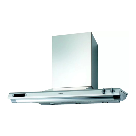
- Page 1 Operating and assembly instructions AH 600-190 Extractor hood...
-
Page 2: Table Of Contents
AH 600-190 Preface 1. Important notes Page 3-4 1.1 For your safety Page 3 1.2 Operating for the first time Page 4 1.3 About use Page 4 2. Structure and operating principle Page 5-6 2.1 Structure of the appliance Page 5 2.2 Accessories/special accessories... -
Page 3: Preface
– effective extraction thanks to the so-called “Coanda effect” – low operating noise To ensure that you will be able to use this appli- ance in all its diversity, read through the operating and assembly instructions conscientiously before operating it for the first time. The instructions contain important notes on use, installation and maintenance of the appliance. -
Page 4: Important Notes
– Never operate the appliance without a grease filter. – Adequate incoming air must be ensured if a wood, coal, gas or oil heater or an open hearth is – Hazardous or explosive substances and operated in the same room as the one in which vapours must not be extracted! the hood is installed. -
Page 5: Operating For The First Time
1.2 Operating for the first time 1.3 About use – The appliance is intended solely for use in the Before operating the appliance for the first time, household and must not be put to any other uses. please pay attention to the following notes: –... -
Page 6: Structure And Operating Principle
Installation accessories: – Activated charcoal filter: KF 600-090 Exhaust air: – Back draught flap RK 040-150: Back draught Ventilation duct for ceiling heights of 2.27 - 2.60 m: flap for insertion in the extractor’s blow-out LK 600-010 opening Ventilation duct for ceiling heights of 2.61 - 3.00 m: –... -
Page 7: Operating Principle
The grease filter intercepts and traps the grease and odour particles in the air. In the exhaust air mode: The fan in the extractor hood sucks in the kitchen vapours and passes them through the grease filter Fig. 4 to outdoors. -
Page 8: Operation
Switching off – Turn the “Ventilation level” control knob to the 0 position (Fig. 8). – The set level 0 is displayed for a few seconds. Note: The light can be switched on and off at any time. To do this, turn the “Light” control knob to the (Light) position. -
Page 9: Special Functions
You should select the intensive level when browning and frying in an open pan. Switching on: (Fig. 10) – Turn the control knob to a ventilation level (1-3). – Press the intensive level key. The intensive level symbol appears on the display. The previously selected ventilation level flashes on the display. -
Page 10: Cleaning And Care
Proceed as follows: – Grip the grease filter handles and press the slide towards the rear. – Pull the grease filter out of its mount in the downward direction (Fig. 13). – Repeat the operation with the other grease filters. - Page 11 Activated charcoal filters do not contain any polluting substances. Old activated charcoal filters can be disposed of as domestic waste. If used once daily, the activated charcoal filter must be replaced approximately once to twice every year. First remove the grease filter.
-
Page 12: Maintenance
– Remove the screws on the lamp cover. The lamp cover tilts down and cannot be removed from the appliance (Fig. 15). – Turn the lamp to the left and remove the lamp (Fig. 16). Fig. 16 Defective lamps must only be replaced by lamps of the same type (Cool Beam)! You can obtain the original spare part (No. -
Page 13: Assembly Instructions
2 screws). It is not allowed to pass the exhaust air into a flue The appliance must only be connected by an or exhaust air chimney that is in operation or into a authorised specialist. - Page 14 The dimensions above refer to a distance of 1.60 m – the pipes are not laid at an acute angle, but as from the floor to the bottom edge of the hood. bends and that they are inserted into the shaft at...
- Page 15 Important: Before marking the securing holes, make sure that no electricity or water lines or other lines are laid at the drilling points in the wall. Exhaust air operation: – From the bottom edge of the hood, mark a center line on the wall.
- Page 16 – Secure the hood to the wall using the 4 screws b with shims c (Fig. 20). – Establish the pipe connection. – Establish the electrical connection. – Extract the protective file from the chimney paneling. Note: Avoid damaging the sensitive stainless steel surfaces.
- Page 17 (Figure 19). – Secure the hood to the wall using the 4 screws b with shims c. – Screw the retaining bracket for the chimney...
- Page 18 – Join the chimney shoe with the chimney base using the 6 screws (3.5 x 9.5 mm) (Fig. 26). – Fit the top of the chimney into the base. Make sure that the fastening holes on the side are at the top.
Need help?
Do you have a question about the AH600190 and is the answer not in the manual?
Questions and answers