Table of Contents
Advertisement
Advertisement
Table of Contents

Subscribe to Our Youtube Channel
Related Manuals for Gaggenau AH 600


Summary of Contents for Gaggenau AH 600
- Page 1 Operating and assembly instructions AH 600-790 Extractor hood...
-
Page 2: Table Of Contents
AH 600-790 Preface Safety notes Page 3 1. Important notes Page 4-5 1.1 For your safety Page 4 1.2 Operating for the first time Page 5 1.3 About use Page 5 2. Structure and operating principle Page 6-7 2.1 Structure of the appliance Page 6 2.2 Accessories/special accessories... -
Page 3: Preface
Preface With your new extractor hood, working in the kitchen will be even more fun. The appliance offers you a number of advantages: – effective extraction thanks to the so-called “Coanda effect” – low operating noise To ensure that you will be able to use this appli- ance in all its diversity, read through the operating and assembly instructions conscientiously before operating it for the first time. -
Page 4: Safety Notes
Safety notes Read And Save These Instructions. WARNING - TO REDUCE THE RISK OF FIRE, WARNING - TO REDUCE THE RISK OF INJURY ELECTRIC SHOCK, OR INJURY TO PERSONS, TO PERSONS IN THE EVENT OF A RANGE OBSERVE THE FOLLOWING: TOP GREASE FIRE, OBSERVE THE FOLLOWING: a.) Use this unit only in the manner intended by the... -
Page 5: Important Notes
1. Important notes 1.1 For your safety – Damaged appliances must not be operated. – Isolate the appliance from the mains during every maintenance operation. To do this, – The appliance must only be connected by an actuate the corresponding fuse. authorised specialist, paying attention to the relevant regulations of the power supply –... -
Page 6: Operating For The First Time
Gaggenau after- – The rating plate for this appliance is included sales service. with the instructions on a separate sheet. Store the rating plate in the same location as your operating and assembly instructions. -
Page 7: Structure And Operating Principle
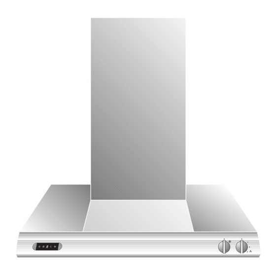
2. Structure and operating principle 2.1 Structure of the appliance 1 Display 2 Glass plates 3 Air duct 4 Control panel Fig. 2 5 Grease filter key 6 Ventilation level display 7 “Coanda level” key 8 “Light” control knob 9 “Ventilation level” control knob 10 “After-running”... -
Page 8: Operating Principle
2.3 Operating principle This extractor hood swiftly and silently extracts all odours produced while cooking. You can set different intensity levels depending on the intensity of odours. The exhaust air first passes through the integrated grease filter. The grease filter intercepts and traps the grease and odour particles in the air. -
Page 9: Operation
3. Operation 3.1 Switching on and off Switching on – Turn the “Ventilation level” control knob to the ventilation level you require (Fig. 7). – The set level is displayed. Fig. 7 Switching off – Turn the “Ventilation level” control knob to the 0 position (Fig. -
Page 10: Special Functions
3.2 Special functions Intensive level You should select the intensive level when browning and frying in an open pan. Switching on: (Fig. 10) – Turn the control knob to a ventilation level (1-3). – Press the intensive level key. The intensive level symbol appears on the display. -
Page 11: Cleaning And Care
4. Cleaning and care Cleaning the grease filters: (Grease filter saturation) symbol flashes on the display after an operating time of 30 hours. Flashing of this symbol signals to you that the grease filters have to be cleaned. The grease filters can be cleaned at any time, even if the (grease filter saturation) symbol does not flash. - Page 12 Air recirculation If, when purchasing the extractor hood, you have decided in favour of the air recirculation mode, the activated charcoal filter KF 600-090 must be replaced after a certain amount of hood operation. Note: The activated charcoal filter is not included in the scope of delivery of the hood.
-
Page 13: Maintenance
If the power supply is functioning correctly, but your appliance still does not work, please contact your Gaggenau dealer who will provide you with the address and telephone number of your nearest manufacturer’s authorized service agent or contact Gaggenau USA on (800) 828-9165. -
Page 14: Assembly Instructions
It must be possible to isolate all poles of the appliance from the mains by way of the domestic fuse, or by means of accessible isolating device with a contact gap of at least 3 mm. AH 600-790 FD xxxx xxxx AC 120V... -
Page 15: Installation
6.2 Installation The applicable regulations of the energy supply companies and the regional construction WARNING - TO REDUCE THE RISK OF FIRE, regulations must be observed when installing ELECTRIC SHOCK, OR INJURY TO PERSONS, the hood. OBSERVE THE FOLLOWING: The minimum distance from the worktop to the a.) Installation work and electrical wiring must be bottom edge of the wall hood is for electrical done by qualified person(s) in accordance with... - Page 16 Flexible aluminium pipes, corrosion-protected Exhaust air operation sheet metal pipes and exhaust air pipes whose Depending on the ceiling height, the following duct material conforms to fire B1 in accordance with units are at your disposal for exhaust air operation: DIN 4102 can be used.
- Page 17 Proceed as follows: 15 ( ") Important: Before marking the securing holes, make sure that no electricity or water lines or other lines are laid at the drilling points in the wall. ") Exhaust air operation: – From the bottom edge of the hood, mark a center ") line on the wall.
- Page 18 – Secure the hood to the wall using the 4 screws b with shims c (Fig. 20). – Establish the pipe connection. – Establish the electrical connection. – Extract the protective file from the chimney paneling. Note: Avoid damaging the sensitive stainless steel surfaces.
- Page 19 Recirculation air operation – From the bottom edge of the hood, mark a center line on the wall. 15 ( ") – With the aid of the drilling template, mark the positions of the screws on the wall. Mark the contour of the hook-in area.
- Page 20 – Screw together the air guidance housing and screw it onto the two retaining brackets (Fig. 25). – Establish the pipe connection between the air connection piece and the air guidance housing. – Establish the electrical connection. – Stick the included sealing strips (8 strips) around the air slots on the top chimney paneling.
Need help?
Do you have a question about the AH 600 and is the answer not in the manual?
Questions and answers