Table of Contents
Advertisement
Quick Links
YASKAWA AC Drive
Fan Replacement Procedure
Drive Model
CIPR-GA70xxxxxxxxx, CIPR-GA80xxxxxxxxx
CIPR-CH70xxxxxxxxx, CIPR-CR70xxxxxxxxx
CIPR-LA70xxxxxxxxx
To properly use the product, read this manual.
安川インバータ
ファン交換要領書
CIPR-GA70xxxxxxxxx, CIPR-GA80xxxxxxxxx
インバータ形式
CIPR-CH70xxxxxxxxx, CIPR-CR70xxxxxxxxx
CIPR-LA70xxxxxxxxx
製品を安全にお使いいただくために,この取扱説明書を必ずお読みください。
MANUAL NO. TOBP C730600 99B
Advertisement
Chapters
Table of Contents

Related Manuals for YASKAWA CIPR-GA70 Series


Summary of Contents for YASKAWA CIPR-GA70 Series
- Page 1 YASKAWA AC Drive Fan Replacement Procedure Drive Model CIPR-GA70xxxxxxxxx, CIPR-GA80xxxxxxxxx CIPR-CH70xxxxxxxxx, CIPR-CR70xxxxxxxxx CIPR-LA70xxxxxxxxx To properly use the product, read this manual. 安川インバータ ファン交換要領書 CIPR-GA70xxxxxxxxx, CIPR-GA80xxxxxxxxx インバータ形式 CIPR-CH70xxxxxxxxx, CIPR-CR70xxxxxxxxx CIPR-LA70xxxxxxxxx 製品を安全にお使いいただくために,この取扱説明書を必ずお読みください。 MANUAL NO. TOBP C730600 99B...
- Page 2 This Page Intentionally Blank YASKAWA TOEP C730600 99B Fan Replacement Procedure...
-
Page 3: Table Of Contents
Circuit Board Cooling Fan Installation ........51 YASKAWA TOEP C730600 99B Fan Replacement Procedure... - Page 4 Revision History ............64 YASKAWA TOEP C730600 99B Fan Replacement Procedure...
-
Page 5: Overview
1 Overview Overview This manual shows you how to replace the cooling fans on Yaskawa drives. Explanation of Signal Words WARNING Read and understand this manual before you install, operate, or do maintenance on the drive. Install the drive as specified by this manual and local codes. The symbols in this section identify safety messages in this manual. -
Page 6: Drive Models And Number Of Fans
Procedure 4007 4007 4006 Procedure 4009 4009 4007 Procedure 4012 4012 4009 4012 Procedure 4018 4018 4015 4019 Procedure 4023 4023 4018 4023 Procedure 4031 4031 4024 4030 Procedure 4038 4038 4031 4039 YASKAWA TOEP C730600 99B Fan Replacement Procedure... - Page 7 Procedure 4453 4414 T477 4568 Procedure 4568 4453 T568 4605 Procedure 4675 4605 T605 4720 Procedure T720 4810 4810 Procedure I 4930 4930 Procedure I 4H11 4H11 Procedure I 4H12 4H12 Procedure I YASKAWA TOEP C730600 99B Fan Replacement Procedure...
-
Page 8: Replace Cooling Fans And Circulation Fans
To remove the fan finger guard from the drive, push the hooks on the left and right sides of it and pull up. A - Fan finger guard Figure 5.1 Remove the Fan Finger Guard YASKAWA TOEP C730600 99B Fan Replacement Procedure... -
Page 9: Fan Installation
A - Cooling fan Figure 5.2 Remove the Cooling Fan ■ Fan Installation Reverse the removal procedure for fan installation. Connect the relay connector between the drive and cooling fan. Figure 5.3 Connect the Relay Connector YASKAWA TOEP C730600 99B Fan Replacement Procedure... - Page 10 Figure 5.5 Put the Cable and Connector in the Drive Recess Make sure that the cable and connector are in the correct space. Insert the fan finger guard straight until the hooks click into place. Figure 5.6 Reattach the Fan Finger Guard YASKAWA TOEP C730600 99B Fan Replacement Procedure...
-
Page 11: Fan Replacement (Procedure B)
Figure 5.7 Remove the Fan Finger Guard Pull the cooling fans straight up from the drive. Disconnect the relay connectors and remove the fans from the drive. A - Cooling fans Figure 5.8 Remove the Cooling Fans YASKAWA TOEP C730600 99B Fan Replacement Procedure... -
Page 12: Fan Installation
Align the notches on the fans with the pins on the drive and install the cooling fans in the drive. A - Notch on fan C - Front of drive B - Alignment pins on drive Figure 5.10 Install the Cooling Fans YASKAWA TOEP C730600 99B Fan Replacement Procedure... - Page 13 Hold the fan finger guard at an angle and put the connector tabs on the fan finger guard into the holes on the drive. A - Front of drive C - Connector tabs B - Drive holes Figure 5.12 Reattach the Fan Finger Guard YASKAWA TOEP C730600 99B Fan Replacement Procedure...
-
Page 14: Fan Replacement (Procedure C)
To remove the fan finger guard from the drive, push the hooks on the left and right sides of it and pull up. A - Fan finger guard Figure 5.14 Remove the Fan Finger Guard YASKAWA TOEP C730600 99B Fan Replacement Procedure... -
Page 15: Fan Installation
A - Cooling fans Figure 5.15 Remove the Cooling Fans ■ Fan Installation Reverse the removal procedure for fan installation. Connect the relay connectors between the drive and cooling fans. Figure 5.16 Connect the Relay Connectors YASKAWA TOEP C730600 99B Fan Replacement Procedure... - Page 16 A - Front of drive B - Space for cables Figure 5.18 Put the Cables and Connectors in the Drive Recess Make sure that the cables and connectors are in the correct space. YASKAWA TOEP C730600 99B Fan Replacement Procedure...
-
Page 17: Fan Replacement (Procedure D)
To remove the fan finger guard from the drive, push the hooks on the left and right sides of it and pull up. A - Fan finger guard Figure 5.20 Remove the Fan Finger Guard YASKAWA TOEP C730600 99B Fan Replacement Procedure... -
Page 18: Fan Installation
A - Cooling fans Figure 5.21 Remove the Cooling Fans ■ Fan Installation Reverse the removal procedure for fan installation. Connect the relay connectors between the drive and cooling fans. Figure 5.22 Connect the Relay Connectors YASKAWA TOEP C730600 99B Fan Replacement Procedure... - Page 19 A - Front of drive B - Space for cables Figure 5.24 Put the Cables and Connectors in the Drive Recess Make sure that the cables and connectors are in the correct space. YASKAWA TOEP C730600 99B Fan Replacement Procedure...
-
Page 20: Fan Replacement (Procedure E)
To remove the fan finger guard from the drive, push the tabs on the left and right sides of it and pull up the back side of the guard. A - Fan finger guard Figure 5.26 Remove the Fan Finger Guard YASKAWA TOEP C730600 99B Fan Replacement Procedure... -
Page 21: Fan Installation
A - Cooling fans Figure 5.27 Remove the Cooling Fans ■ Fan Installation Reverse the removal procedure for fan installation. Connect the relay connectors between the drive and cooling fans. Figure 5.28 Connect the Relay Connectors YASKAWA TOEP C730600 99B Fan Replacement Procedure... - Page 22 A - Front of drive B - Space for cables Figure 5.30 Put the Cables and Connectors in the Drive Recess Make sure that the cables and connectors are in the correct space. YASKAWA TOEP C730600 99B Fan Replacement Procedure...
-
Page 23: Fan Replacement (Procedure F)
Use the instructions in this manual to replace the cooling fans. When you do maintenance on the fans, replace all the fans to increase product life. If you install the fans incorrectly, it can cause damage to the drive. YASKAWA TOEP C730600 99B Fan Replacement Procedure... -
Page 24: Fan Removal
Note: The number of fans is different for different drive models. A - Cooling fans Figure 5.34 Remove the Cooling Fans ■ Fan Installation Reverse the removal procedure for fan installation. YASKAWA TOEP C730600 99B Fan Replacement Procedure... - Page 25 Align the notches on the fans with the pins on the drive and install the cooling fans in the drive. A - Notch on fan C - Front of drive B - Alignment pins on drive Figure 5.36 Install the Cooling Fans YASKAWA TOEP C730600 99B Fan Replacement Procedure...
- Page 26 When you install the cooling fans, make sure that you do not pinch cables between the fan finger guards and the drive. A - Front of drive C - Connector tab B - Insertion area Figure 5.38 Reattach the Fan Finger Guards YASKAWA TOEP C730600 99B Fan Replacement Procedure...
-
Page 27: Circulation Fan Removal
Remove the cable from the clamps. A - Fan unit C - Fan cable B - Clamps Figure 5.40 Remove the Fan Cable YASKAWA TOEP C730600 99B Fan Replacement Procedure... - Page 28 To remove the fan unit, it is only necessary to loosen the screws. A - Fan unit B - Screws Figure 5.41 Slide the Fan Unit Disconnect the relay connector and remove the fan unit. Figure 5.42 Remove the Fan Unit YASKAWA TOEP C730600 99B Fan Replacement Procedure...
-
Page 29: Circulation Fan Installation
Align the pin on the fan unit base with the notch on the fan and put the fan in the fan unit base, then use the screws to safety it. Tighten the screws to a correct tightening torque: • 0.98 N∙m to 1.33 N∙m (8.67 lbf∙in to 11.77 lbf∙in) YASKAWA TOEP C730600 99B Fan Replacement Procedure... - Page 30 Put the fan unit into the specified location and slide it to the left, then use screws to safety it to the drive. Tighten the screws to a correct tightening torque: • 0.98 N∙m to 1.33 N∙m (8.67 lbf∙in to 11.77 lbf∙in) YASKAWA TOEP C730600 99B Fan Replacement Procedure...
- Page 31 Figure 5.48 Safety the Fan Cable through the Clamps Install the drive cover. Energize the drive and set o4-03 = 0 [Fan Operation Time Setting = 0 h] to reset the fan operation time. YASKAWA TOEP C730600 99B Fan Replacement Procedure...
-
Page 32: Fan Replacement (Procedure G)
Loosen the screws that safety the fan unit and slide the slide panel to the left. Note: To remove the fan unit, it is only necessary to loosen the screws in position B. Remove the screws in position A. YASKAWA TOEP C730600 99B Fan Replacement Procedure... - Page 33 C - Slide panel B - Screw position B Figure 5.50 Slide the Slide Panel Remove the fan unit and the slide panel at the same time. Figure 5.51 Remove the Fan Unit YASKAWA TOEP C730600 99B Fan Replacement Procedure...
-
Page 34: Fan Installation
Align the pins on the fan unit base with the notches on the fans and put the fans in the fan unit base, then use the screws to safety them. Tighten the screws to a correct tightening torque: YASKAWA TOEP C730600 99B Fan Replacement Procedure... - Page 35 C - Alignment pin on fan unit base Figure 5.54 Install the Cooling Fans and Circulation Fan Put the cables and connectors in the recess of the drive. Note: Safety the relay cables to the hooks. YASKAWA TOEP C730600 99B Fan Replacement Procedure...
- Page 36 5 Replace Cooling Fans and Circulation Fans A - Cooling fans D - Relay cables B - Cable hooks E - Circulation fan C - Relay connectors Figure 5.55 Put the Cables and Connectors in the Drive Recess YASKAWA TOEP C730600 99B Fan Replacement Procedure...
- Page 37 Tighten the screws to a correct tightening torque: • Screws in Position A: 0.98 N∙m to 1.33 N∙m (8.67 lbf∙in to 11.77 lbf∙in) • Screws in Position B: 1.96 N∙m to 2.53 N∙m (17.35 lbf∙in to 22.39 lbf∙in) YASKAWA TOEP C730600 99B Fan Replacement Procedure...
- Page 38 B - Fan connectors Figure 5.58 Connect Cooling Fan Connectors Install the drive cover. Energize the drive and set o4-03 = 0 [Fan Operation Time Setting = 0 h] to reset the fan operation time. YASKAWA TOEP C730600 99B Fan Replacement Procedure...
-
Page 39: Circuit Board Cooling Fan Removal
Loosen the screws that safety the circuit board cooling fan unit and slide the circuit board cooling fan unit up. Note: To remove the fan unit, it is only necessary to loosen the screws. YASKAWA TOEP C730600 99B Fan Replacement Procedure... - Page 40 5 Replace Cooling Fans and Circulation Fans A - Screws Figure 5.60 Slide the Circuit Board Cooling Fan Units Remove the circuit board cooling fan units. Figure 5.61 Remove the Circuit Board Cooling Fan Units YASKAWA TOEP C730600 99B Fan Replacement Procedure...
-
Page 41: Circuit Board Cooling Fan Installation
Put the circuit board cooling fan unit into the specified location and slide it down, then use the screws to safety it to the drive. Tighten the screws to a correct tightening torque: • 0.98 N∙m to 1.33 N∙m (8.67 lbf∙in to 11.77 lbf∙in) YASKAWA TOEP C730600 99B Fan Replacement Procedure... - Page 42 B - Fan cable Figure 5.65 Fan Connect Cooling Fan Connectors Install the drive cover. Energize the drive and set o4-03 = 0 [Fan Operation Time Setting = 0 h] to reset the fan operation time. YASKAWA TOEP C730600 99B Fan Replacement Procedure...
-
Page 43: Fan Replacement (Procedure H)
Figure 5.66 Unplug the Fan Cables Loosen the screws that safety the fan unit. Note: To remove the fan unit, it is only necessary to loosen the screws in position B. Remove the screws in position A. YASKAWA TOEP C730600 99B Fan Replacement Procedure... - Page 44 5 Replace Cooling Fans and Circulation Fans A - Screw position A B - Screw position B Figure 5.67 Loosen the Screws Remove the fan unit. Figure 5.68 Remove the Fan Unit YASKAWA TOEP C730600 99B Fan Replacement Procedure...
-
Page 45: Fan Installation
Align the pins on the fan unit base with the notches on the fans and put the fans in the fan unit base, then use the screws to safety them. Tighten the screws to a correct tightening torque: • 0.98 N∙m to 1.33 N∙m (8.67 lbf∙in to 11.77 lbf∙in) YASKAWA TOEP C730600 99B Fan Replacement Procedure... - Page 46 C - Alignment pin on fan unit base Figure 5.71 Install the Cooling Fans and Circulation Fan Put the cables and connectors in the recess of the drive. Note: Safety the relay cables to the hooks. YASKAWA TOEP C730600 99B Fan Replacement Procedure...
- Page 47 Tighten the screws to a correct tightening torque: • Screws in Position A: 0.98 N∙m to 1.33 N∙m (8.67 lbf∙in to 11.77 lbf∙in) • Screws in Position B: 1.96 N∙m to 2.53 N∙m (17.35 lbf∙in to 22.39 lbf∙in) YASKAWA TOEP C730600 99B Fan Replacement Procedure...
- Page 48 Figure 5.73 Install the Fan Unit Connect the fan cable to the fan connectors. A - Fan unit C - Fan cable B - Fan connectors Figure 5.74 Connect Cooling Fan Connectors Install the drive cover. YASKAWA TOEP C730600 99B Fan Replacement Procedure...
-
Page 49: Circuit Board Cooling Fan Removal
Loosen the screws that safety the circuit board cooling fan unit and slide the circuit board cooling fan unit up. Note: To remove the fan unit, it is only necessary to loosen the screws. YASKAWA TOEP C730600 99B Fan Replacement Procedure... - Page 50 5 Replace Cooling Fans and Circulation Fans A - Screws Figure 5.76 Slide the Circuit Board Cooling Fan Unit Remove the circuit board cooling fan units. Figure 5.77 Remove the Circuit Board Cooling Fan Units YASKAWA TOEP C730600 99B Fan Replacement Procedure...
-
Page 51: Circuit Board Cooling Fan Installation
Put the circuit board cooling fan unit into the specified location and use screws to safety it to the drive. Tighten the screws to a correct tightening torque: • 0.98 N∙m to 1.33 N∙m (8.67 lbf∙in to 11.77 lbf∙in) YASKAWA TOEP C730600 99B Fan Replacement Procedure... - Page 52 B - Fan cables Figure 5.81 Connect the Fan Cables Install the drive cover. Energize the drive and set o4-03 = 0 [Fan Operation Time Setting = 0 h] to reset the fan operation time. YASKAWA TOEP C730600 99B Fan Replacement Procedure...
-
Page 53: Fan Replacement (Procedure I)
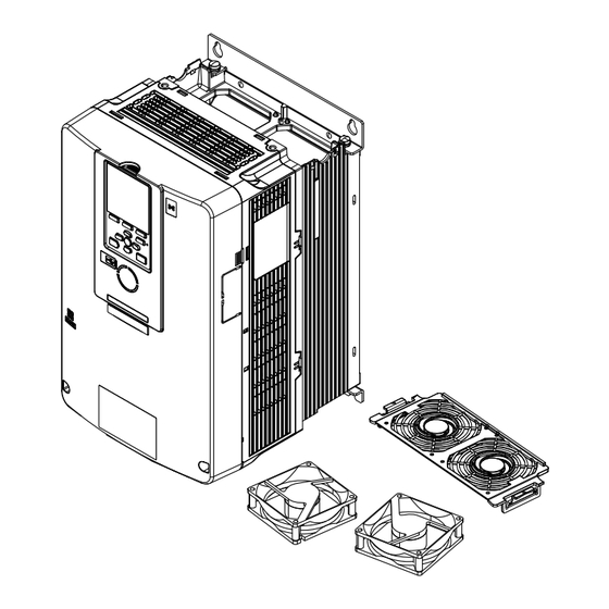
Unplug the fan cables from the fan connectors. A - Fan connectors B - Fan cables Figure 5.82 Components YASKAWA TOEP C730600 99B Fan Replacement Procedure... - Page 54 Loosen the screws that safety the fan unit. A - Screw position A B - Screw position B Figure 5.83 Loosen the Screws Remove the fan unit. Figure 5.84 Remove the Fan Unit YASKAWA TOEP C730600 99B Fan Replacement Procedure...
-
Page 55: Fan Installation
A - Cooling fan C - Fan unit base B - Relay connectors D - Circulation fan Figure 5.85 Remove the Cooling Fans and Circulation Fan ■ Fan Installation Reverse the removal procedure for fan installation. YASKAWA TOEP C730600 99B Fan Replacement Procedure... - Page 56 Tighten the screws to a correct tightening torque: • 0.98 N∙m to 1.33 N∙m (8.67 lbf∙in to 11.77 lbf∙in) Note: Make sure that you do not pinch cables between the fans and the fan unit base. YASKAWA TOEP C730600 99B Fan Replacement Procedure...
- Page 57 C - Alignment pin on fan unit base Figure 5.87 Install the Cooling Fans and Circulation Fan Put the cables and connectors in the recess of the drive. Note: Safety the relay cables to the hooks. YASKAWA TOEP C730600 99B Fan Replacement Procedure...
- Page 58 Tighten the screws to a correct tightening torque: • Screws in Position A: 0.98 N∙m to 1.33 N∙m (8.67 lbf∙in to 11.77 lbf∙in) • Screws in Position B: 1.96 N∙m to 2.53 N∙m (17.35 lbf∙in to 22.39 lbf∙in) YASKAWA TOEP C730600 99B Fan Replacement Procedure...
-
Page 59: Circuit Board Cooling Fan Removal
Remove the drive cover before you start this procedure. CAUTION Crush Hazard. Loosen the cover screws. Do not fully remove them. If you fully remove the cover screws, the terminal cover can fall and cause moderate injury. YASKAWA TOEP C730600 99B Fan Replacement Procedure... - Page 60 Loosen the screws that safety the circuit board cooling fan unit and slide the circuit board cooling fan unit up. Note: To remove the fan unit, it is only necessary to loosen the screws. A - Screws Figure 5.92 Slide the Circuit Board Cooling Fan Units YASKAWA TOEP C730600 99B Fan Replacement Procedure...
-
Page 61: Circuit Board Cooling Fan Installation
Tighten the screws to a correct tightening torque: • 0.98 N∙m to 1.33 N∙m (8.67 lbf∙in to 11.77 lbf∙in) Note: Make sure that you do not pinch cables between the circuit board cooling fan and the fan unit base. YASKAWA TOEP C730600 99B Fan Replacement Procedure... - Page 62 Put the circuit board cooling fan unit into the specified location and use screws to safety it to the drive. Tighten the screws to a correct tightening torque: • 0.98 N∙m to 1.33 N∙m (8.67 lbf∙in to 11.77 lbf∙in) Figure 5.96 Install the Circuit Board Cooling Fan Unit YASKAWA TOEP C730600 99B Fan Replacement Procedure...
- Page 63 B - Circuit board cooling fan units Figure 5.97 Connect the Fan Cables Install the drive cover. Energize the drive and set o4-03 = 0 [Fan Operation Time Setting = 0 h] to reset the fan operation time. YASKAWA TOEP C730600 99B Fan Replacement Procedure...
-
Page 64: Revision History
Revision: Reviewed and corrected entire documentation Addition: Compatible Models • GA700: CIPR-GA70x4810 - 4H12 July 2023 • GA800: CIPR-GA70x4810 - 4H12, T103 - T720 • LA700: CIPR-LA70x4012 - 4039 August 2018 First Edition YASKAWA TOEP C730600 99B Fan Replacement Procedure... - Page 65 YASKAWA TOEP C730600 99B Fan Replacement Procedure...
- Page 66 Specifications are subject to change without notice for ongoing product modifications and improvements. Contact Yaskawa or your nearest sales representative for details on the contents of this manual. © 2018 YASKAWA Electric Corporation MANUAL NO.
- Page 67 目次 概要 ............. 5 安全に関するシグナルワード...
- Page 68 ファンを交換する(手順I)..........52 ファンを取り外す.
-
Page 69: 安全に関するシグナルワード
1 概要 概要 本書では,インバータの冷却ファン,基板用冷却ファン,及び内部撹拌ファンの交換方法を 説明します。 安全に関するシグナルワード 警告 インバータの据え付け,配線,操作,点検をする前に,このマニュアルをよくお読みください。 このマニュアルの記載内容と現地の規格に従ってインバータを設置してください。次のシンボルマークは,本 マニュアル内での安全に関する重要な記載を示すために使用されます。これらの注意事項をお守り頂けない場 合は,死亡または重傷につながる可能性や,本製品や関連機器及びシステムの破損につながるおそれがありま す。 本書では,安全注意事項に関するシグナルワードの度合いを次のとおり定義しています。 危険 取扱いを誤った場合に,死亡または重傷につながる危険が生じる可能性があり,その危険の切迫 度が高いことが想定されます。 警告 取扱いを誤った場合に,死亡または重傷につながる危険が生じる可能性があります。 注意 取扱いを誤った場合に,軽傷を受ける危険が生じる可能性があります。 通知 取扱いを誤った場合に,物的損害が発生するおそれがあります。 安全上のご注意 危険 感電防止のために: 電源が入っている状態で,点検や配線作業を行わないでください。配線や修 理を行う前に,すべての機器の電源をOFFにし,最低でも警告ラベルに記載されている時間は待機してくださ い。インバータの電源をOFFにしても内部のコンデンサには電圧が残存しています。主回路直流電圧がDC50 V を下回るとCHARGEランプが消灯します。表示灯がすべて消灯したら,カバーを取り外し,主回路直流電圧を 測定して安全基準に達したことを確認してください。この操作を怠ると,死亡または重傷を受けるおそれがあ ります。 危険 感電防止のために: インバータの運転中は,配線を変更したり,コネクタやオプションカードを 取り外したり,冷却ファンを取り換えないでください。修理を行う前に,インバータの電源を切り,電圧が残 存していないか確認してください。感電のおそれがあります。 警告 感電防止のために: インバータの電源がOFFの状態でも,モータが回転します。インバータの電 源をOFFにした後でも,PMモータが回っている間,モータの端子には誘起電圧が発生します。運転中または通... -
Page 70: インバータの形式とファンの使用個数
4 インバータの形式とファンの使用個数 インバータの形式とファンの使用個数 表 4.1 200 V級 CIPR-CH70x 内部撹拌ファ 冷却ファン 交換手順 参照先 CIPR-GA70x CIPR-GA80x ン CIPR-CR70x 手順A 2018 2018 2014 手順A 2021 2021 2018 手順B 2030 2030 2025 手順B 2042 2042 2033 手順C 2056 2056 2047 手順C 2070 2070 2060 手順C 2082 2082... -
Page 71: 冷却ファン,内部撹拌ファンの交換
5 冷却ファン,内部撹拌ファンの交換 CIPR- CH70x 冷却ファ 内部撹拌 基板用冷 CIPR- CIPR- CIPR- 交換手順 参照先 ン ファン 却ファン GA70x GA80x LA70x CIPR- CR70x 4103 手順D 4103 4091 T103 4140 手順D 4140 4112 T140 4168 手順D 4168 4150 T168 4208 手順E 4208 4180 T208 4250 手順E 4250... -
Page 72: ファンを交換する(手順A
5 冷却ファン,内部撹拌ファンの交換 ファンを交換する(手順A) ◆ 危険 感電防止のために: 電源が入っている状態で,点検や配線作業を行わないでください。配線や修 理を行う前に,すべての機器の電源をOFFにし,最低でも警告ラベルに記載されている時間は待機してくださ い。インバータの電源をOFFにしても内部のコンデンサには電圧が残存しています。主回路直流電圧がDC50 V を下回るとCHARGEランプが消灯します。表示灯がすべて消灯したら,カバーを取り外し,主回路直流電圧を 測定して安全基準に達したことを確認してください。この操作を怠ると,死亡または重傷を受けるおそれがあ ります。 注意 やけど防止のために: インバータのヒートシンクは高温になりますので触れないでください。冷 却ファンの交換は,インバータの電源をOFFにした後,15分以上経過して,さらにヒートシンクが十分に冷え たのを確認してから行ってください。やけどのおそれがあります。 通知 機器破損防止のために: 冷却ファンは本書の指示に従い,正しく交換してください。製品の耐用 年数を最大限にするために,交換時は搭載されたファンをすべて同時に交換してください。交換方法を誤る と,インバータが壊れるおそれがあります。 ファンを取り外す ■ ファンカバーの左右にあるフックを内側に押しながら,ファンカバーを上方向に持ち 上げて取り外します。 A - ファンカバー 図 5.1 ファンカバーを取り外す 冷却ファンを上にまっすぐ持ち上げます。中継コネクタを外して冷却ファンを取り外 します。 A - 冷却ファン 図 5.2 冷却ファンを取り外す ■... - Page 73 5 冷却ファン,内部撹拌ファンの交換 インバータと冷却ファンの中継コネクタを接続します。 図 5.3 中継コネクタを接続する インバータ本体の突起とファンの切り欠きが合うようにはめ込みます。 A - ファンの切り欠き C - インバータ前面 B - インバータ本体の突起 図 5.4 冷却ファンをはめ込む ケーブルとコネクタを所定の位置に収納します。 A - インバータ前面 B - ケーブル収納スペース 図 5.5 ケーブルとコネクタを所定の位置に収納する ケーブルとコネクタを所定のスペース内に収納してください。 ㈱安川電機 TOJP C730600 99B ファン交換要領書...
-
Page 74: ファンを交換する(手順B
5 冷却ファン,内部撹拌ファンの交換 ファンカバーをまっすぐ差し込み,フックがカチッというまではめ込みます。 図 5.6 ファンカバーを取付ける インバータの電源をONにし,o4-03 = 0[冷却ファンメンテナンス設定(稼働時間) = 0 h]に設定して,ファンの稼働時間をリセットします。 ◆ ファンを交換する(手順B) 危険 感電防止のために: 電源が入っている状態で,点検や配線作業を行わないでください。配線や修 理を行う前に,すべての機器の電源をOFFにし,最低でも警告ラベルに記載されている時間は待機してくださ い。インバータの電源をOFFにしても内部のコンデンサには電圧が残存しています。主回路直流電圧がDC50 V を下回るとCHARGEランプが消灯します。表示灯がすべて消灯したら,カバーを取り外し,主回路直流電圧を 測定して安全基準に達したことを確認してください。この操作を怠ると,死亡または重傷を受けるおそれがあ ります。 注意 やけど防止のために: インバータのヒートシンクは高温になりますので触れないでください。冷 却ファンの交換は,インバータの電源をOFFにした後,15分以上経過して,さらにヒートシンクが十分に冷え たのを確認してから行ってください。やけどのおそれがあります。 通知 機器破損防止のために: 冷却ファンは本書の指示に従い,正しく交換してください。製品の耐用 年数を最大限にするために,交換時は搭載されたファンをすべて同時に交換してください。交換方法を誤る と,インバータが壊れるおそれがあります。 ■ ファンを取り外す ファンカバーの奥にあるフックを手前に押しながら持ち上げて,ファンカバーを取り 外します。 A - ファンカバー 図... -
Page 75: ファンを取付ける
5 冷却ファン,内部撹拌ファンの交換 冷却ファンを上にまっすぐ持ち上げます。中継コネクタを外して冷却ファンを取り外 します。 A - 冷却ファン 図 5.8 冷却ファンを取り外す ファンを取付ける ■ 取り外しと逆の手順でファンを取付けてください。 インバータと冷却ファンの中継コネクタを接続します。 図 5.9 中継コネクタを接続する ㈱安川電機 TOJP C730600 99B ファン交換要領書... - Page 76 5 冷却ファン,内部撹拌ファンの交換 インバータ本体の突起とファンの切り欠きが合うようにはめ込みます。 A - ファンの切り欠き C - インバータ前面 B - インバータ本体の突起 図 5.10 冷却ファンをはめ込む ケーブルを所定の位置に収納します。 A - インバータ前面 B - ケーブル収納スペース 図 5.11 ケーブルとコネクタを所定の位置に収納する ケーブルとコネクタを所定のスペース内に収納してください。 ㈱安川電機 TOJP C730600 99B ファン交換要領書...
-
Page 77: ファンを交換する(手順C
5 冷却ファン,内部撹拌ファンの交換 ファンカバーを傾けて,つめを差し込みます。 A - インバータ前面 C - つめ B - つめはめ込み口 図 5.12 ファンカバーを取付ける ファンカバーを押して,フックがカチッというまではめ込みます。 図 5.13 ファンカバーを取付ける インバータの電源をONにし,o4-03 = 0[冷却ファンメンテナンス設定(稼働時間) = 0 h]に設定して,ファンの稼働時間をリセットします。 ◆ ファンを交換する(手順C) 危険 感電防止のために: 電源が入っている状態で,点検や配線作業を行わないでください。配線や修 理を行う前に,すべての機器の電源をOFFにし,最低でも警告ラベルに記載されている時間は待機してくださ い。インバータの電源をOFFにしても内部のコンデンサには電圧が残存しています。主回路直流電圧がDC50 V を下回るとCHARGEランプが消灯します。表示灯がすべて消灯したら,カバーを取り外し,主回路直流電圧を 測定して安全基準に達したことを確認してください。この操作を怠ると,死亡または重傷を受けるおそれがあ ります。 注意 やけど防止のために: インバータのヒートシンクは高温になりますので触れないでください。冷 却ファンの交換は,インバータの電源をOFFにした後,15分以上経過して,さらにヒートシンクが十分に冷え たのを確認してから行ってください。やけどのおそれがあります。... -
Page 78: ファンを取り外す
5 冷却ファン,内部撹拌ファンの交換 通知 機器破損防止のために: 冷却ファンは本書の指示に従い,正しく交換してください。製品の耐用 年数を最大限にするために,交換時は搭載されたファンをすべて同時に交換してください。交換方法を誤る と,インバータが壊れるおそれがあります。 ■ ファンを取り外す ファンカバーの左右にあるフックを内側に押しながら,ファンカバーを上方向に持ち 上げて取り外します。 A - ファンカバー 図 5.14 ファンカバーを取り外す 冷却ファンを上にまっすぐ持ち上げます。中継コネクタを外して冷却ファンを取り外 します。 A - 冷却ファン 図 5.15 冷却ファンを取り外す ファンを取付ける ■ 取り外しと逆の手順でファンを取付けてください。 ㈱安川電機 TOJP C730600 99B ファン交換要領書... - Page 79 5 冷却ファン,内部撹拌ファンの交換 インバータと冷却ファンの中継コネクタを接続します。 図 5.16 中継コネクタを接続する インバータ本体の突起とファンの切り欠きが合うようにはめ込みます。 A - ファンの切り欠き C - インバータ前面 B - インバータ本体の突起 図 5.17 冷却ファンをはめ込む ケーブルとコネクタを所定の位置に収納します。 A - インバータ前面 B - ケーブル収納スペース 図 5.18 ケーブルとコネクタを所定の位置に収納する ケーブルとコネクタを所定のスペース内に収納してください。 ㈱安川電機 TOJP C730600 99B ファン交換要領書...
-
Page 80: ファンを交換する(手順D
5 冷却ファン,内部撹拌ファンの交換 ファンカバーをまっすぐ差し込み,フックがカチッというまではめ込みます。 図 5.19 ファンカバーを取付ける インバータの電源をONにし,o4-03 = 0[冷却ファンメンテナンス設定(稼働時間) = 0 h]に設定して,ファンの稼働時間をリセットします。 ◆ ファンを交換する(手順D) 危険 感電防止のために: 電源が入っている状態で,点検や配線作業を行わないでください。配線や修 理を行う前に,すべての機器の電源をOFFにし,最低でも警告ラベルに記載されている時間は待機してくださ い。インバータの電源をOFFにしても内部のコンデンサには電圧が残存しています。主回路直流電圧がDC50 V を下回るとCHARGEランプが消灯します。表示灯がすべて消灯したら,カバーを取り外し,主回路直流電圧を 測定して安全基準に達したことを確認してください。この操作を怠ると,死亡または重傷を受けるおそれがあ ります。 注意 やけど防止のために: インバータのヒートシンクは高温になりますので触れないでください。冷 却ファンの交換は,インバータの電源をOFFにした後,15分以上経過して,さらにヒートシンクが十分に冷え たのを確認してから行ってください。やけどのおそれがあります。 通知 機器破損防止のために: 冷却ファンは本書の指示に従い,正しく交換してください。製品の耐用 年数を最大限にするために,交換時は搭載されたファンをすべて同時に交換してください。交換方法を誤る と,インバータが壊れるおそれがあります。 ■ ファンを取り外す ファンカバーの左右にあるフックを内側に押しながら,ファンカバーを上に持ち上げ て取り外します。 A - ファンカバー 図... -
Page 81: ファンを取付ける
5 冷却ファン,内部撹拌ファンの交換 冷却ファンを上にまっすぐ持ち上げます。中継コネクタを外して冷却ファンを取り外 します。 A - 冷却ファン 図 5.21 冷却ファンを取り外す ■ ファンを取付ける 取り外しと逆の手順でファンを取付けてください。 インバータと冷却ファンの中継コネクタを接続します。 図 5.22 中継コネクタを接続する ㈱安川電機 TOJP C730600 99B ファン交換要領書... - Page 82 5 冷却ファン,内部撹拌ファンの交換 インバータ本体の突起とファンの切り欠きが合うようにはめ込みます。 A - ファンの切り欠き C - インバータ前面 B - インバータ本体の突起 図 5.23 冷却ファンをはめ込む ケーブルとコネクタを所定の位置に収納します。 A - インバータ前面 B - ケーブル収納スペース 図 5.24 ケーブルとコネクタを所定の位置に収納する ケーブルとコネクタを所定のスペース内に収納してください。 ㈱安川電機 TOJP C730600 99B ファン交換要領書...
-
Page 83: ファンを交換する(手順E
5 冷却ファン,内部撹拌ファンの交換 ファンカバーを左右のフックがカチッというまで押し込んで取付けます。 図 5.25 ファンカバーを取付ける インバータの電源をONにし,o4-03 = 0[冷却ファンメンテナンス設定(稼働時間) = 0 h]に設定して,ファンの稼働時間をリセットします。 ◆ ファンを交換する(手順E) 危険 感電防止のために: 電源が入っている状態で,点検や配線作業を行わないでください。配線や修 理を行う前に,すべての機器の電源をOFFにし,最低でも警告ラベルに記載されている時間は待機してくださ い。インバータの電源をOFFにしても内部のコンデンサには電圧が残存しています。主回路直流電圧がDC50 V を下回るとCHARGEランプが消灯します。表示灯がすべて消灯したら,カバーを取り外し,主回路直流電圧を 測定して安全基準に達したことを確認してください。この操作を怠ると,死亡または重傷を受けるおそれがあ ります。 注意 やけど防止のために: インバータのヒートシンクは高温になりますので触れないでください。冷 却ファンの交換は,インバータの電源をOFFにした後,15分以上経過して,さらにヒートシンクが十分に冷え たのを確認してから行ってください。やけどのおそれがあります。 通知 機器破損防止のために: 冷却ファンは本書の指示に従い,正しく交換してください。製品の耐用 年数を最大限にするために,交換時は搭載されたファンをすべて同時に交換してください。交換方法を誤る と,インバータが壊れるおそれがあります。 ■ ファンを取り外す ファンカバーの左右にあるフックを内側に押しながら,ファンカバーを奥から持ち上 げて取り外します。 A - ファンカバー 図... -
Page 84: ファンを取付ける
5 冷却ファン,内部撹拌ファンの交換 冷却ファンを上にまっすぐ持ち上げます。中継コネクタを外して冷却ファンを取り外 します。 A - 冷却ファン 図 5.27 冷却ファンを取り外す ■ ファンを取付ける 取り外しと逆の手順でファンを取付けてください。 インバータと冷却ファンの中継コネクタを接続します。 図 5.28 中継コネクタを接続する ㈱安川電機 TOJP C730600 99B ファン交換要領書... - Page 85 5 冷却ファン,内部撹拌ファンの交換 インバータ本体の突起とファンの切り欠きが合うようにはめ込みます。 A - ファンの切り欠き C - インバータ前面 B - インバータ本体の突起 図 5.29 冷却ファンをはめ込む ケーブルとコネクタを所定の位置に収納します。 A - インバータ前面 B - ケーブル収納スペース 図 5.30 ケーブルとコネクタを所定の位置に収納する ケーブルとコネクタを所定のスペース内に収納してください。 ㈱安川電機 TOJP C730600 99B ファン交換要領書...
-
Page 86: ファンを交換する(手順F
5 冷却ファン,内部撹拌ファンの交換 ファンカバーを傾けて,つめを差し込みます。 A - インバータ前面 C - つめ B - つめはめ込み口 図 5.31 ファンカバーを取付ける ファンカバーを押して,左右のフックがカチッというまではめ込みます。 図 5.32 ファンカバーを取付ける インバータの電源をONにし,o4-03 = 0[冷却ファンメンテナンス設定(稼働時間) = 0 h]に設定して,ファンの稼働時間をリセットします。 ◆ ファンを交換する(手順F) 危険 感電防止のために: 電源が入っている状態で,点検や配線作業を行わないでください。配線や修 理を行う前に,すべての機器の電源をOFFにし,最低でも警告ラベルに記載されている時間は待機してくださ い。インバータの電源をOFFにしても内部のコンデンサには電圧が残存しています。主回路直流電圧がDC50 V を下回るとCHARGEランプが消灯します。表示灯がすべて消灯したら,カバーを取り外し,主回路直流電圧を 測定して安全基準に達したことを確認してください。この操作を怠ると,死亡または重傷を受けるおそれがあ ります。 注意 やけど防止のために: インバータのヒートシンクは高温になりますので触れないでください。冷 却ファンの交換は,インバータの電源をOFFにした後,15分以上経過して,さらにヒートシンクが十分に冷え たのを確認してから行ってください。やけどのおそれがあります。... -
Page 87: ファンを取り外す
5 冷却ファン,内部撹拌ファンの交換 ■ ファンを取り外す ファンカバーのフックを手前に押しながら,ファンカバーを奥から持ち上げて取り外 します。 A - ファンカバー 図 5.33 ファンカバーを取り外す 冷却ファンを上にまっすぐ持ち上げます。中継コネクタを外して冷却ファンを取り外 します。 (注) 形式によって冷却ファンの個数が異なります。 A - 冷却ファン 図 5.34 冷却ファンを取り外す ■ ファンを取付ける 取り外しの逆の手順でファンを取付けてください。 ㈱安川電機 TOJP C730600 99B ファン交換要領書... - Page 88 5 冷却ファン,内部撹拌ファンの交換 インバータと冷却ファンの中継コネクタを接続します。 図 5.35 中継コネクタを接続する インバータ本体の突起とファンの切り欠きが合うようにはめ込みます。 A - ファンの切り欠き C - インバータ前面 B - インバータ本体の突起 図 5.36 冷却ファンをはめ込む ㈱安川電機 TOJP C730600 99B ファン交換要領書...
- Page 89 5 冷却ファン,内部撹拌ファンの交換 ケーブルとコネクタを所定の位置に収納します。 A - インバータ前面 B - ケーブル収納スペース 図 5.37 ケーブルとコネクタを所定の位置に収納する ケーブルとコネクタを所定のスペース内に収納してください。 ファンカバーを傾けて,つめを差し込みます。 (注) ファンカバーを取付けるときは,ファンカバーとインバータ本体の間にケーブルを挟まないように 注意してください。 A - インバータ前面 C - つめ B - 差し込み部 図 5.38 ファンカバーを取付ける ㈱安川電機 TOJP C730600 99B ファン交換要領書...
-
Page 90: 内部撹拌ファンを取り外す
5 冷却ファン,内部撹拌ファンの交換 ファンカバーを押して,フックがカチッというまではめ込みます。 図 5.39 ファンカバーを取付ける インバータの電源をONにし,o4-03 = 0[冷却ファンメンテナンス設定(稼働時間) = 0 h]に設定して,ファンの稼働時間をリセットします。 ■ 内部撹拌ファンを取り外す 作業に取りかかる前に,本体カバーを取り外しておきます。 注意 けが防止のために: カバーのねじは,完全に取り外さずに緩めるだけにしてください。大型のイ ンバータの端子カバーの取り外し,取り付けには細心の注意を払ってください。カバーのねじを完全に取り外 すと,ターミナルカバーが落下してけがをする可能性があります。 ケーブルをクランプから外します。 A - ファンユニット C - ケーブル B - クランプ 図 5.40 ケーブルを取り外す ㈱安川電機 TOJP C730600 99B ファン交換要領書... - Page 91 5 冷却ファン,内部撹拌ファンの交換 ファンユニットを固定しているねじを緩め,ファンユニットを右にスライドします。 (注) ねじを緩めるだけでファンユニットを取り外すことができます。 A - ファンユニット B - ねじ 図 5.41 ファンユニットをスライドする 中継コネクタを外し,ファンユニットを取り外します。 図 5.42 ファンユニットを取り外す ㈱安川電機 TOJP C730600 99B ファン交換要領書...
-
Page 92: 内部撹拌ファンを取付ける
5 冷却ファン,内部撹拌ファンの交換 内部撹拌ファンを固定しているねじを外して,ファンを取り外します。 A - 内部撹拌ファン 図 5.43 内部撹拌ファンを取り外す 内部撹拌ファンを取付ける ■ 取り外しと逆の手順でファンを取付けてください。 インバータと内部撹拌ファンの中継コネクタを接続します。 A - 内部撹拌ファン B - ファンユニットベース 図 5.44 中継コネクタを接続する ファンユニットベースの突起とファンの切り欠きが合うようにはめ込み,ねじで固定 します。 ねじを次に示す締め付けトルクで締め付けてください。 • 0.98 N∙m∼1.33 N∙m(8.67 lbf∙in∼11.77 lbf∙in) ㈱安川電機 TOJP C730600 99B ファン交換要領書... - Page 93 5 冷却ファン,内部撹拌ファンの交換 A - 内部撹拌ファン C - ファンユニットベースの突起 B - ファンユニットベース D - 内部撹拌ファンのコネクタ 図 5.45 内部撹拌ファンはめ込む ケーブルをクランプに通して固定します。 A - クランプ 図 5.46 ケーブルを固定する ファンユニットを所定の位置に取付けて左にスライドし,ねじで固定します。 ねじを次に示す締め付けトルクで締め付けてください。 • 0.98 N∙m∼1.33 N∙m(8.67 lbf∙in∼11.77 lbf∙in) ㈱安川電機 TOJP C730600 99B ファン交換要領書...
- Page 94 5 冷却ファン,内部撹拌ファンの交換 図 5.47 ファンユニットを取付ける ケーブルをクランプに固定します。 A - クランプ B - ケーブル 図 5.48 ケーブルをクランプに固定する 本体カバーを取付けます。 インバータの電源をONにし,o4-03 = 0[冷却ファンメンテナンス設定(稼働時間) = 0 h]に設定して,ファンの稼働時間をリセットします。 ㈱安川電機 TOJP C730600 99B ファン交換要領書...
-
Page 95: ファンを交換する(手順G
5 冷却ファン,内部撹拌ファンの交換 ファンを交換する(手順G) ◆ 危険 感電防止のために: 電源が入っている状態で,点検や配線作業を行わないでください。配線や修 理を行う前に,すべての機器の電源をOFFにし,最低でも警告ラベルに記載されている時間は待機してくださ い。インバータの電源をOFFにしても内部のコンデンサには電圧が残存しています。主回路直流電圧がDC50 V を下回るとCHARGEランプが消灯します。表示灯がすべて消灯したら,カバーを取り外し,主回路直流電圧を 測定して安全基準に達したことを確認してください。この操作を怠ると,死亡または重傷を受けるおそれがあ ります。 注意 やけど防止のために: インバータのヒートシンクは高温になりますので触れないでください。冷 却ファンの交換は,インバータの電源をOFFにした後,15分以上経過して,さらにヒートシンクが十分に冷え たのを確認してから行ってください。やけどのおそれがあります。 通知 機器破損防止のために: 冷却ファンは本書の指示に従い,正しく交換してください。製品の耐用 年数を最大限にするために,交換時は搭載されたファンをすべて同時に交換してください。交換方法を誤る と,インバータが壊れるおそれがあります。 ファンを取り外す ■ 本体カバーを取り外します。 注意 けが防止のために: カバーのねじは,完全に取り外さずに緩めるだけにしてくださ い。大型のインバータの端子カバーの取り外し,取り付けには細心の注意を払ってください。カ バーのねじを完全に取り外すと,ターミナルカバーが落下してけがをする可能性があります。 ファンケーブルをファンコネクタから外します。 A - ファンユニット C - ファンケーブル B - ファンコネクタ 図... - Page 96 5 冷却ファン,内部撹拌ファンの交換 A - ねじA C - スライドパネル B - ねじB 図 5.50 スライドパネルをスライドする ファンユニットとスライドパネルを同時に取り外します。 図 5.51 ファンユニットを取り外す ㈱安川電機 TOJP C730600 99B ファン交換要領書...
-
Page 97: ファンを取付ける
5 冷却ファン,内部撹拌ファンの交換 中継コネクタを外し,冷却ファンと内部撹拌ファンを固定しているねじを外して, ファンを取り外します。 A - 冷却ファン C - ファンユニットベース B - 中継コネクタ D - 内部撹拌ファン 図 5.52 冷却ファンと内部撹拌ファンを取り外す ファンを取付ける ■ 取り外しと逆の手順でファンを取付けてください。 ファンユニットベースの中継コネクタを冷却ファン及び内部撹拌ファンに接続しま す。 A - 冷却ファン C - ファンユニットベース B - 中継コネクタ D - 内部撹拌ファン 図 5.53 中継コネクタを接続する ファンユニットベースの突起とファンの切り欠きが合うようにはめ込み,ねじで固定 します。... - Page 98 5 冷却ファン,内部撹拌ファンの交換 (注) ファンとファンユニットベースの間にケーブルを挟まないように注意してください。 A - 冷却ファン D - 内部撹拌ファン B - ファンユニットベース E - ファンの切り欠き C - ファンユニットベースの突起 図 5.54 冷却ファン及び内部撹拌ファンをはめ込む 中継ケーブルとコネクタを所定の位置に戻します。 (注) 中継ケーブルをフックに固定してください。 ㈱安川電機 TOJP C730600 99B ファン交換要領書...
- Page 99 5 冷却ファン,内部撹拌ファンの交換 A - 冷却ファン D - 中継ケーブル B - ケーブルフック E - 内部撹拌ファン C - 中継コネクタ 図 5.55 中継ケーブルとコネクタを所定の位置に戻す ㈱安川電機 TOJP C730600 99B ファン交換要領書...
- Page 100 5 冷却ファン,内部撹拌ファンの交換 ファンユニットを所定の位置に取付けます。 図 5.56 ファンユニットを取付ける ファンユニットを右にスライドし,ねじで固定します。 ねじを次に示す締め付けトルクで締め付けてください。 • ねじA:0.98 N∙m∼1.33 N∙m(8.67 lbf∙in∼11.77 lbf∙in) • ねじB:1.96 N∙m∼2.53 N∙m(17.35 lbf∙in∼22.39 lbf∙in) ㈱安川電機 TOJP C730600 99B ファン交換要領書...
- Page 101 5 冷却ファン,内部撹拌ファンの交換 A - ねじA C - ファンユニット B - ねじB 図 5.57 ファンユニットをスライドする ファンケーブルをファンコネクタに接続します。 A - ファンユニット C - ファンケーブル B - ファンコネクタ 図 5.58 コネクタに接続する 本体カバーを取付けます。 インバータの電源をONにし,o4-03 = 0[冷却ファンメンテナンス設定(稼働時間) = 0 h]に設定して,ファンの稼働時間をリセットします。 ㈱安川電機 TOJP C730600 99B ファン交換要領書...
-
Page 102: 基板用冷却ファンを取り外す
5 冷却ファン,内部撹拌ファンの交換 ■ 基板用冷却ファンを取り外す 作業に取りかかる前に,本体カバーを取り外しておきます。 注意 けが防止のために: カバーのねじは,完全に取り外さずに緩めるだけにしてください。大型のイ ンバータの端子カバーの取り外し,取り付けには細心の注意を払ってください。カバーのねじを完全に取り外 すと,ターミナルカバーが落下してけがをする可能性があります。 ファンケーブルをファンコネクタから外します。 A - ファンコネクタ C - 基板用冷却ファンユニット B - ファンケーブル 図 5.59 ファンコネクタを外す 基板用冷却ファンユニットを固定しているねじを緩め,基板用冷却ファンユニットを 上にスライドします。 (注) ねじを緩めるだけでファンユニットを取り外すことができます。 ㈱安川電機 TOJP C730600 99B ファン交換要領書... - Page 103 5 冷却ファン,内部撹拌ファンの交換 A - ねじ 図 5.60 基板用冷却ファンユニットをスライドする 基板用冷却ファンユニットを取り外します。 図 5.61 基板用冷却ファンユニットを取り外す ㈱安川電機 TOJP C730600 99B ファン交換要領書...
-
Page 104: 基板用冷却ファンを取付ける
5 冷却ファン,内部撹拌ファンの交換 基板用冷却ファンを固定しているねじを外して,ファンを取り外します。 A - 基板用冷却ファン B - ファンユニットベース 図 5.62 基板用冷却ファンを取り外す ■ 基板用冷却ファンを取付ける 取り外しと逆の手順でファンを取付けてください。 基板用冷却ファンをファンユニットベースの突起とファンの切り欠きが合うようには め込み,ねじで固定します。 ねじを次に示す締め付けトルクで締め付けてください。 • 0.98 N∙m∼1.33 N∙m(8.67 lbf∙in∼11.77 lbf∙in) (注) 基板用冷却ファンとファンユニットベースの間にケーブルを挟まないように注意してください。 A - 基板用冷却ファン C - ファンユニットベースの突起 B - ファンユニットベース 図 5.63 基板用冷却ファンを取付ける 基板用冷却ファンユニットを所定の位置に取付け,下にスライドさせて,ねじで固定 します。 ねじを次に示す締め付けトルクで締め付けてください。... - Page 105 5 冷却ファン,内部撹拌ファンの交換 図 5.64 基板用冷却ファンユニットを取付ける ファンケーブルをファンコネクタに接続します。 A - ファンコネクタ C - 基板用冷却ファンユニット B - ファンケーブル 図 5.65 ファンコネクタに接続する 本体カバーを取付けます。 インバータの電源をONにし,o4-03 = 0[冷却ファンメンテナンス設定(稼働時間) = 0 h]に設定して,ファンの稼働時間をリセットします。 ㈱安川電機 TOJP C730600 99B ファン交換要領書...
-
Page 106: ファンを交換する(手順H
5 冷却ファン,内部撹拌ファンの交換 ファンを交換する(手順H) ◆ 危険 感電防止のために: 電源が入っている状態で,点検や配線作業を行わないでください。配線や修 理を行う前に,すべての機器の電源をOFFにし,最低でも警告ラベルに記載されている時間は待機してくださ い。インバータの電源をOFFにしても内部のコンデンサには電圧が残存しています。主回路直流電圧がDC50 V を下回るとCHARGEランプが消灯します。表示灯がすべて消灯したら,カバーを取り外し,主回路直流電圧を 測定して安全基準に達したことを確認してください。この操作を怠ると,死亡または重傷を受けるおそれがあ ります。 注意 やけど防止のために: インバータのヒートシンクは高温になりますので触れないでください。冷 却ファンの交換は,インバータの電源をOFFにした後,15分以上経過して,さらにヒートシンクが十分に冷え たのを確認してから行ってください。やけどのおそれがあります。 通知 機器破損防止のために: 冷却ファンは本書の指示に従い,正しく交換してください。製品の耐用 年数を最大限にするために,交換時は搭載されたファンをすべて同時に交換してください。交換方法を誤る と,インバータが壊れるおそれがあります。 ファンを取り外す ■ 本体カバーを取り外します。 注意 けが防止のために: カバーのねじは,完全に取り外さずに緩めるだけにしてくださ い。大型のインバータの端子カバーの取り外し,取り付けには細心の注意を払ってください。カ バーのねじを完全に取り外すと,ターミナルカバーが落下してけがをする可能性があります。 ファンケーブルをファンコネクタから外します。 A - ファンユニット C - ファンケーブル B - ファンコネクタ 図... - Page 107 5 冷却ファン,内部撹拌ファンの交換 A - ねじA B - ねじB 図 5.67 ねじを緩める ファンユニットを取り外します。 図 5.68 ファンユニットを取り外す ㈱安川電機 TOJP C730600 99B ファン交換要領書...
-
Page 108: ファンを取付ける
5 冷却ファン,内部撹拌ファンの交換 中継コネクタを外し,冷却ファンと内部撹拌ファンを固定しているねじを外して, ファンを取り外します。 A - 冷却ファン C - ファンユニットベース B - 中継コネクタ D - 内部撹拌ファン 図 5.69 冷却ファンと内部撹拌ファンを取り外す ファンを取付ける ■ 取り外しと逆の手順でファンを取付けてください。 ファンユニットベースの中継コネクタを冷却ファン及び内部撹拌ファンに接続しま す。 A - 冷却ファン C - ファンユニットベース B - 中継コネクタ D - 内部撹拌ファン 図 5.70 中継コネクタを接続する ファンユニットベースの突起とファンの切り欠きが合うようにはめ込み,ねじで固定 します。... - Page 109 5 冷却ファン,内部撹拌ファンの交換 (注) ファンとファンユニットベースの間にケーブルを挟まないように注意してください。 A - 冷却ファン D - 内部撹拌ファン B - ファンユニットベース E - ファンの切り欠き C - ファンユニットベースの突起 図 5.71 冷却ファン及び内部撹拌ファンをはめ込む 中継ケーブルとコネクタを所定の位置に戻します。 (注) 中継ケーブルをフックに固定してください。 ㈱安川電機 TOJP C730600 99B ファン交換要領書...
- Page 110 5 冷却ファン,内部撹拌ファンの交換 A - 冷却ファン D - 中継コネクタ B - 中継ケーブル E - 内部撹拌ファン C - ケーブルフック 図 5.72 中継ケーブルとコネクタを所定の位置に戻す ファンユニットを所定の位置に取付け,ねじで固定します。 ねじを次に示す締め付けトルクで締め付けてください。 • ねじA:0.98 N∙m∼1.33 N∙m(8.67 lbf∙in∼11.77 lbf∙in) • ねじB:1.96 N∙m∼2.53 N∙m(17.35 lbf∙in∼22.39 lbf∙in) ㈱安川電機 TOJP C730600 99B ファン交換要領書...
- Page 111 5 冷却ファン,内部撹拌ファンの交換 A - ねじA B - ねじB 図 5.73 ファンユニットを取付ける ファンケーブルをファンコネクタに接続します。 A - ファンユニット C - ファンケーブル B - ファンコネクタ 図 5.74 コネクタに接続する 本体カバーを取付けます。 ㈱安川電機 TOJP C730600 99B ファン交換要領書...
-
Page 112: 基板用冷却ファンを取り外す
5 冷却ファン,内部撹拌ファンの交換 インバータの電源をONにし,o4-03 = 0[冷却ファンメンテナンス設定(稼働時間) = 0 h]に設定して,ファンの稼働時間をリセットします。 基板用冷却ファンを取り外す ■ 作業に取りかかる前に,本体カバーを取り外しておきます。 注意 けが防止のために: カバーのねじは,完全に取り外さずに緩めるだけにしてください。大型のイ ンバータの端子カバーの取り外し,取り付けには細心の注意を払ってください。カバーのねじを完全に取り外 すと,ターミナルカバーが落下してけがをする可能性があります。 ファンケーブルをファンコネクタから外します。 A - ファンコネクタ C - 基板用冷却ファンユニット B - ファンケーブル 図 5.75 ファンコネクタを外す 基板用冷却ファンユニットを固定しているねじを緩め,基板用冷却ファンユニットを 上にスライドします。 (注) ねじを緩めるだけでファンユニットを取り外すことができます。 ㈱安川電機 TOJP C730600 99B ファン交換要領書... - Page 113 5 冷却ファン,内部撹拌ファンの交換 A - ねじ 図 5.76 基板用冷却ファンユニットをスライドする 基板用冷却ファンユニットを取り外します。 図 5.77 基板用冷却ファンユニットを取り外す ㈱安川電機 TOJP C730600 99B ファン交換要領書...
-
Page 114: 基板用冷却ファンを取付ける
5 冷却ファン,内部撹拌ファンの交換 基板用冷却ファンを固定しているねじを外して,ファンを取り外します。 A - 基板用冷却ファン B - ファンユニットベース 図 5.78 基板用冷却ファンを取り外す ■ 基板用冷却ファンを取付ける 取り外しと逆の手順で冷却ファンを取付けてください。 基板用冷却ファンをファンユニットベースの突起とファンの切り欠きが合うようには め込み,ねじで固定します。 ねじを次に示す締め付けトルクで締め付けてください。 • 0.98 N∙m∼1.33 N∙m(8.67 lbf∙in∼11.77 lbf∙in) (注) 基板用冷却ファンとファンユニットベースの間にケーブルを挟まないように注意してください。 A - 基板用冷却ファン C - ファンユニットベースの突起 B - ファンユニットベース 図 5.79 基板用冷却ファンを取付ける 基板用冷却ファンユニットを所定の位置に取付け,ねじで固定します。 ねじを次に示す締め付けトルクで締め付けてください。 •... - Page 115 5 冷却ファン,内部撹拌ファンの交換 図 5.80 基板用冷却ファンユニットを取付ける ファンケーブルをファンコネクタに接続します。 A - ファンコネクタ C - 基板用冷却ファンユニット B - ファンケーブル 図 5.81 ファンコネクタに接続する 本体カバーを取付けます。 インバータの電源をONにし,o4-03 = 0[冷却ファンメンテナンス設定(稼働時間) = 0 h]に設定して,ファンの稼働時間をリセットします。 ㈱安川電機 TOJP C730600 99B ファン交換要領書...
-
Page 116: ファンを交換する(手順I
5 冷却ファン,内部撹拌ファンの交換 ファンを交換する(手順I) ◆ 危険 感電防止のために: 電源が入っている状態で,点検や配線作業を行わないでください。配線や修 理を行う前に,すべての機器の電源をOFFにし,最低でも警告ラベルに記載されている時間は待機してくださ い。インバータの電源をOFFにしても内部のコンデンサには電圧が残存しています。主回路直流電圧がDC50 V を下回るとCHARGEランプが消灯します。表示灯がすべて消灯したら,カバーを取り外し,主回路直流電圧を 測定して安全基準に達したことを確認してください。この操作を怠ると,死亡または重傷を受けるおそれがあ ります。 注意 やけど防止のために: インバータのヒートシンクは高温になりますので触れないでください。冷 却ファンの交換は,インバータの電源をOFFにした後,15分以上経過して,さらにヒートシンクが十分に冷え たのを確認してから行ってください。やけどのおそれがあります。 通知 機器破損防止のために: 冷却ファンは本書の指示に従い,正しく交換してください。製品の耐用 年数を最大限にするために,交換時は搭載されたファンをすべて同時に交換してください。交換方法を誤る と,インバータが壊れるおそれがあります。 ファンを取り外す ■ 本体カバーを取り外します。 注意 けが防止のために: カバーのねじは,完全に取り外さずに緩めるだけにしてくださ い。大型のインバータの端子カバーの取り外し,取り付けには細心の注意を払ってください。カ バーのねじを完全に取り外すと,ターミナルカバーが落下してけがをする可能性があります。 ファンケーブルをファンコネクタから外します。 A - ファンコネクタ B - ファンケーブル 図 5.82 各部の名称 ㈱安川電機... - Page 117 5 冷却ファン,内部撹拌ファンの交換 ファンユニットを固定しているねじを緩めます。 A - ねじA B - ねじB 図 5.83 ねじを緩める ファンユニットを取り外します。 図 5.84 ファンユニットを取り外す ㈱安川電機 TOJP C730600 99B ファン交換要領書...
-
Page 118: ファンを取付ける
5 冷却ファン,内部撹拌ファンの交換 中継コネクタを外し,冷却ファンと内部撹拌ファンを固定しているねじを外して, ファンを取り外します。 A - 冷却ファン C - ファンユニットベース B - 中継コネクタ D - 内部撹拌ファン 図 5.85 冷却ファンと内部撹拌ファンを取り外す ■ ファンを取付ける 取り外しと逆の手順でファンを取付けてください。 ㈱安川電機 TOJP C730600 99B ファン交換要領書... - Page 119 5 冷却ファン,内部撹拌ファンの交換 ファンユニットベースの中継コネクタを冷却ファンおよび内部撹拌ファンに接続しま す。 A - 冷却ファン C - ファンユニットベース B - 中継コネクタ D - 内部撹拌ファン 図 5.86 中継コネクタを接続する ファンユニットベースの突起とファンの切り欠きが合うようにはめ込み,ねじで固定 します。 ねじを次に示す締め付けトルクで締め付けてください。 • 0.98 N∙m∼1.33 N∙m(8.67 lbf∙in∼11.77 lbf∙in) (注) ファンとファンユニットベースの間にケーブルを挟まないように注意してください。 ㈱安川電機 TOJP C730600 99B ファン交換要領書...
- Page 120 5 冷却ファン,内部撹拌ファンの交換 A - 冷却ファン D - 内部撹拌ファン B - ファンユニットベース E - ファンの切り欠き C - ファンユニットベースの突起 図 5.87 冷却ファンおよび内部撹拌ファンをはめ込む 中継ケーブルとコネクタを所定の位置に戻します。 (注) 中継ケーブルをフックに固定してください。 ㈱安川電機 TOJP C730600 99B ファン交換要領書...
- Page 121 5 冷却ファン,内部撹拌ファンの交換 A - 冷却ファン D - 中継コネクタ B - 中継ケーブル E - 内部撹拌ファン C - ケーブルフック 図 5.88 中継ケーブルとコネクタを所定の位置に戻す ファンユニットを所定の位置に取付け,ねじで固定します。 ねじを次に示す締め付けトルクで締め付けてください。 • ねじA:0.98 N∙m∼1.33 N∙m(8.67 lbf∙in∼11.77 lbf∙in) • ねじB:1.96 N∙m∼2.53 N∙m(17.35 lbf∙in∼22.39 lbf∙in) ㈱安川電機 TOJP C730600 99B ファン交換要領書...
-
Page 122: 基板用冷却ファンを取り外す
5 冷却ファン,内部撹拌ファンの交換 A - ねじA B - ねじB 図 5.89 ファンユニットを取付ける ファンケーブルをファンコネクタに接続します。 A - ファンコネクタ B - ファンケーブル 図 5.90 コネクタに接続する 本体カバーを取付けます。 インバータの電源をONにし,o4-03 = 0[冷却ファンメンテナンス設定(稼働時間) = 0 h]に設定して,ファンの稼働時間をリセットします。 基板用冷却ファンを取り外す ■ 作業に取りかかる前に,本体カバーを取り外しておきます。 注意 けが防止のために: カバーのねじは,完全に取り外さずに緩めるだけにしてください。大型のイ ンバータの端子カバーの取り外し,取り付けには細心の注意を払ってください。カバーのねじを完全に取り外 すと,ターミナルカバーが落下してけがをする可能性があります。 ㈱安川電機 TOJP C730600 99B ファン交換要領書... - Page 123 5 冷却ファン,内部撹拌ファンの交換 ファンケーブルをファンコネクタから外します。 A - ファンコネクタ C - 基板用冷却ファンユニット B - ファンケーブル 図 5.91 ファンコネクタを外す 基板用冷却ファンユニットを固定しているねじを緩め,基板用冷却ファンユニットを 上にスライドします。 (注) ねじを緩めるだけでファンユニットを取り外すことができます。 A - ねじ 図 5.92 基板用冷却ファンユニットをスライドする ㈱安川電機 TOJP C730600 99B ファン交換要領書...
-
Page 124: 基板用冷却ファンを取付ける
5 冷却ファン,内部撹拌ファンの交換 基板用冷却ファンユニットを取り外します。 図 5.93 基板用冷却ファンユニットを取り外す 基板用冷却ファンを固定しているねじを外して,ファンを取り外します。 A - 基板用冷却ファン B - ファンユニットベース 図 5.94 基板用冷却ファンを取り外す 基板用冷却ファンを取付ける ■ 取り外しと逆の手順で冷却ファンを取付けてください。 基板用冷却ファンをファンユニットベースの突起とファンの切り欠きが合うようには め込み,ねじで固定します。 ねじを次に示す締め付けトルクで締め付けてください。 • 0.98 N∙m∼1.33 N∙m(8.67 lbf∙in∼11.77 lbf∙in) (注) 基板用冷却ファンとファンユニットベースの間にケーブルを挟まないように注意してください。 ㈱安川電機 TOJP C730600 99B ファン交換要領書... - Page 125 5 冷却ファン,内部撹拌ファンの交換 A - 基板用冷却ファン C - ファンユニットベースの突起 B - ファンユニットベース 図 5.95 基板用冷却ファンを取付ける 基板用冷却ファンユニットを所定の位置に取付け,ねじで固定します。 ねじを次に示す締め付けトルクで締め付けてください。 • 0.98 N∙m∼1.33 N∙m(8.67 lbf∙in∼11.77 lbf∙in) 図 5.96 基板用冷却ファンユニットを取付ける ㈱安川電機 TOJP C730600 99B ファン交換要領書...
- Page 126 5 冷却ファン,内部撹拌ファンの交換 ファンケーブルをファンコネクタに接続します。 A - ファンコネクタ C - ファンケーブル B - 基板用冷却ファンユニット 図 5.97 ファンコネクタに接続する 本体カバーを取付けます。 インバータの電源をONにし,o4-03 = 0[冷却ファンメンテナンス設定(稼働時間) = 0 h]に設定して,ファンの稼働時間をリセットします。 ㈱安川電機 TOJP C730600 99B ファン交換要領書...
-
Page 127: 改版履歴
改版履歴 発行年/月 改版番号 項番号 変更点 変更:記載内容の見直し 追加:機種追加 全章 2023年7月 • GA700: CIPR-GA70x4810 - 4H12 • GA800: CIPR-GA70x4810 - 4H12, T103 - T720 • LA700: CIPR-LA70x4012 - 4039 初版発行 2018年8月 ㈱安川電機 TOJP C730600 99B ファン交換要領書... - Page 128 安川インバータ ファン交換要領書 本製品の最終使用者が軍事関係であったり,用途が兵器などの製造用である場合には,「外 国為替および外国貿易法」の定める輸出規制の対象となることがありますので,輸出される 際には十分な審査および必要な輸出手続きをお取りください。 製品改良のため,定格,仕様,寸法などの一部を予告なしに変更することがあります。 この資料の内容についてのお問い合わせは,当社代理店もしくは,上記の営業部門にお尋ね ください。 © 2018 YASKAWA Electric Corporation 資料番号 TOJP C730600 99B <1>-0 Published in Japan 2023年7月 22-12-18 *TOJPC73060099*...
- Page 130 Trade Regulations. Therefore, be sure to follow all procedures and submit all relevant documentation according to any and all rules, regulations and laws that may apply. Specifications are subject to change without notice for ongoing product modifications and improvements. © 2018 YASKAWA ELECTRIC CORPORATION 本製品の最終使用者が軍事関係であったり, 用途が兵器などの製造用である場合には,「外国為 替および外国貿易法」の定める輸出規制の対象となることがありますので,輸出される際には 十分な審査および必要な輸出手続きをお取りください。 製品改良のため,定格,仕様,寸法などの一部を予告なしに変更することがあります。...
Need help?
Do you have a question about the CIPR-GA70 Series and is the answer not in the manual?
Questions and answers