
Related Manuals for BE Ag & Industrial BE-Z175


Summary of Contents for BE Ag & Industrial BE-Z175
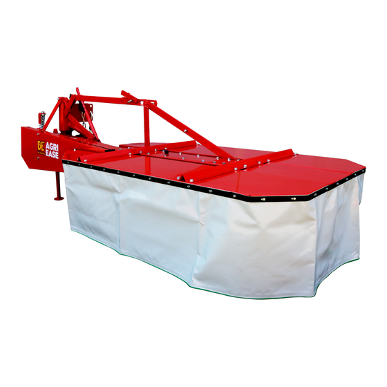
- Page 1 DRUM MOWER BE-Z175 OPERATIONS & PARTS MANUAL FOR MODELS: • BE-Z175 PURCHASE DATE MODEL NO. SERIAL NUMBER DEALER...
-
Page 2: Table Of Contents
TABLE OF CONTENTS PREFACE INTENDED USE SAFETY LABELS GENERAL OPERATING SERVICE STORAGE MOWER SERVICING MAINTENANCE ASSEMBLING MOWER INFORMATION ON DEFECTS AND MALFUNCTION SPECIFICATION DISASSEMBLY, WITHDRAWAL FROM USE AND ENVIRONMENTAL PROTECTION NOTES PARTS CATALOG WARRANTY CARD... -
Page 3: Preface
Mower BE-Z175 should operate with tractors of towed weight of at least 9 kN, e.g.: Ursus C-360, MF 255, Ursus 4512. The mower can be used on meadows and stone-free fields, on flat or slightly undulating fields with gradient of up to 12 °. - Page 4 It is forbidden to transport any personnel or loads on the machine or the tractor during transportation and operation • For driving on public roads make sure to sure to follow relevant road traffic regulations and fit the mower with required warning light devices and warning triangle for slow-moving vehicles. BE-Z175 USER MANUAL...
- Page 5 On belt gear guard F) Do not open and remove the guarding until the engine is running G) Do not stay nearby lift links when controlling the lift On linkage frame H) Keep a safe distance from the machine BE-Z175 USER MANUAL...
- Page 6 Tightener angle bar (sticker) indicator U-joint shaft location Linkage frame (sticker) NO MACHINE LIFTING WITH Linkage frame (sticker) Linkage frame (sticker) REVS ON Direction and nominal rotational Power input speed of power input connection connection cover (sticker) BE-Z175 USER MANUAL...
- Page 7 Safety Device Fig. 1. ROTARY MOWER BE-Z175: 1- Safety curtain, 2 - curtain, 2 - curtain frame, 3 - main frame, 4 - tension member, 5 - latch, 6 - guard, 7 - linkage frame, 8 - sliding disc, 9 - working drum, 10 - knife, 11 - tractor lower link, 12 - safety device, 13 - transport beam, 14 - roof guard, 15 - safety chain, 16 - U-joint shaft, 17 - central frame.
-
Page 8: Operating Service
= 2050 rpm (BE-Z175) FIG. 2. MOWER DRIVE DIAGRAM: 1 - U-joint shaft, 2 - driving head shaft, 3 - belt-and-pulley drive, 4 - bevel-... - Page 9 Use of U-joint shaft with parameters other than recommended by manufacturer of the machine may cause its overloading and emergency damage or split of its both parts during machine lifting and pose risk to service technicians and personnel around. BE-Z175 USER MANUAL...
- Page 10 Failure to follow the above recommendations may cause risk related to a sudden self-acting turn of the mower in relation to its linkage frame. Such turn may occur after unlocking of safety elements (transport beam or safety device). In order to move the mower to transport position do the following (Fig. 5): BE-Z175 USER MANUAL...
- Page 11 Check crosswise leveling of the mower (lower linkage frame pivots should be at the same height above the ground), • Detach transport beam (1) from upper pivot (4) of linkage frame and put on yoke (2) hook, while with BE-Z175 USER MANUAL...
- Page 12 • Put latch (6) in upper position (Fig. 7), • Install knives; on working drums, install a set of knives for BE-Z175 of the same weight, as otherwise the drum will become unbalanced which may cause mower damage, • Install U-joint shaft (see Installing U-joint shaft).
- Page 13 D of 8 mm in thickness or (44 mm) with mounted spacer ring D of 12 mm in thickness; 1 - resistance disc, 2 - hub, 3 - special bolt M 12 x 25, 4 - sliding disc, 5 -bolt M10 x 30, 6 - tab washer, 7 - resistance disc. BE-Z175 USER MANUAL...
- Page 14 CAUTION!!! Due to possible damage of the mower, do not allow: • Exceeding tractor PTO shaft rotational speed above 600 rpm, • Lifting the mower with revs off and drums rotating, • Mowing when tractor is driven backwards (as then the safety device is disabled). BE-Z175 USER MANUAL...
- Page 15 Remove ball-and-socket joints of tractor lower links from linkage frame pivots. RESIDUAL RISK DESCRIPTION Despite the fact that manufacturer, assumes responsibility for design and marking of rotary mowers BE-Z175 in order to eliminate risks during operation, and also during servicing and maintenance, some risk elements are unavoidable, though.
-
Page 16: Mower Servicing
• Protect the mower from being accessed by children, residual risk can be eliminated when using rotary mowers BE-Z175 without posing any risk to people and environment. CAUTION! Residual risk may occur if specified recommendations and instructions are not followed. - Page 17 (all pcs with the same dimension marking and trademark). BE-Z175 Fig. 16. V-belt tightener: 1 - adjustment nuts, 2 - tightener spring, 3 - tightener indicator bar, 4 - tightener bracket, S (dimension)= 0.5-3 mm. BE-Z175 USER MANUAL...
-
Page 18: Maintenance
Every 10-15 working hours check grease level through vent hole (using clean dipstick). Correct grease level should be 50-60 mm from the bottom of gear box. In case if grease level is reduced, first remove the cause of leakage and then fill up. Grease volume in gear box: BE-Z175 - 8+10 dm3. •... -
Page 19: Assembling Mower
ASSEMBLING MOWER The manufacturer delivers mower BE-Z175 in complete condition, with cutting unit cover removed. User (purchaser) of the mower is responsible for installation of cutting unit cover. WARNING!!! Operation without installed cutting unit cover or with damaged cover or safety curtain lifted, is forbidden. -
Page 20: Information On Defects And Malfunction
Excessive inter-tooth clearance Worn gear wheels Adjust using spacers Mower loses knives Worn knife holders Replace holders SPECIFICATION Operational data for mower BE-Z175 is given in Table 2. Table 2. Operational data TECHNICAL PARAMETERS UNIT OF MEASURE DATA Model according to KTM... -
Page 21: Disassembly, Withdrawal From Use And Environmental Protection
Delivery through a shipping company (large parts or assemblies) The manufacturer reserves the right to make design changes of parts given in each assembly drawing in parts catalogue. It may be impossible to update such changes in instruction manual and parts catalogue on regular basis. BE-Z175 USER MANUAL... - Page 22 Figure K1. Main frame body and cutting unit drive BE-Z175 USER MANUAL...
- Page 23 Right bearing housing 5-178-010-190/2 5-178-010-658 5-178-010-658/2 Welded cover 5-178-010-048 5-178-010-658/3 5-178-010-645 5-178-010-645/2 Welded main frame 5-178-010-063 5-178-010-645/3 5-178-010-235 5-178-010-235/2 Shackle, set 5-178-010-124 5-178-010-235/3 5-178-010-250 5-178-010-250/2 Pulley, small 5-178-010-089 5-178-010-250/3 5-178-010-263 5-178-010-263/2 Drive shaft 5-178-010-263/1 5-178-010-263/3 5-178-010-276 5-178-010-276 BE-Z175 USER MANUAL...
- Page 24 Ball bearing 6305 PN-85/M-86100 Ball bearing 6206 PN-85/M-86100 Ball bearing 6305-2Z-C3 PN-85/M-86100 Ball bearing 206-1Z-C3 PN-85/M-86100 Spring retaining ring Z25 PN-81/M-85111 Spring retaining ring Z30 PN-81/M-85111 Spring retaining ring W62 PN-81/M-85111 Sealing ring A25x52x10 PN-72/M-86964 Sealing ring A30x52x10 PN-72/M-86964 BE-Z175 USER MANUAL...
- Page 25 Spring washer 14,2Fe/Zn9 PN-77/M-82008 Bolt M10x35-8.8-B-Fe/Zn8c PN-85/M-82105 Spring washer 12,2Fe/Zn9 PN-77/M-82008 Bolt M12x30-8.8-B-Fe/Zn8c PN-85/M-82105 Bolt M14x30-8.8-B-Fe/Zn8c PN-85/M-82105 Nut M10-8-B-Fe/Zn8c PN-86/M-82144 Nut M12-8-B-Fe/Zn8c PN-86/M-82144 Retaining pin Ø6x16 PN 85021 Washer 10,4-Fe/Zn9 PN-77/M-82008 Spring washer 10,2Fe/Zn9 PN-78/M-82005 Two-hole bent washer 5-178-010-632 BE-Z175 USER MANUAL...
- Page 26 Figure K2. Cutting unit and bearings BE-Z175 USER MANUAL...
- Page 27 5-178-020-666 Gear wheel, small 5-178-020-666/2 5-178-020-666/3 Parallel key 5-178-010-790 5-178-010-790 Working wheel hub 5-178-010-790/3 5-178-010-309 Knife holder complete 5-178-010-109 Drum cover complete 5-178-010-109 5-178-010-775 Sliding disc hub 5-178-010-7751 5-178-010-340 Resistance disc complete 5-178-010-340/2 5-178-010-3403 Drum cover 5-178-010-365 BE-Z175 USER MANUAL...
- Page 28 Ball bearing 6210-2Z-C3 PN-85/M-86100 Ball bearing 6305-ZZ lub 2RS PN-85/M-86100 Spring retaining ring Z45 PN-81/M-85111 Sealing ring B40x62x10 PN-72/M-86965 Felt seal 5x8x12 PN-77/M-86012 5-178-010-812 Pressure ring 50178-010-812/3 Bolt M10x30-8.8-B-Fe/Zn8c Pn-85/M-82105 Nut M12-8-B-Fe/Zn8c PN-86/M-82144 Spring washer 10,2Fe/Zn9 PN-77/M-82008 BE-Z175 USER MANUAL...
- Page 29 Table 2. Cutting unit and bearings (continued) QUANTITY ITEM NO. PART NUMBER PART NAME REMARKS OR STANDARD BE-Z175 IN FIG. 1,65 M Spring washer 12,2Fe/Zn9 PN-85/M-82105 Bolt M10x20-8.8-B-Zn PN-85/M-82105 Bolt M10x30-8.8-B-Zn PN-85/M-82105 Use together with dist. ring pos. 5 BE-Z175 USER MANUAL...
- Page 30 Fig K3. Drive train and central beam BE-Z175 USER MANUAL...
- Page 31 5-178-020-144/2 5-178-020-280 Rear cover, guard set 5-178-020-280/60 5-178-020-280/80 5-178-020-144/3 5-178-020-157 5-178-020-157/2 5-178-020-293 Front cover, guard set 5-178-020-293/60 5-178-020-293/80 5-178-020-157/3 5-178-020-172 Key carrier 5-178-020-172/2 5-178-020-185 5-178-020-185/2 Pulley 5-178-020-191 5-178-020-185/3 Key carrier pin 5-178-020-198 Sleeve 5-178-020-205 Coupling spring 5-178-020-218 BE-Z175 USER MANUAL...
- Page 32 5-178-020-355/3 Bolt M14x260 5-178-020-348 5-178-020-350 Safety device spring 5-178-020-500 5-178-020-363 Transport beam, set 5-178-020-363/60 5-178-020-363/80 Spring seat of safety device 5-178-020-355/3 5-178-020-409 Angle piece 5-178-020-409/3 Spring seat of safety device 5-178-020-307/3 5-178-020-017 5-178-020-017/2 Stud bolt 5-178-020-020 5-178-020-017/3 BE-Z175 USER MANUAL...
- Page 33 Ball bearing 6207-2RS PN-85/M-86100 Ball bearing 6206-2RS PN-85/M-86100 Ball beaing 6007-2RS PN-86/M-86100 Ball bearing 6207-2RS PN-85/M-86100 Parallel key A8x7x56 PN-70/M-85005 Parallel key A10x9x65 PN-70/M-85005 Spring retaining ring Z35 PN-81/M-85111 Spring retaining ring W75 PN-81/M-85111 Spring retainging ring Z45 PN-81/M-85111 BE-Z175 USER MANUAL...
- Page 34 Split pin S-Zn Ø5x28 PN-76//M-82008 Pin Ø18x45 5-178-020-821 Pin Ø16x40 5-178-020-822 Nut M8-6-B-Fe/Zn8C PN-86/M-82144 7103056CE007007 Optional equipment U-joint shaft 7143-066-CE-00-096 Optional equipment 5-178-020-760 Support 5-178-020-760/2 Pin Ø30 5-178-020-823 Split cotter 5-178-020-289 Pin Ø30 with inner thread 5-178-020-824 BE-Z175 USER MANUAL...
- Page 35 Fig K4. Linkage BE-Z175 USER MANUAL...
- Page 36 5-178=020-096 5-178-020-096 5-178-020-096/1 Rear shackle (60) 5-178-020-096/1 (80) 5-178-020-103 Front link connector 5-178-020-103/1 Pin 25h9x55 5-178-020-825 Pin 25h9x500 5-178-020-825/1 5-178-020-656 Linkage frame, set 5-178-020-656/2 5-178-020-656/3 5-178-020-131 Pivot 5-178-020-131/2 5-178-020-131/3 Latch, set 5-178-020-220 Hook 5-178-020-261 Chain, set 5-178-020-274 BE-Z175 USER MANUAL...
- Page 37 Bolt M12x85-8.8-B-Fe/Zn8C PN-85/M-82101 Bolt M14x1,5x100 5-178-020-827 Self-locking nut M12-8-B-Fe/Zn8c PN-86/M-82175 Self-locking nut M14x1,5-8-B-Fe/Zn8c PN-86/M-82175 Nut M20x1,5-0, 6B PN-85/M-82153 Self-locking nut M20x1,5-8-B-Fe/Zn8c PN-86/M-82175 Washer 22,5 PN-63/M-82004 Washer 25,5 PN-63/M-82004 Split pin S-Zn Ø5x30 PN-76/M-82001 Spring pricker A11x50 5-178-031-045 BE-Z175 USER MANUAL...
- Page 38 Fig K5. Linkage with replaceable pins BE-Z175 USER MANUAL...
- Page 39 Hook 5-178-020-261 Chain, set 5-178-020-274 Washer 22,5 PN-63/M-82004 Spring pricker A11x50 5-178-031-045 Replaceable pin 5-178-020-831/2 Self-locking nut M24x1,5 5-178-020-539 Shoulder bolt, set 5-178-020-833 Compression spring 5-178-020-834 Pin cord 5-178-020-835 Split pin S-Zn Ø6x40 PN-76/M-82001 Washer 25,5 PN-63/M-82004 BE-Z175 USER MANUAL...
- Page 40 Fig K7. Metal cover set. BE-Z175 USER MANUAL...
- Page 41 5-178-030-196/2 Curtain 5-178-030-133 5-178-030-196/3 Side cover, set 5-178-030-101 5-178-030-272 5-178-030-272/2 Curtain bar 5-178-030-272/1 5-178-030-272/3 5-178-030-244 Supporting bar 5-178-030-244/2 5-178-030-257 5-178-030-257/2 Corner bar 5-178-030-207 5-178-030-257/2/K 5-178-030-257/2/D 5-178-030-231 5-178-030-231/2 Middle cover 5-178-030-174 5-178-030-231/3 Widened washer 5-178-030-170 Bolt M6x16-8.8-B-Fe/ PN-85/M-82105 BE-Z175 USER MANUAL...
- Page 42 PART NUMBER PART NUMBER REMARKS OR STANDARD BE-Z175 IN FIG. 1,65 M Bolt M10x20-8.8-B-Fe/Zn8C PN-85/M-82105 Bolt M10x25-8.8-B-Fe/Zn8C PN-85/M-82105 Nut M6-8-B-Fe/Zn8C PN-86/M-82105 Nut M6-8-B-Fe/Zn8C PN-86/M-82144 Washer 6,5 Fe/ZnC PN-59/M-82030 Washer 10,5 Fe/Zn9 PN-59/M-82030 Spring washer 10, 2 Fe/Zn9 PN-77/M-82008 BE-Z175 USER MANUAL...
- Page 43 Fig K8. Elastic cover set. BE-Z175 USER MANUAL...
- Page 44 1,65 M 5-178-040-014 Elastic cover, set (poz. 1-9) 5-178-040-014/1 5-178-040-030 Left frame 5-178-040-030/1 5-178-040-042 Right frame 5-178-040-042/2 5-178-040-055 Curtain 5-178-040-055/1 Side cover, set 5-178-040-027 Nylon braided cord without core BN-72/75976-05 7023-532-11-1R-221-5-8 Widened washer 5-178-040-170 Bolt M8x20-5.8-B-Fe/Zn8C PN-85/M-82105 BE-Z175 USER MANUAL...
-
Page 45: Warranty Card
Vast damage caused by random events or other occurrence for which the Warranter cannot be held responsible • Lack of required records or changes in Warranty Card • Misuse of the product or installation or use not in accordance with instruction manual. BE-Z175 USER MANUAL... - Page 46 B RA B E R EQ .CO M WGSALES@BRABEREQ.COM PHONE: 604-850-7770 FAX: 604-850-7774 TOLL FREE PHONE: 1-877-588-3311 TOLL FREE FAX: 1-800-665-7334 BE-Z175 USER MANUAL...
Need help?
Do you have a question about the BE-Z175 and is the answer not in the manual?
Questions and answers