Sign In
Upload
Manuals
Brands
Mitsubishi Electric Manuals
Controller
MR-E-200A-KH003
Mitsubishi Electric MR-E-200A-KH003 Manuals
Manuals and User Guides for Mitsubishi Electric MR-E-200A-KH003. We have
2
Mitsubishi Electric MR-E-200A-KH003 manuals available for free PDF download: Instruction Manual
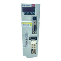
Mitsubishi Electric MR-E-200A-KH003 Instruction Manual (350 pages)
Brand:
Mitsubishi Electric
| Category:
Servo Drives
| Size: 6 MB
Table of Contents
Table of Contents
13
Functions and Configuration
18
Introduction
18
Function Block Diagram
19
Servo Amplifier Standard Specifications
20
Model Code Definition
23
Parts Identification
24
Servo System with Auxiliary Equipment
26
Signals and Wiring
32
Standard Connection Example
33
Internal Connection Diagram of Servo Amplifier
40
Connectors and Signal Arrangements
41
Signal Explanations
44
Detailed Description of the Signals
50
Speed Control Mode
57
Servo Amplifier Connectors (CNP1, CNP2) Wiring Method (When MR-ECPN1-B and MR-ECPN2-B of an Option Are Used.)
76
Instructions for the 3M Connector
79
Operation
80
When Switching Power on for the First Time
80
Startup
81
Selection of Control Mode
81
Position Control Mode
81
Internal Speed Control Mode
83
Parameters
86
Parameter List
86
Parameter Write Inhibit
86
Lists
87
Item List
87
Details List
90
Detailed Description
109
Electronic Gear
109
Analog Monitor
110
Using Forward/Reverse Rotation Stroke End to Change the Stopping Pattern
113
Alarm History Clear
113
Position Smoothing
114
Display and Operation
116
Display Flowchart
116
Status Display
117
Display Examples
117
Status Display List
118
Changing the Status Display Screen
119
Diagnostic Mode
120
External I/O Signal Display
120
Alarm Mode
121
Parameter Mode
122
External I/O Signal Display
123
Output Signal (DO) Forced Output
125
Test Operation Mode
126
Mode Change
126
Jog Operation
127
Positioning Operation
128
Motor-Less Operation
129
General Gain Adjustment
130
Different Adjustment Methods
130
Adjustment on a Single Servo Amplifier
130
Adjustment Using MR Configurator (Servo Configuration Software)
131
Auto Tuning
131
Auto Tuning Mode 1
131
Auto Tuning Mode Operation
133
Adjustment Procedure by Auto Tuning
134
Response Level Setting in Auto Tuning Mode
135
Manual Mode 1 (Simple Manual Adjustment)
136
Adjustment by Manual Mode 1
136
Interpolation Mode
139
Special Adjustment Functions
140
Function Block Diagram
140
Machine Resonance Suppression Filter
140
Adaptive Vibration Suppression Control
142
Low-Pass Filter
143
Gain Changing Function
144
Applications
144
Function Block Diagram
144
Parameters
145
Gain Changing Operation
147
Inspection
150
Troubleshooting
152
Trouble at Start-Up
152
Position Control Mode
152
Internal Speed Control Mode
155
When Alarm or Warning Has Occurred
156
Alarms and Warning List
156
Remedies for Alarms
157
Remedies for Warnings
162
Outline Dimension Drawings
164
Servo Amplifiers
164
Connectors
168
Characteristics
172
Overload Protection Characteristics
172
Power Supply Equipment Capacity and Generated Loss
172
Dynamic Brake Characteristics
174
Encoder Cable Flexing Life
175
Inrush Currents at Power-On of Main Circuit and Control Circuit
175
Options and Auxiliary Equipment
176
Options
176
Regenerative Options
176
Cables and Connectors
181
Analog Monitor, RS-232C Branch Cable (MR-E3CBL15-P)
183
MR Configurator (Servo Configurations Software)
203
Auxiliary Equipment
204
Selection Example of Wires
204
Circuit Breakers, Fuses, Magnetic Contactors
206
Power Factor Improving Reactors
206
Relays
207
Surge Absorbers
207
Noise Reduction Techniques
208
Leakage Current Breaker
215
EMC Filter
217
Servo Motor
218
Compliance with the Overseas Standards
218
Compliance with EC Directives
218
Conformance with UL/C-UL Standard
218
Introduction
219
Features of Servo Motor
219
Rating Plate
219
Parts Identification
220
Electromagnetic Brake Characteristics
221
Servo Motor Shaft Shapes
222
Installation
223
Installation Orientation
224
Load Remove Precautions
224
Permissible Load for the Shaft
225
Protection from Oil and Water
225
Cable
226
Inspection
227
Life
227
Machine Accuracies
228
Connectors Used for Servo Motor Wiring
229
Selection of Connectors
229
Wiring Connectors (Connector Configurations a B C)
229
Wiring Connectors (Connector Configurations D, E, F, G, H)
231
Connector Outline Drawings
234
Hf-Ke W1-S100
240
Standard Specifications
240
Electromagnetic Brake Characteristics
242
Servo Motors with Special Shafts
243
Outline Dimension Drawings
244
Hf-Se Jw1-S100
251
Model Name Make up
251
Standard Specifications
252
Electromagnetic Brake Characteristics
254
Servo Motors with Special Shafts
255
Outline Dimension Drawings
256
Appendix
324
App. 1 Change of Connector Sets to the Rohs Compatible Products
324
App. 2 HF-KE HF-SE Servo Motor
325
Advertisement
Mitsubishi Electric MR-E-200A-KH003 Instruction Manual (352 pages)
General-Purpose AC Servo EZMOTION MR-E Super General-Purpose Interface
Brand:
Mitsubishi Electric
| Category:
Controller
| Size: 8 MB
Table of Contents
Safety Instructions
3
Additional Instructions
5
Transportation and Installation
5
General Instruction
8
Compliance with Ec Directives
10
Conformance with Ul/C-Ul Standard
12
Table of Contents
16
Functions and Configuration
19
Introduction
19
Function Block Diagram
20
Servo Amplifier Standard Specifications
21
Function List
22
MR Configurator (Servo Configurations Software)
23
Model Code Definition
24
Parts Identification
25
Servo System with Auxiliary Equipment
27
Installation
29
Environmental Conditions
29
Signals and Wiring
33
Standard Connection Example
34
Position Control Mode
34
External Power Supply
34
Internal Speed Control Mode
40
Internal Connection Diagram of Servo Amplifier
41
Connectors and Signal Arrangements
42
Signal Explanations
45
Output Signals
48
Power Supply
50
Detailed Description of the Signals
51
Common Line
61
Encoder Pulse Output
64
Output Pulse
65
Power Supply Cable Wiring Diagrams
70
Pin Signal
72
Alarm Occurrence
75
Power off
75
Operation
81
Startup
82
Speed Control Mode
97
Set Content
112
Display and Operation
117
Display Flowchart
117
Status Display
118
Status Display List
119
Changing the Status Display Screen
120
Diagnostic Mode
121
External I/O Signal Display
124
General Gain Adjustment
131
Special Adjustment Functions
141
Gain Changing Operation
148
Troubleshooting
153
Trouble at Start-Up
153
Outline Dimension Drawings
165
Overload Protection Characteristics
173
Options and Auxiliary Equipment
177
Outline Drawing
180
Connection of Servo Amplifier and Servo Motor
188
Connection Diagram
193
Communication Cable
198
Specifications
204
Auxiliary Equipment
205
Selection Example of Wires
205
Circuit Breakers, Fuses, Magnetic Contactors
207
Power Factor Improving Reactors
207
Relays
208
Surge Absorbers
208
Noise Reduction Techniques
209
Outline Drawing
213
Leakage Current Breaker
216
EMC Filter
218
Connection Example
218
Servo Motor
219
Compliance with the Overseas Standards
219
Compliance with EC Directives
219
Conformance with UL/C-UL Standard
219
Introduction
220
Features of Servo Motor
220
Rating Plate
220
Parts Identification
221
Electromagnetic Brake Characteristics
222
Servo Motor Shaft Shapes
223
Installation
224
Installation Orientation
225
Permissible Load for the Shaft
226
Cable
227
Inspection
228
Life
228
Machine Accuracies
229
Reference Diagram
229
Connectors Used for Servo Motor Wiring
230
Selection of Connectors
230
Wiring Connectors (Connector Configurations a B C)
230
Wiring Connectors (Connector Configurations D, E, F, G, H)
230
Hf-Se Jw1-S100
230
Model Name Make up
237
Standard Specifications
241
Torque Characteristics
242
Electromagnetic Brake Characteristics
243
Servo Motors with Special Shafts
244
Outline Dimension Drawings
245
Model Code Definition
264
Servo System with Auxiliary Equipment
266
Torque Control Mode
270
Connectors and Signal Arrangements
272
Input Signals
274
Control Mode
276
Trouble at Start-Up
322
Torque Characteristics
332
Advertisement
Related Products
Mitsubishi Electric EZMOTION MR-E Super MR-E-200AG-QW003
Mitsubishi Electric MR-E-200A
Mitsubishi Electric MR-E-200AG
Mitsubishi Electric MR-E-200AG-KH003
Mitsubishi Electric EZMOTION MR-E Super MR-E-20A-QW003
Mitsubishi Electric EZMOTION MR-E Super MR-E-20AG-QW003
Mitsubishi Electric MR-E-20A
Mitsubishi Electric MR-E-20AG
Mitsubishi Electric MR-E-20A-KH003
Mitsubishi Electric MR-E-20AG-KH003
Mitsubishi Electric Categories
Air Conditioner
Controller
Projector
Inverter
Heat Pump
More Mitsubishi Electric Manuals
Login
Sign In
OR
Sign in with Facebook
Sign in with Google
Upload manual
Upload from disk
Upload from URL