Table of Contents
Advertisement
Quick Links
Advertisement
Table of Contents

Subscribe to Our Youtube Channel
Related Manuals for Kyocera DP-110


Summary of Contents for Kyocera DP-110
- Page 1 DP-110 SERVICE MANUAL Published in June 2009 3LJSM061 Rev.1...
- Page 2 CAUTION RISK OF EXPLOSION IF BATTERY IS REPLACED BY AN INCORRECT TYPE. DISPOSE OF USED BATTERIES ACCORDING TO THE INSTRUCTIONS. It may be illegal to dispose of this battery into the municipal waste stream. Check with your local solid waste officials for details in your area for proper disposal. ATTENTION IL Y A UN RISQUE D’EXPLOSION SI LA BATTERIE EST REMPLACEE PAR UN MODELE DE TYPE INCORRECT.
- Page 3 Revision history Revision Date Replaced pages Remarks 25 June 2009 1-1-1, 1-3-1 to 1-3-14, 1-5-2, 2-2-1...
- Page 4 This page is intentionally left blank.
- Page 5 Safety precautions This booklet provides safety warnings and precautions for our service personnel to ensure the safety of their customers, their machines as well as themselves during maintenance activities. Service personnel are advised to read this booklet carefully to familiarize themselves with the warnings and precautions described here before engaging in maintenance activities.
- Page 6 Safety warnings and precautions Various symbols are used to protect our service personnel and customers from physical danger and to prevent damage to their property. These symbols are described below: DANGER: High risk of serious bodily injury or death may result from insufficient attention to or incorrect compliance with warning messages using this symbol.
- Page 7 1.Installation Precautions WARNING • Do not use a power supply with a voltage other than that specified. Avoid multiple connections to one outlet: they may cause fire or electric shock. When using an extension cable, always check that it is adequate for the rated current....................•...
- Page 8 2.Precautions for Maintenance WARNING • Always remove the power plug from the wall outlet before starting machine disassembly....• Always follow the procedures for maintenance described in the service manual and other related brochures............................• Under no circumstances attempt to bypass or disable safety features including safety mechanisms and protective circuits.
- Page 9 • Do not remove the ozone filter, if any, from the copier except for routine replacement..... • Do not pull on the AC power cord or connector wires on high-voltage components when removing them; always hold the plug itself...................... •...
- Page 10 This page is intentionally left blank.
-
Page 11: Table Of Contents
CONTENTS 1-1 Specifications 1-1-1 Specifications............................1-1-1 1-1-2 Parts names............................1-1-2 1-1-3 Machine cross section ..........................1-1-3 1-2 Installation 1-2-1 Installation environment ..........................1-2-1 1-2-2 Unpacking ...............................1-2-2 (1) Unpacking ............................1-2-2 (2) Removing the tapes and the spacer....................1-2-3 1-3 Maintenance Mode 1-3-1 Maintenance mode ..........................1-3-1 (1) Executing a maintenance item ......................1-3-1 (2) Maintenance modes item list......................1-3-2 (3) Contents of the maintenance mode items..................1-3-3 1-4 Troubleshooting... - Page 12 This page is intentionally left blank.
-
Page 13: Specifications
3LJ-1 1-1 Specifications 1-1-1 Specifications Original feed method ...... Automatic feed Supported original types ....Sheet originals Original sizes ........Maximum: Legal/A4 Minimum: Statement/A5 Original weights ......Simplex: 50 to 120 g/m Duplex: 50 to 110 g/m Loading capacity ......50 sheets (50 to 80 g/m ) maximum Power source........ -
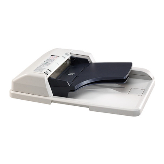
Page 14: Parts Names
1-1-2 Parts names Figure 1-1-1 Top cover Original width guides Original table Original eject table Original stopper Opening handle 1-1-2... -
Page 15: Machine Cross Section
1-1-3 Machine cross section Original path Figure 1-1-2 Machine cross section Original feed section Original conveying section Original switchback section 1-1-3... - Page 16 This page is intentionally left blank. 1-1-4...
-
Page 17: Installation Environment
1-2 Installation 1-2-1 Installation environment Installation location (Be based on the machine establishment place.) Avoid direct sunlight or bright lighting. Ensure that the photo-conductor will not be exposed to direct sunlight or other strong light when removing paper jams. Avoid locations subject to high temperature and high humidity or low temperature and low humidity; an abrupt change in the environmental temperature;... -
Page 18: Unpacking
1-2-2 Unpacking (1) Unpacking Figure 1-2-1 Unpacking Document processor (DP) Original mat Plastic bag 300 × 800 10. Adjustment original Plastic sheet 800 × 800 11. Plastic bag 300 × 500 Side pad R 12. Plastic bag 240 × 350 Side pad L 13. -
Page 19: Removing The Tapes And The Spacer
(2) Removing the tapes and the spacer Procedure 1. Remove three tapes A. 2. Open the top cover and then remove the spacer. 3. Remove four tapes B. Tape B Tape B Tape B Tapes B Tape A Top cover Tape A Spacer Tape A... - Page 20 This page is intentionally left blank. 1-2-4...
-
Page 21: Maintenance Mode
3LJ-1 1-3 Maintenance Mode 1-3-1 Maintenance mode The machine is equipped with a maintenance function which can be used to maintain and service the machine. (1) Executing a maintenance item Start Enter “10871087” using Maintenance mode is entered. the numeric keys. Enter the maintenance item number using the cursor left/right keys The maintenance item is... -
Page 22: Maintenance Modes Item List
3LJ-1 (2) Maintenance modes item list Section Item Content of maintenance item Initial setting General U001 Exiting the maintenance mode Optical U068 Adjusting the scanning position for originals from the DP U070 Adjusting the DP magnification U071 Adjusting the DP scanning timing 0/0/0/0/0 U072 Adjusting the DP center line... -
Page 23: Contents Of The Maintenance Mode Items
3LJ-1 (3) Contents of the maintenance mode items Maintenance Description item No. Exiting the maintenance mode U001 Description Exits the maintenance mode and returns to the normal copy mode. Purpose To exit the maintenance mode. Method Press the start key. The normal copy mode is entered. Adjusting the scanning position for originals from the DP U068 Description... - Page 24 3LJ-1 Maintenance Description item No. Adjusting the DP magnification U070 Description Adjusts the DP original scanning speed. Purpose Make the adjustment if the magnification is incorrect in the auxiliary scanning direction when the DP is used. Method 1. Press the start key. Display Description Setting...
- Page 25 3LJ-1 Maintenance Description item No. Adjusting the DP scanning timing U071 Description Adjusts the DP original scanning timing. Purpose Make the adjustment if there is a regular error between the leading or trailing edges of the original and the copy image when the optional DP is used. Method 1.
- Page 26 3LJ-1 Maintenance Description item No. Adjustment: Trailing edge registration U071 1. Press the system menu/counter key. 2. Place an original on the DP and press the start key to make a test copy. 3. Press the system menu/counter key. 4. Change the setting value using the cursor left/right keys or numeric keys. For copy example 1, increase the value.
- Page 27 3LJ-1 Maintenance Description item No. Adjusting the DP center line U072 Description Adjusts the scanning start position for the DP original. Purpose Make the adjustment if there is a regular error between the centers of the original and the copy image when the optional DP is used.
- Page 28 3LJ-1 Maintenance Description item No. Setting DP reading position modification operation U087 Description The presence or absence of dust is determined by comparing the scan data of the original trailing edge and that taken after the original is conveyed past the DP original scanning position. If dust is identified, the DP original scanning position is adjusted for the following originals.
- Page 29 3LJ-1 Maintenance Description item No. Checking DP operation U203 Description Simulates the original conveying operation separately in the DP. Purpose To check the DP operation. Method 1. Press the start key. 2. Place an original in the DP if running this simulation with paper. 3.
- Page 30 3LJ-1 Maintenance Description item No. Checking the DP sensors U244 Description Displays the status of the respective sensors in the DP. Purpose To check if respective sensors in the DP operate correctly. Method 1. Press the start key. 2. Turn the respective sensors on and off manually to check the status. When a sensor is detected to be in the ON position, the display for that sensor will be highlighted.
- Page 31 3LJ-1 Maintenance Description item No. Adjusting margins for scanning an original from the DP U404 Description Adjusts margins for scanning the original from the DP. Purpose Make the adjustment if margins are incorrect when the optional DP is used. Caution Before making this adjustment, ensure that the following adjustments have been made in maintenance mode.
- Page 32 3LJ-1 Maintenance Description item No. Adjusting the scanner automatically U411 Description Uses the adjustment original suppled with DP and automatically adjusts the following items in the scanner and the DP scanning sections. Purpose To perform automatic adjustment of various items in the scanner and the DP scanning sections. Method 1.
- Page 33 3LJ-1 Maintenance Description item No. Checking/clearing counts by optional devices U905 Description Displays or clears the counts of DP. Purpose To check the use of DP. Also to clear the counts after replacing consumable parts. Method 1. Press the start key. Display Description No.
- Page 34 3LJ-1 This page is intentionally left blank. 1-3-14...
-
Page 35: Original Misfeed Detection
1-4 Troubleshooting 1-4-1 Original misfeed detection (1) Original misfeed indication When an original jams, the machine immediately stops operation and a message is shown on the machine operation panel. To remove the jammed original, open the top cover. To reset the original misfeed detection, open and close the top cover. 1-4-1... -
Page 36: Original Misfeed Detection Conditions
(2) Original misfeed detection conditions DP document sensor DP timing sensor Figure 1-4-1 Section Jam code Conditions Specified time The DP timing sensor does not turn on within specified time 647 pulses No original feed during the first sheet feeding (Retry 5 times). The DP timing sensor does not turn on within specified time 647 pulses during the second sheet feeding (Retry 5 times). -
Page 37: Paper Misfeeds
(3) Paper misfeeds Problem Causes/check procedures Corrective measures Defective DP timing sensor. Run maintenance item U244 and turn the DP timing sensor on An original jams in and off manually. Replace the sensor if indication of the corre- DP is indicated dur- sponding sensor on the operation panel is not displayed in ing copying (no origi- reverse. -
Page 38: Electric Problems
1-4-2 Electric problems Problem Causes Check procedures/corrective measures Connection failure with DP Turn the main power switch off, investigate the DP connector con- The DP paper feed nection, and firmly connect the DP connector. connector. motor does not oper- ate. DP connector Defective harness between Reinsert the connector. - Page 39 Problem Causes Check procedures/corrective measures Defective harness between Reinsert the connector. Also check for continuity within the con- The switchback feed- switchback feedshift sole- nector harness. If none, remedy or replace the harness. shift solenoid does noid and DP driver PWB not operate.
-
Page 40: Mechanical Problems
1-4-3 Mechanical problems Problem Causes/check procedures Corrective measures Connection failure with DP connector. Turn the main power switch off, investigate No primary original feed. the DP connector connection, and firmly connect the DP connector. DP connector The surfaces of the forwarding pulley, feed Check and clean them with isopropyl alcohol pulley or separation pad are dirty with paper if they are dirty (see page 1-5-4 or page 1-5-... -
Page 41: Assembly And Disassembly
1-5 Assembly and Disassembly 1-5-1 Precautions for assembly and disassembly (1) Precautions Before starting disassembly, press the Power key on the operation panel to off. Make sure that the Power lamp is off before turning off the main power switch. And then unplug the power cable from the wall outlet. When handling PWBs (printed wiring boards), do not touch parts with bare hands. -
Page 42: Outer Covers
3LJ-1 1-5-2 Outer covers (1) Detaching and refitting the DP rear cover and DP front cover Procedure 1. Open the top cover. 2. Remove two screws. DP rear cover Top cover 3. Unhook the hook and then remove the DP Screw rear cover. -
Page 43: Pwbs
1-5-3 PWBs (1) Detaching and refitting the DP driver PWB Follow the procedure below to check or replace the DP driver PWB. Procedure 1. Remove the DP rear cover (See page 1-5- 2. Remove eight connectors from the DP driver PWB. 3. -
Page 44: Feed Section
1-5-4 Feed section (1) Detaching and refitting the feed pulley and forwarding pulley Follow the procedure below to clean or replace the feed pulley or forwarding pulley. Procedure 1. Remove the DP rear cover and DP front cover (See page 1-5-2). 2. - Page 45 6. Remove the forwarding pulley assembly. Forwarding pulley assembly Figure 1-5-6 Detaching the feed pulley Spring 7. Remove the stopper A. 8. Remove the feed pulley assembly from the Spring collar S LF holder. 9. Remove the stopper B. Feed pully Stopper B 10.
- Page 46 Detaching the forwarding pulley 12. Remove the PF stopper from the LF holder. 13. Remove the stopper. LF holder 14. Pull out the LF shaft and then remove the LF gear 18, forwarding feed joint gear and for- PF stopper warding pulley.
-
Page 47: Detaching And Refitting The Separation Pad Assembly
(2) Detaching and refitting the separation pad assembly Follow the procedure below to clean or replace the separation pad assembly. Procedure 1. Remove the forwarding pulley assembly (See page 1-5-4). 2. Remove the separation pad assembly. 3. Clean or replace the separation pad assem- bly. - Page 48 This page is intentionally left blank. 1-5-8...
-
Page 49: Original Feed Section
2-1 Mechanical construction 2-1-1 Original feed section The original feed section consists of the parts shown in figure. An original placed on the original table is conveyed to the original conveying section. Original is fed by the rotation of the forwarding pulley and feed pulley. Figure 2-1-1 Original feed section Forwarding pulley Separation mount... -
Page 50: Original Conveying Section
(1) Original conveying section The original conveying section consists of the parts shown in figure. A conveyed original is scanned by the optical section (CCD) of main machine when it passes through the DP contact glass of main machine. Figure 2-1-3Original conveying section Conveying roller A Conveying pulley Conveying bottom... -
Page 51: Original Switchback/Eject Sections
2-1-2 Original switchback/eject sections The original switchback/eject sections consists of the parts shown in figure. An original of which scanning is complete is ejected to the original eject table by the eject roller. In the case of duplex switchback scanning, an original is conveyed temporarily to the switchback tray and conveyed again to the original conveying section by the switchback roller. - Page 52 This page is intentionally left blank. 2-1-4...
-
Page 53: Electrical Parts Layout
3LJ-1 2-2 Electrical Parts Layout 2-2-1 Electrical parts layout (1) Electrical parts layout Machine front Machine inside Machine rear Figure 2-2-1 Electrical parts layout DP driver PWB..........Consists the solenoids and clutch driver circuit and wiring relay circuit. DP original sensor........Detects the presence of an original. DP timing sensor.......... - Page 54 This page is intentionally left blank. 2-2-2...
-
Page 55: Dp Driver Pwb
2-3 Operation of the PWBs 2-3-1 DP driver PWB Transistor DP paper feed clutch DP paper feed motor DP switchback Transistors pressure solenoid DP switchback Transistor feedshift solenoid DP open/close sensor DP timing sensor DP original sensor DP driver PWB Main machine Motor driver Scanner PWB... - Page 56 Figure 2-3-2DP driver PWB silk-screen diagram Connector Pin No. Signal Voltage Description MOT1A 0/24 V DC (pulse) DP paper feed motor drive pulse Connected to MOT2B 0/24 V DC (pulse) DP paper feed motor drive pulse the scanner MOT1B 0/24 V DC (pulse) DP paper feed motor drive pulse MOT2A 0/24 V DC (pulse) DP paper feed motor drive pulse (Machine)
- Page 57 Connector Pin No. Signal Voltage Description +24V4 24 V DC 24 V DC power source Connected to Ground the scanner PWB (Main machine) +3.3V1 3.3 V DC 3.3 V DC power source Connected to Ground the scanner TIMSWN 0/3.3 V DC DP timing sensor: On/Off PWB (Main ORGSWN...
- Page 58 This page is intentionally left blank. 2-3-4...
-
Page 59: Appendixes
2-4 Appendixes 2-4-1 Appendixes (1) Wiring diagram 2-4-1... - Page 60 This page is intentionally left blank. 2-4-2...
Need help?
Do you have a question about the DP-110 and is the answer not in the manual?
Questions and answers