Table of Contents
Advertisement
Quick Links
Distributed by: ABQ Industrial LP USA
Tel: +1 (281) 516-9292 / (888) 275-5772 eFax: +1 (866) 234-0451
Web: https://www.abqindustrial.net E-mail: info@abqindustrial.net
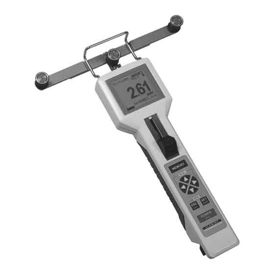
MODEL DTX
DIGITAL TENSION METER
Operating Manual
Distributed by: ABQ Industrial LP USA
Tel: +1 (281) 516-9292 / (888) 275-5772 eFax: +1 (866) 234-0451
Web: https://www.abqindustrial.net E-mail: info@abqindustrial.net
Advertisement
Table of Contents

Related Manuals for ELECTROMATIC DTX Series


Summary of Contents for ELECTROMATIC DTX Series
- Page 1 Distributed by: ABQ Industrial LP USA Tel: +1 (281) 516-9292 / (888) 275-5772 eFax: +1 (866) 234-0451 Web: https://www.abqindustrial.net E-mail: info@abqindustrial.net MODEL DTX DIGITAL TENSION METER Operating Manual Distributed by: ABQ Industrial LP USA Tel: +1 (281) 516-9292 / (888) 275-5772 eFax: +1 (866) 234-0451 Web: https://www.abqindustrial.net E-mail: info@abqindustrial.net...
-
Page 2: Table Of Contents
TABLE OF CONTENTS 01.0 Introduction ......................... 02 02.0 Overview of Operating And Display Elements ............03 03.0 Set-up ........................06 Charging the battery Turning the tension meter ON and OFF 04.0 Tension Meter Settings ....................07 Procedure Setting chart Material menu Password Factory Reset 05.0 Operation ........................ -
Page 3: Introduction
1.0 INTRODUCTION The DTX is supplied as a complete kit that includes: (1) Tension meter with accumulator and AC adapter with country adapters (EU, US, UK) (1) Certificate of compliance with the order 2.1 under EN 10204 (1) Operating Instructions (1) Carrying case NOTE: Unpack the tension meter and inspect it for shipping damage. - Page 4 Numeric display Adjusted material Info on material Battery status indicator diameter Damping Memory mode (data stored in the memory) Current reading Measurement unit MIN/MAX Alarm FIG. 2 Display with Bargraph Adjusted material Info on material Battery status indicator diameter Damping Memory mode (data stored in the memory) Current reading...
- Page 5 Graphic display Adjusted material diameter Battery status indicator Info on material Damping Memory mode (data Tension range stored in the memory) Measured values MAX.-alarm value as graph MIN.-alarm value Current reading Measurement unit MIN/MAX Alarm Alarm values FIG. 4 The Y-axis can be scaled with the buttons.
-
Page 6: Setup
3.0 SETUP The tension meter is delivered with a built-in rechargeable LiPo battery, which has been charged at the factory. The tension meter can only be switched on if the battery is still working, i.e. if the battery has enough charge. If the instrument does not power up or if the battery level indicator shows only one bar after power-up switching the tension meter on, the battery needs to be recharged. -
Page 7: Tension Meter Settings
4.0 TENSION METER SETTINGS Thumbpiece positions Pos. 2 Pos. 0 Pos. 1 FIG. 5 2 = Measurement position 0 = Adjustment position 1 = Threading position (guide rollers in their forward position Menu settings can be changed with the thumbpiece in Pos. - Page 8 Tension Meter settings chart Main Menu Submenu Settings Menu Description Material [1] to [11] Section 4.3 Material set up Cal. — [–10%] – [+10%] Section 5.7 Adjustment [numeric] • Measured value displayed as number and alarm monitoring [Bargraph] • Measured value displayed as number, bar graph trend Display —...
-
Page 9: Material Menu
Material Menu In the material menu you can make the settings for the selected material characteristics and perform the calibration. To perform the calibration, the weights for the selected calibration points must be available. Material Setup Submenu Settings Menu Description No. -
Page 10: Operation
5.0 OPERATION Requirements 1. Switch the tension meter on (Section 3.2) 2. Define the required tension meter settings (Section 4.2) 3. Select the desired material characteristic (Section 4.3) 4. Set the material thickness compensator (Section 5.2), if equipped 5. Bring the tension meter into the desired measuring position and carry out a zero adjustment as described in Section 5.3, if required. -
Page 11: Zero Adjustment Of The Measurement Position
Zero adjustment of the measurement position Each time the measurement position is changed, the tension meter will automatically perform a zero adjustment. If the tension meter does not display zero in its measuring position, perform a manual zero adjustment procedure. For this purpose, no material to be measured must have been inserted yet! Requirements: 1. - Page 12 To insert the material to be measured: 1. Push the thumbpiece in the direction of the arrow into its threading position 1 (1) until the outer guide rollers extend beyond the filament guide. 2. Position the material to be measured into the tension meter in such a way that it contacts the Filament guide and passes between the outer rollers and the middle measuring roller (1) .
-
Page 13: Damping
Numerical Display Display with bargraph Graphical Display FIG. 8 FIG. 9 FIG. 10 6. Press the button simultaneously to change the different display modes during the working mode. Do not let the thumbpiece snap back as this could affect the calibration and damage the instrument. -
Page 14: Alarm Function
The factory setting for the damping factor is 5. The average shown on the display is calculated as follows: 5 old measured values + 4 new measured values Damping can be changed in 9 steps from 01 = low damping: 1 old measured value + 8 new measured values to 9 = high damping: 8 old measured values + 1 new measured value... -
Page 15: Peak Value
3. Press the key to perform the calibration adjustment until the value on thedisplay corresponds to the weight suspended to the material. The adjustment can be performed in 1 % steps within the range from + 10% to –10%. 4. Press the button to save the determined value. -
Page 16: Creating A Material Characteristic
6.0 CREATING A MATERIAL CHARACTERISTIC The tension meter has been calibrated on material 1 according our factory procedure for a vertical material path and cannot be deleted or overwritten. The the materials and diameters are given in Section 2. Factory calibrations using customer supplied materials follow the same procedure. - Page 17 Requirements: 1. The thumbpiece must be in the adjustment position(4) (Fig. 6). 2. The material thickness compensator (if existing) must be set to the adjustment position (Section 5.2) 3. The unit for the material thickness must have been set (Section 4.3) To perform the calibration procedure: 1.
- Page 18 Step 2: Set the diameter This step is only required for tension meters with a material thickness compensator Step 3: Perform a zero adjustment with the tension meter in its measuring position Step 4: Calibrate calibration point 1 Insert material to be measured Step 5: Calibrate calibration point 2 Step 6:...
-
Page 19: Verifying The Calibration
Verifying the calibration When verifying the calibration, make sure to select the same material, calibration position and calibration points as used for creating the associated material characteristic. Otherwise, the precision of the measurements will not be sufficient. The tension meter has been calibrated on material 1 according our factory procedure for a vertical material path and cannot be deleted or overwritten. -
Page 20: Memory Functions
MEMORY FUNCTIONS The tension meter is delivered with 4 different memory modes. You can store up to 255 measurement series at one or more machine positions. The tension meter can store up to 60000 measured values. All saved measured values and statistic datas can be transferred to a PC (for further processing, e.g. - Page 21 Selecting the memory mode Requirements: 1. The tension meter has been switched on as described in chapter 3.3.2. 2. Open the menu by pressing the buttons simultaneously and select Memory Settings. 3. Select the desired memory mode in the user navigation. NOTE: If the memory already contains data, a message will inform you that the data will be deleted.
-
Page 22: Displaying The Saved Measured Values
Displaying the saved measured values 1. Press the RECALL buttons simultaneously to display the saved data. 2. The buttons allow you to switch between the various measurement series. The display will only show statistical values: - Name of the material to be measured - Date and time of the measurement series - Number of batch (File) - Last reading... -
Page 23: Deleting The Saved Measured Values
Deleting the saved measured values If data is saved in the tension meter, the display shows “Mem” and indicates the free memory space Deleting data: 1. Press the RECALL buttons 2. Then press the button and confirm with the button. This clears the memory. - Page 24 Displaying the saved measured values 1. Press the RECALL buttons simultaneously to display the saved data. 2. The buttons allow you to switch between the various measurement series. The display will only show statistical values: - Name of the material to be measured - Date and time of the measurement series - Number of batch (File) - Last reading...
- Page 25 Displaying the saved measured values on a PC The Software Tension-Inspect 3 is supplied with the tension meter. It allows you to easily and accurately analyze the saved measured values and export them to an Excel table. Sample memory printout. 17.10.2016 11:37 DTX-Series 1000 cN Unit: cN...
- Page 26 Memory mode “C” Data is recorded during a user-defined period. The tension meter records 2 measured values/sec. Saving data Requirements: In the main menu, select Memory Settings and then memory mode C. To save the first measurement series: 1. Press the button to start recording the measured values.
- Page 27 The display will only show statistical values: - Name of the material to be measured - Date and time of the measurement series - Number of batch (File) - Last reading - Average - MAX. - MIN. - PEAK max. - PEAK min.
- Page 28 Deleting the saved measured values If data is saved in the tension meter, the display shows Mem and indicates the free memory space Deleting data: 1. Press the RECALL buttons 2. Then press the button and confirm with the button. This clears the memory.
- Page 29 Displaying the saved measured values 1. Press the RECALL buttons simultaneously to display the saved data. 2. The buttons allow you to switch between the various measurement series The display will only show statistical values: - Name of the material to be measured - Date and time of the measurement series - Number of batch (File) - Last reading...
- Page 30 Deleting the saved measured values If data is saved in the tension meter, the display shows “Mem” and indicates the free memory space Deleting data: 1. Press the RECALL buttons 2. Then press the button and confirm with the button. This clears the memory.
-
Page 31: General Specifications
8.0 SPECIFICATIONS General Specifications Calibration According factory procedure Accuracy For PA from 5 % up to 100 % full scale: ± 0.5 % full scale ± 1 digit remaining tension range and other calibration materials: ± 3 % FS* ± 1 digit Memory for material curves 1 factory calibration plus 4 for customized calibrations... -
Page 32: Available Models
Signal processing 16 bit A/D Temperature coefficient Gain: less than ± 0.01 % full scale* /°C at 25° C Zero point: better than ± 0.3 % full scale* /°C at 25° C Temperature range 10 to 45° C Air humidity 85% RH, max Power supply LiPo Accumulator (approx. -
Page 33: Guide Rollers
recommend calibration using customer supplied material. Instruments with calibration on customer sample are not adjusted and calibrated on material 1. The DTXB, DTXE, DTXF and DTXL models do not include a material thickness compensator. They are calibrated only on material 1. The DTXB is calibrated depending to the range on a textile ribbon or thin tape. -
Page 34: Options
9.0 OPTIONS Stationary mounting of the unit (Code MH - with distance bolts) Distance bolts length 10 mm, Thread size M5 Thread depth max. 5 mm Hole distance 23 mm Optionally, the tension meter can be delivered with distance bolts for stationary use. The dimensions are given in the figure above. -
Page 35: Maintenance And Cleaning
10.0 MAINTENANCE AND CLEANING 10.1 Maintenance The tension meter is easy to maintain. Depending on operating time and load, the instrument should be checked according to the locally valid regulations and conditions. The use of other test methods than the procedure described in Section 5.0 may cause deviating measuring results. -
Page 36: Warranty
ELECTROMATIC. All returnsfor warranty or non-warranty repairs and/or replacement must be authorized by ELECTROMATIC, in advance, with all repacking and shipping expenses to the address below to be borne by the purchaser.
Need help?
Do you have a question about the DTX Series and is the answer not in the manual?
Questions and answers